Navigation
Install the app
How to install the app on iOS
Follow along with the video below to see how to install our site as a web app on your home screen.
Note: This feature may not be available in some browsers.
More options
You are using an out of date browser. It may not display this or other websites correctly.
You should upgrade or use an alternative browser.
You should upgrade or use an alternative browser.
The Mineral Oil PC
- Thread starter legoman666
- Start date
Stevennoland
Limp Gawd
- Joined
- Jan 5, 2006
- Messages
- 418
It was a little painful for me to see how much effort went into making your feet. Judging from your method of construction, I could surmise you haven't spent a lot of time in a machine shop. But hey, you did the the best you could with the knowledge and equipment you had. The feet turned out great!
I'll be keeping an eye on your progress. I wanna see if you can achieve leak proof.
Keep up the great work.
I'll be keeping an eye on your progress. I wanna see if you can achieve leak proof.
Keep up the great work.
That looks really sweet.
It didn't look like anyone else asked this yet, but wouldn't it be better to have those fans on the radiators flipped around the other way so they are blowing through the radiators and out instead of pulling through them and then blowing against each other?
It didn't look like anyone else asked this yet, but wouldn't it be better to have those fans on the radiators flipped around the other way so they are blowing through the radiators and out instead of pulling through them and then blowing against each other?
legoman666
Gawd
- Joined
- Dec 21, 2003
- Messages
- 638
That looks really sweet.
It didn't look like anyone else asked this yet, but wouldn't it be better to have those fans on the radiators flipped around the other way so they are blowing through the radiators and out instead of pulling through them and then blowing against each other?
Thanks. One set of fans will blow in and the other will blow out.
It was a little painful for me to see how much effort went into making your feet. Judging from your method of construction, I could surmise you haven't spent a lot of time in a machine shop. But hey, you did the the best you could with the knowledge and equipment you had. The feet turned out great!
I'll be keeping an eye on your progress. I wanna see if you can achieve leak proof.
Keep up the great work.
Thanks. I don't have access to a machine shop, I'm using my dad's wood working shop. As such, some things take quite a bit of time.
Wow...good job! This will turn out awesome. Can't wait to see finished product.
Wow, this is going to be awesome when it's done!
Thanks guys.
BrainEater
[H]ard|Gawd
- Joined
- Jul 21, 2004
- Messages
- 1,212
Nice work sir !
You can bet I'll be watching this.")
------
I realize you already have your oil , but you might check out this thread if you havnt already.There's a lot of good info on submersion cooling fluids.
You can bet I'll be watching this.
------
I realize you already have your oil , but you might check out this thread if you havnt already.There's a lot of good info on submersion cooling fluids.
voklskier4452
2[H]4U
- Joined
- Nov 20, 2008
- Messages
- 2,111
good lord this is an impressive case.. i wish i had these kind of fabrication skills
legoman666
Gawd
- Joined
- Dec 21, 2003
- Messages
- 638
Today was a beautiful day. After a rather dreary beginning of the week with temps around 10F, it was a very pleasant 75F today. I went for a bike ride in the afternoon.
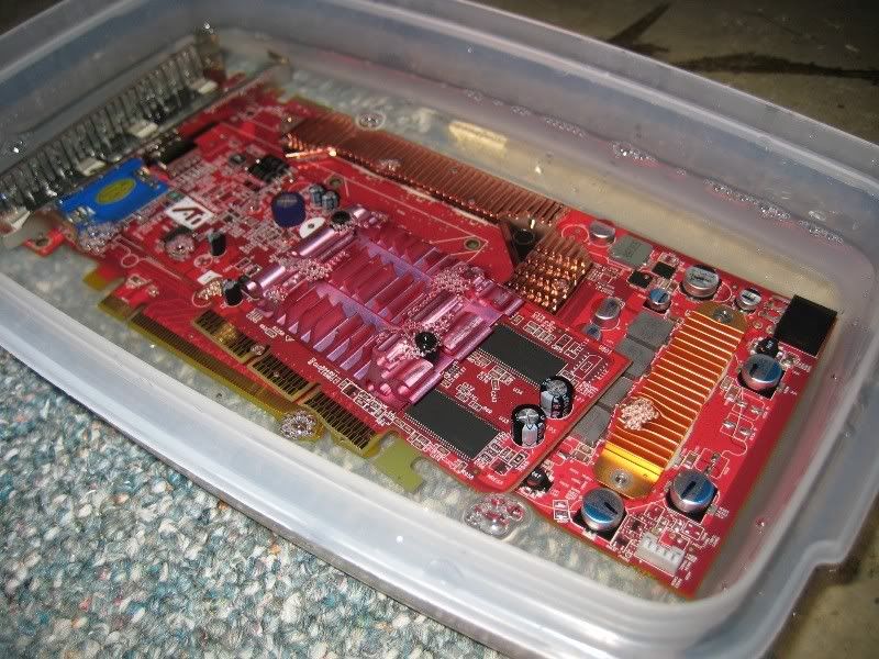
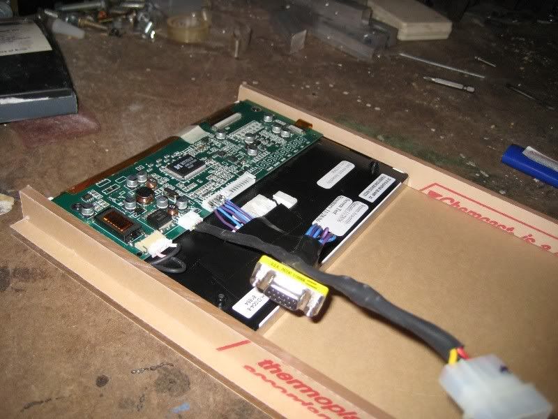
I decided I should probably test submerging some components in the oil. I'm mainly concerned with the oil eating away plastic, so I made sure to get 2 types of capacitors on my test subjects. My guinea pigs are a dead HD3870 and a 9200LE.
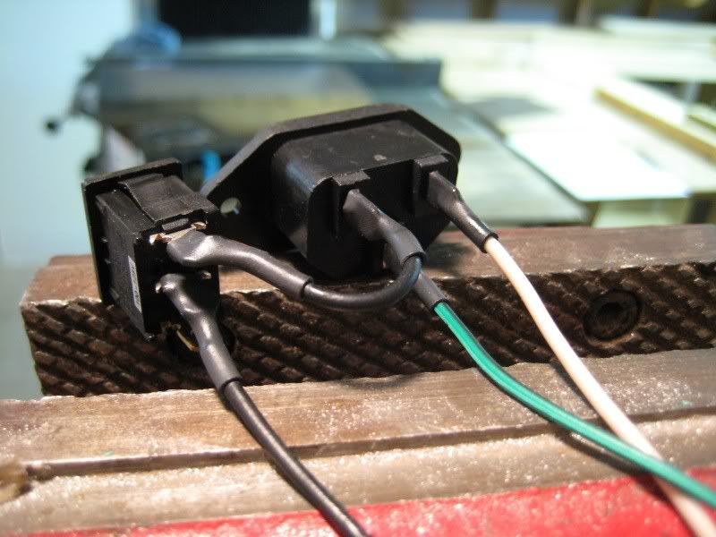
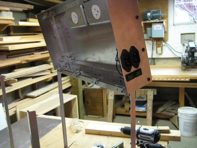
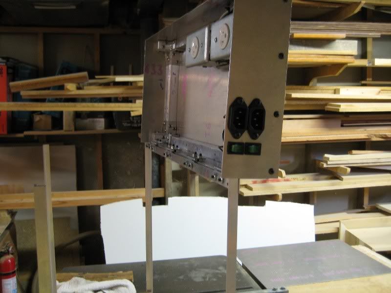
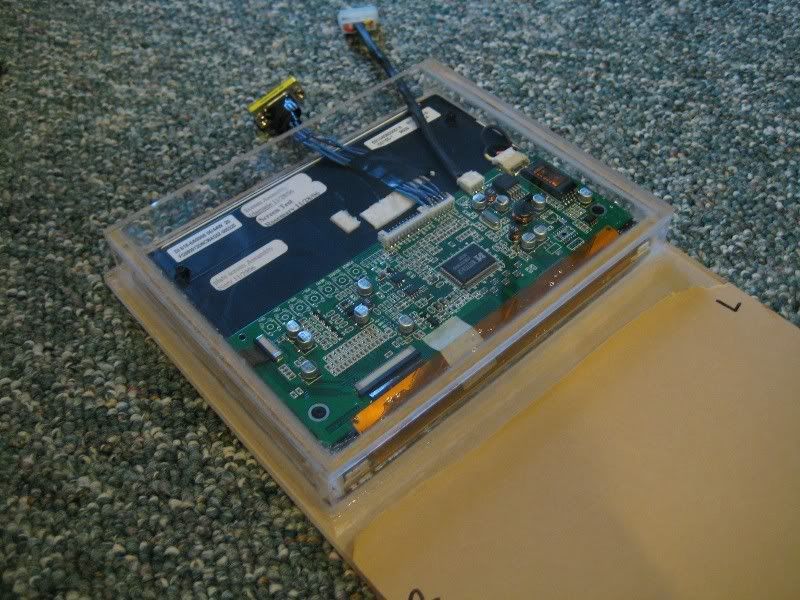
Then I got to some more serious work. Back shot of the wiring for the plugs and switches that the PSU and pump power cords will plug into.
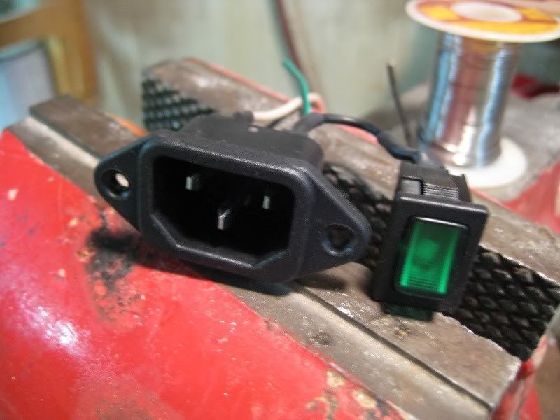
And from the front. I think there is an LED in the switch, but I don't know how to wire it up.
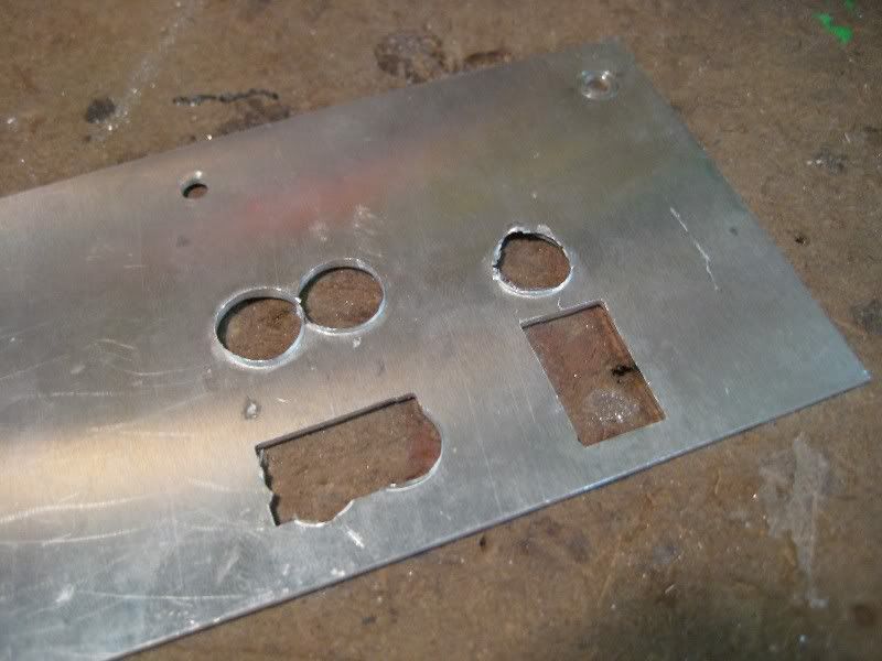
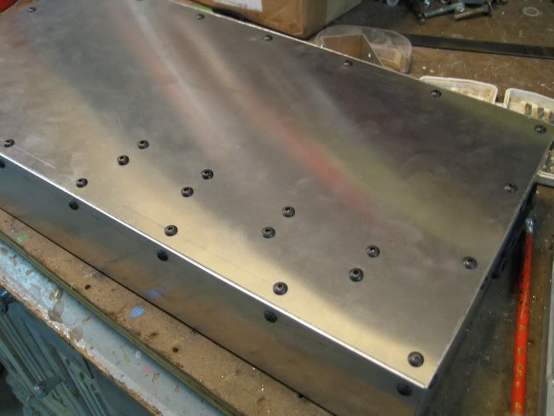
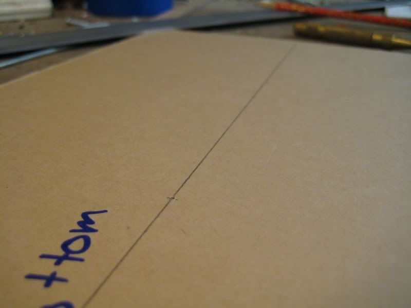
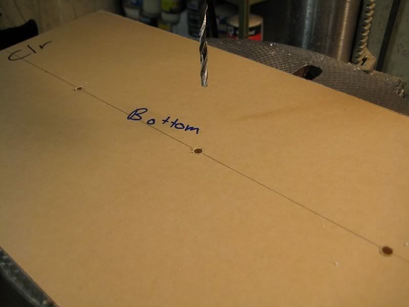
I made sure to draw the template for drilling the holes on the back this time.
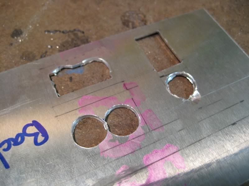
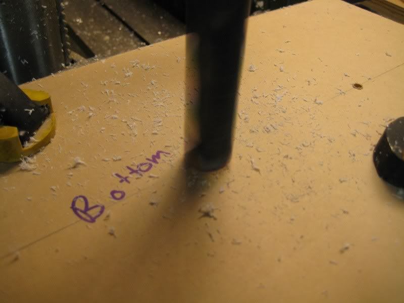
These actually aren't as much work to file as all of the buttons for the LCD were.
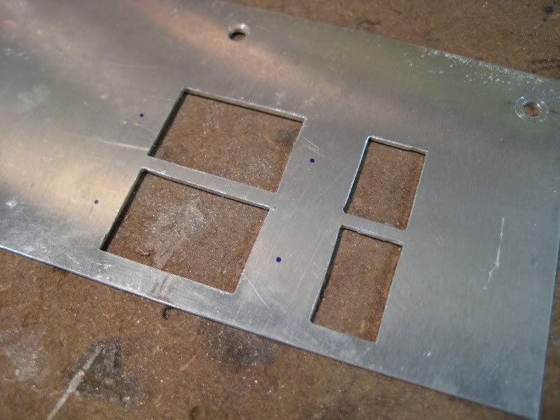
Still took a long time though.
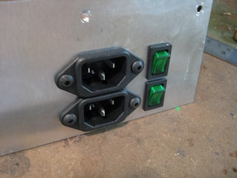
And then with the two sets mounted and in place.
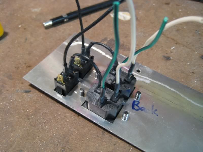
The wiring on the back.
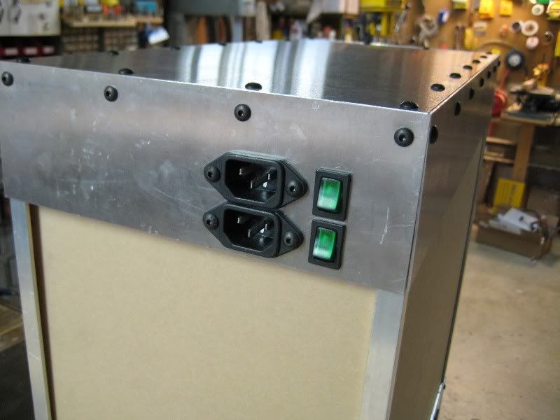
Quick test to make sure it fits on the frame.
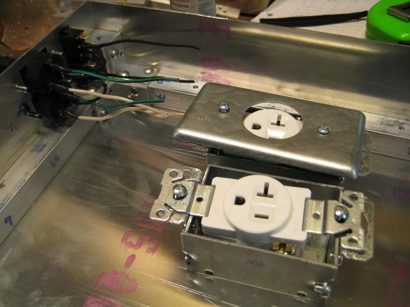
And now to wire up the internal outlets. I bought the conduit boxes, single outlet receptacles and the covers along with a few other goodies at Lowes today.
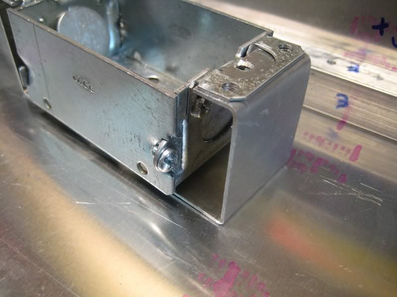
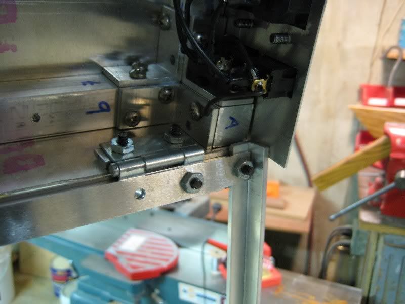
Then I bent a piece of aluminum for use as a mount.
And then did it again.
View from the top. 4 screws for each mount and a small 8-32 nut to hold it in place.
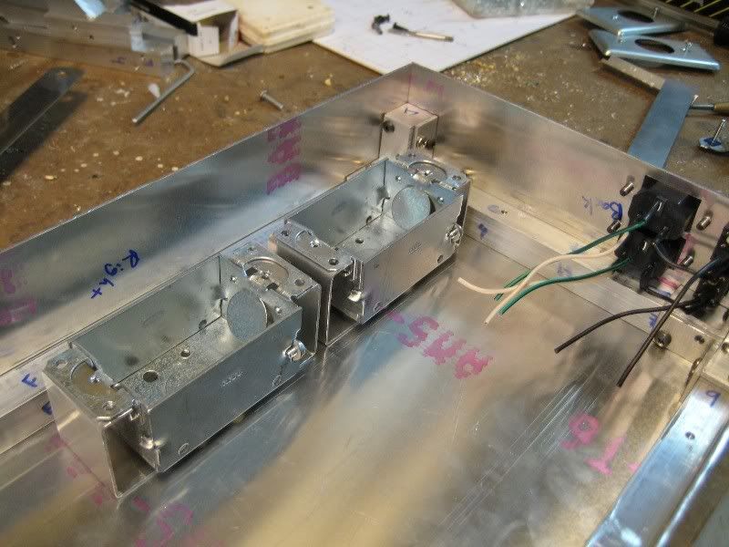
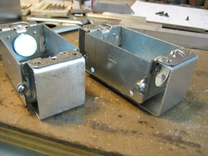
And what it looks like from the inside. I had to make sure to mount them out of the way so wires coming out of the motherboard wouldn't run into them. I almost mounted them in a position that would have made it impossible to plug stuff into the motherboard backpane.
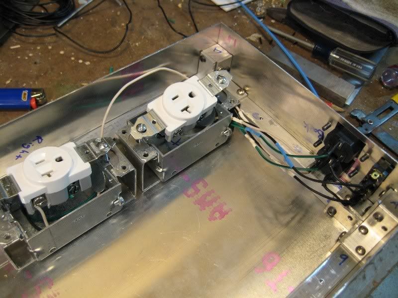
The outlets wired up.
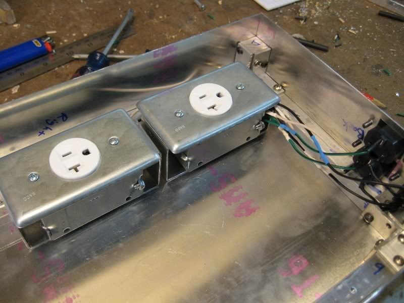
And all done.
That's where I stopped today. Since it was so nice, I went for a bike ride before dinner. Then after dinner I went and saw Watchmen, which was epic. Go watch it.
I decided I should probably test submerging some components in the oil. I'm mainly concerned with the oil eating away plastic, so I made sure to get 2 types of capacitors on my test subjects. My guinea pigs are a dead HD3870 and a 9200LE.
Then I got to some more serious work. Back shot of the wiring for the plugs and switches that the PSU and pump power cords will plug into.
And from the front. I think there is an LED in the switch, but I don't know how to wire it up.
I made sure to draw the template for drilling the holes on the back this time.
These actually aren't as much work to file as all of the buttons for the LCD were.
Still took a long time though.
And then with the two sets mounted and in place.
The wiring on the back.
Quick test to make sure it fits on the frame.
And now to wire up the internal outlets. I bought the conduit boxes, single outlet receptacles and the covers along with a few other goodies at Lowes today.
Then I bent a piece of aluminum for use as a mount.
And then did it again.
View from the top. 4 screws for each mount and a small 8-32 nut to hold it in place.
And what it looks like from the inside. I had to make sure to mount them out of the way so wires coming out of the motherboard wouldn't run into them. I almost mounted them in a position that would have made it impossible to plug stuff into the motherboard backpane.
The outlets wired up.
And all done.
That's where I stopped today. Since it was so nice, I went for a bike ride before dinner. Then after dinner I went and saw Watchmen, which was epic. Go watch it.
dr papadakalis
Weaksauce
- Joined
- Jan 2, 2009
- Messages
- 82
can't wait to see how this turns out!!
hell yeah, watchmen is epic!
hell yeah, watchmen is epic!
Great skills indeed! Looking better every time
Regarding the LED in the switches, if you use them at the rated voltage (~110/220V), the LED will go on when the switch is in an 'on' position. No additional wiring required.
Regarding the LED in the switches, if you use them at the rated voltage (~110/220V), the LED will go on when the switch is in an 'on' position. No additional wiring required.
legoman666
Gawd
- Joined
- Dec 21, 2003
- Messages
- 638
Great skills indeed! Looking better every time
Regarding the LED in the switches, if you use them at the rated voltage (~110/220V), the LED will go on when the switch is in an 'on' position. No additional wiring required.
Thanks. Re: the LED: That's what I thought. However, it doesn't light up when I switch it on. I plugged a lamp into my outlets to test; the lamp powers on but the LED in the switch stays dark. There's a third lead on the switches that I was unsure what to do with, maybe I need to do something with it?
Nice work sir !
You can bet I'll be watching this.
------
I realize you already have your oil , but you might check out this thread if you havnt already.There's a lot of good info on submersion cooling fluids.
Thanks! I gave that thread a read, some good info in it!
great job here man, can't wait to see it finished...
Thanks.
good lord this is an impressive case.. i wish i had these kind of fabrication skills
Thanks, it just takes patience (and tools). You can do anything as long as you're patient and take the time to do it right.
can't wait to see how this turns out!!
hell yeah, watchmen is epic!
Thanks! And I want to see it again...
Thanks. Re: the LED: That's what I thought. However, it doesn't light up when I switch it on. I plugged a lamp into my outlets to test; the lamp powers on but the LED in the switch stays dark. There's a third lead on the switches that I was unsure what to do with, maybe I need to do something with it?
That's different from the illuminated switches I have seen/used... do you have a data sheet of your switch, or at least a model number? It may be that your switch uses a different anode/cathode source or so. No idea really
Do you happen to know whether the switch is SPST or SPDT?legoman666
Gawd
- Joined
- Dec 21, 2003
- Messages
- 638
That's different from the illuminated switches I have seen/used... do you have a data sheet of your switch, or at least a model number? It may be that your switch uses a different anode/cathode source or so. No idea really
It is this switch: http://www.mouser.com/Search/ProductDetail.aspx?qs=sGAEpiMZZMtNT9UGfLL4eOd3cDQgL8vM5%2bq1URNopM4=
SPST. The "data sheet" just links to the manufacturer's site. It doesn't mention an LED. You think it would advertise it if it had one.
It is this switch: http://www.mouser.com/Search/ProductDetail.aspx?qs=sGAEpiMZZMtNT9UGfLL4eOd3cDQgL8vM5%2bq1URNopM4=
SPST. The "data sheet" just links to the manufacturer's site. It doesn't mention an LED. You think it would advertise it if it had one.
Under 'Materials':
ILLUMINATED ACTUATOR: Polycarbonate, matte finish.
So yes, it is illuminated, there is however no data sheet AFAICT which spells out the internal wiring, although the spec page lists:
Momentary and maintained functions
Which I have no idea what they mean exactly, other than that one side is perhaps a switch and the other side a button (NO/NC), which'd be a very, very unusual configuration...
legoman666
Gawd
- Joined
- Dec 21, 2003
- Messages
- 638
Under 'Materials':
So yes, it is illuminated, there is however no data sheet AFAICT which spells out the internal wiring, although the spec page lists:
Which I have no idea what they mean exactly, other than that one side is perhaps a switch and the other side a button (NO/NC), which'd be a very, very unusual configuration...
Hm, I missed that. Maybe I'll try hooking up 2.2v to the extra lead or something.
Edit: actually Googling the part number turned up this PDF: http://www.ck-components.com/index....ref=15104&lang=en&width=&height=&format=&alt= I might need to do some quick re-soldering to get the LED to illuminate.
fluke420
Gawd
- Joined
- Jul 9, 2003
- Messages
- 927
Nah, you don't have a LED version, but apparently a neon bulb one (125VAC). Apparently all you need to do is to hook terminal 3 up to ground.
That is correct. You need to establish another ground for the light to work.
legoman666
Gawd
- Joined
- Dec 21, 2003
- Messages
- 638
That is correct. You need to establish another ground for the light to work.
Ah, thanks guys. Yes I see it on the spec sheet now; I didn't look closely at it earlier. I'll give it a shot!
horrorshow
Lakewood Original
- Joined
- Dec 14, 2007
- Messages
- 9,440
I tip my hat to you sir.
Excellent work!
Can't wait to see it finished....
Excellent work!
Can't wait to see it finished....
legoman666
Gawd
- Joined
- Dec 21, 2003
- Messages
- 638

Busy busy busy.... Oh so tasty...
Reality
[H]ard|Gawd
- Joined
- Feb 16, 2003
- Messages
- 1,937
Reece's cup cheesecake? I want :|
legoman666
Gawd
- Joined
- Dec 21, 2003
- Messages
- 638
holy crap
-(Xyphox)-
Supreme [H]ardness
- Joined
- Sep 9, 2004
- Messages
- 6,518
that cake looks awesome... great work so far
legoman666
Gawd
- Joined
- Dec 21, 2003
- Messages
- 638
Thanks guys! It tastes as good as it looks too!
Lol, better get here fast, it's going quickly.
Mind if I hop over for a bite of that cake?
Lol, better get here fast, it's going quickly.
legoman666
Gawd
- Joined
- Dec 21, 2003
- Messages
- 638
This is a combination of work from Sunday up to today (Thursday).
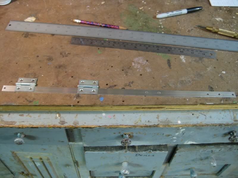
I bought 4 small hinges that will be used to allow access to the top compartment. I cut a small strip of aluminum and drilled the holes for all 4 hinges.
I cut about 3/4" off the bottom of the right side sheet and then cut a piece to replace it. I drilled the holes through it for the hinges.
Each hinge is held in place with 2 small 8-32 nuts.
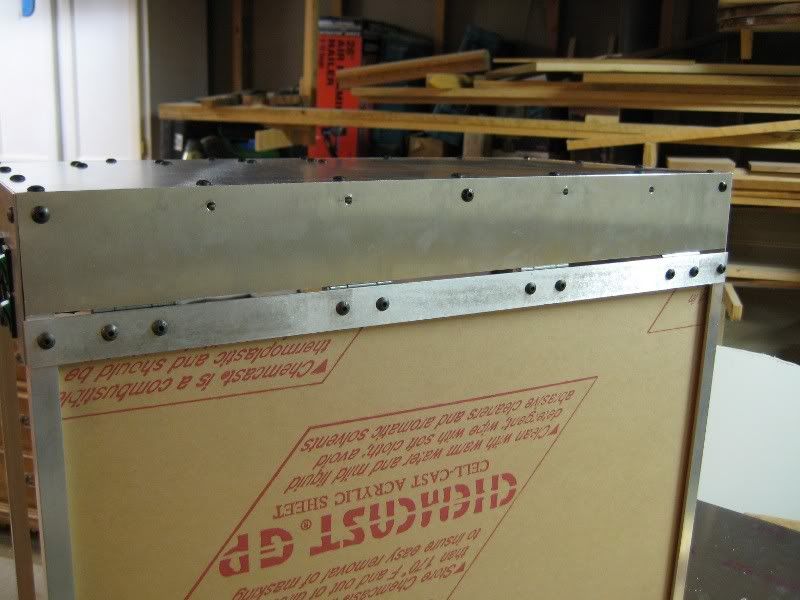
And then I did the same for the top. You will notice, on the top section I had to put small 1/8" spacers in between the hinges and the panel. This is to make both sections of panel even as the lower section is bumped out by the 1/8" angle risers.
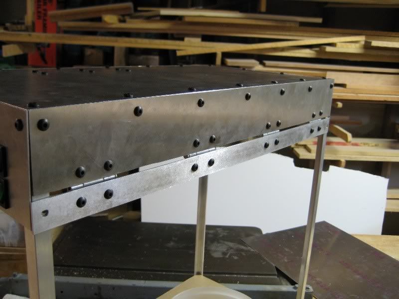
View from the outside.
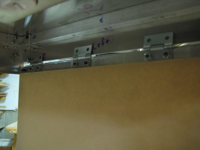
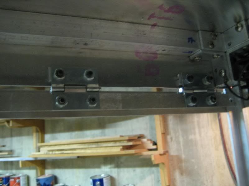
And the hinges in action. I still need to do a little more filing so I can open it at least 90 degrees. If it can't open far enough, I won't be able to pull the motherboard tray out of the oil. Speaking of which...
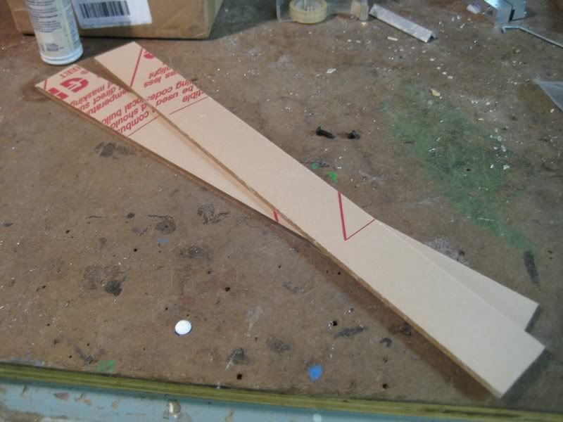
I cut 2 strips of 1/4" acrylic that will be have the drawer sliders attached to them. Although not shown in this picture, these were cut to the proper length, about 12".
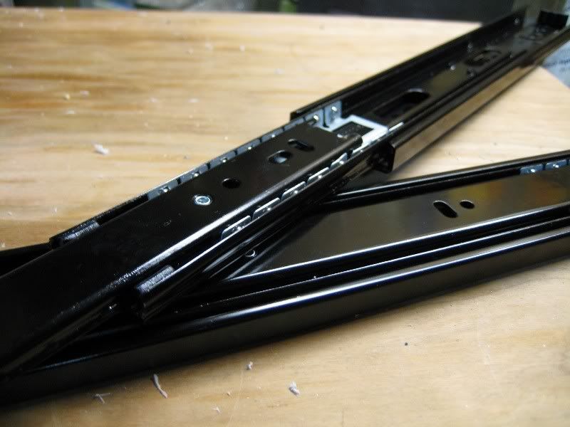
Here are the drawer sliders I'm going to use. I washed them with dishsoap several times to remove all of the oil and grease on the ball bearings. These will be submerged in mineral oil and as such, do not require extra lubrication. Besides, I don't want the two oils mixing.
After a discussion with Elledan on [H], we figured out what I needed to do to get the neon bulbs in the switches to light up. The third pin on each switch had to be grounded. So I soldered a short connection between the two ground pins on both switches and then grounded them both by wiring them to the case (which is grounded). It is a bit dark, but you can just make out the ground going to the screw in this pic.
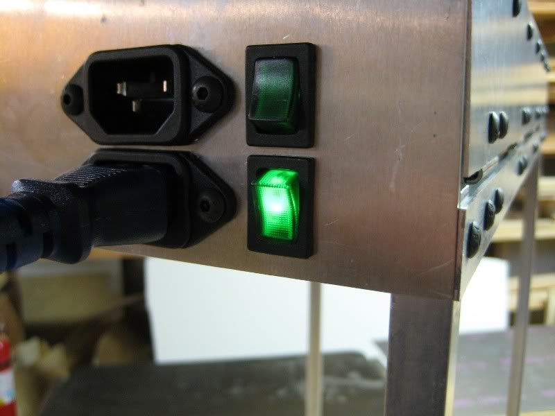
And then here it is in action. Looks good.
Comments?
I bought 4 small hinges that will be used to allow access to the top compartment. I cut a small strip of aluminum and drilled the holes for all 4 hinges.
I cut about 3/4" off the bottom of the right side sheet and then cut a piece to replace it. I drilled the holes through it for the hinges.
Each hinge is held in place with 2 small 8-32 nuts.
And then I did the same for the top. You will notice, on the top section I had to put small 1/8" spacers in between the hinges and the panel. This is to make both sections of panel even as the lower section is bumped out by the 1/8" angle risers.
View from the outside.
And the hinges in action. I still need to do a little more filing so I can open it at least 90 degrees. If it can't open far enough, I won't be able to pull the motherboard tray out of the oil. Speaking of which...
I cut 2 strips of 1/4" acrylic that will be have the drawer sliders attached to them. Although not shown in this picture, these were cut to the proper length, about 12".
Here are the drawer sliders I'm going to use. I washed them with dishsoap several times to remove all of the oil and grease on the ball bearings. These will be submerged in mineral oil and as such, do not require extra lubrication. Besides, I don't want the two oils mixing.
After a discussion with Elledan on [H], we figured out what I needed to do to get the neon bulbs in the switches to light up. The third pin on each switch had to be grounded. So I soldered a short connection between the two ground pins on both switches and then grounded them both by wiring them to the case (which is grounded). It is a bit dark, but you can just make out the ground going to the screw in this pic.
And then here it is in action. Looks good.
Comments?
voklskier4452
2[H]4U
- Joined
- Nov 20, 2008
- Messages
- 2,111
this thing is looking better and better every day.. and the ball bearings are definitely a good idea, i love them on my ATCS 840
legoman666
Gawd
- Joined
- Dec 21, 2003
- Messages
- 638
You didn't credit me for solving the illumination issue
It's okay
Sorry! I copied and pasted the update from Bit-tech without making any changes. I normally go back through each post when I submit it to [H] to make sure it makes sense, answer any questions, and respond to comments. I posted this update late last night, so I didn't get a chance to do so. Thanks for helping to figure it out!
I tip my hat to you sir.
Excellent work!
Can't wait to see it finished....
Thanks!
This Looks amazing!
The cheesecake or the case?
this thing is looking better and better every day.. and the ball bearings are definitely a good idea, i love them on my ATCS 840
Thank you.
Sorry! I copied and pasted the update from Bit-tech without making any changes. I normally go back through each post when I submit it to [H] to make sure it makes sense, answer any questions, and respond to comments. I posted this update late last night, so I didn't get a chance to do so. Thanks for helping to figure it out!
I'll have some of that cheesecake as an apology
legoman666
Gawd
- Joined
- Dec 21, 2003
- Messages
- 638
I'll have some of that cheesecake as an apology
Ahahah, it's long gone
Wow that is crazy!!! Looking foward to the completion!!!
Thanks! Here's an update for you!
I did some filing and am now able to open the top more than 90 degrees.
Cutting the pieces for the "tank" that holds the 8" LCD on the front acrylic panel.
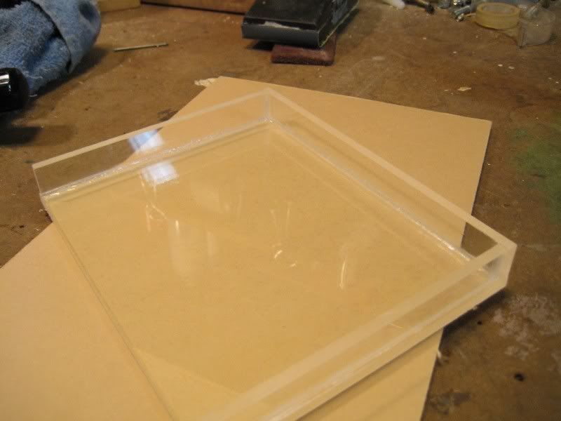
Then I glued it together with Weld-On and sealed the corners with silicone.
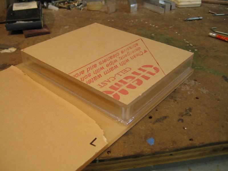
Then I glued the "tank" to the acrylic sheet. Weld-On is awesome. You just stick the two pieces together and apply the stuff to the joint. You can't apply it to the edges and then connect the two pieces since it evaporates so fast. Plus it dries in about 10 minutes and is strong enough to handle. Nearly full strength occurs after about 24 hours.
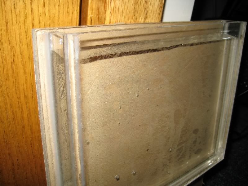
Making sure the tank is watertight so oil doesn't leak in.
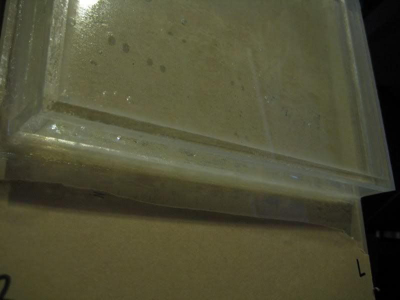
I don't see any drips!
So I emptied the water and made sure the LCD fit (lol, maybe I should have done that before I glued it all together :worried: )
I want to glue the tank together tomorrow, so I need to get the bottom of the tank ready. With that in mind, I marked the 3 locations for the bulkhead fittings. 1 for the radiator inlet, 1 for the outlet, and 1 for the drain.
First I drilled a pilot hole since my 7/8" drill bit does not like starting holes and I really don't want to ruin this sheet of acrylic.
Then drilling the big hole for the fitting. Sure takes a long time.
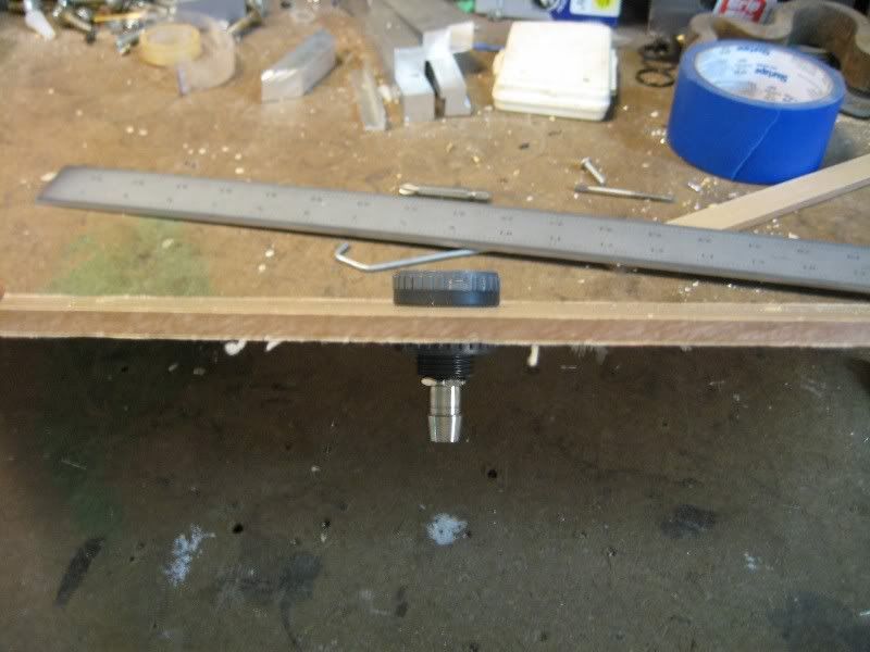
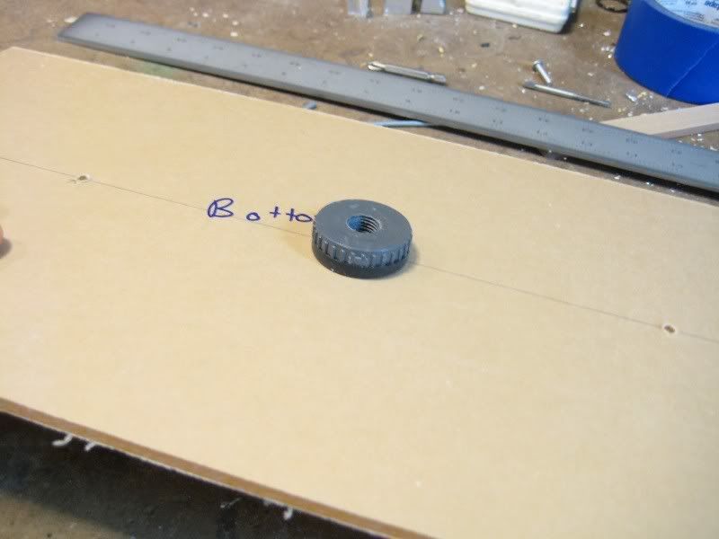
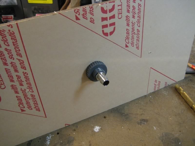
Here's how the bulkhead fittings work. The top doesn't come tapped, but that's easily fixed.
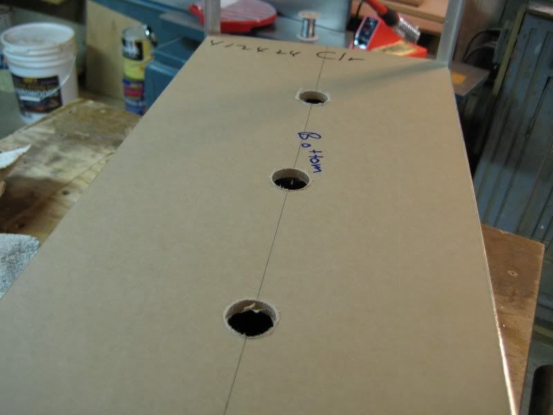
And all 3 holes done.
That's where I stopped today. Tomorrow I want to glue the entire tank together. I think I'm ready to do it; I'm fairly certain I have everything prepared. Comments?