Taking another shot at HD44780

awdark

[H]ard|Gawd
Joined
Mar 22, 2003
Messages
1,630
Okay I am taking another shot at getting my HD44780 lcds to work.

Question 1:
Are they supposed to show anything when you just power them up. As in not connected to parallel, just power to the chip.

Question 2:
How should the Parallel Port be setup? I have installed port95nt and in the bios, the Parallel port is using 378 and in SPP mode.

Thank you.
 
Okay, one thing I do know is that if I base it on the Hitachi data sheet, my wiring to the parallel port is perfect. Pin 6 goes to the correct pin on the chip itself etc.

Can someone please make me a dummy's diagram for POWER? I dont understand schematics very well and I tried to put a bunch of diodes the way I thought would be correct and melted a wire.

I thought it was
1- gnd
2- +5
3- gnd
but that obviously doesnt work.
 
awdark said:
Okay, one thing I do know is that if I base it on the Hitachi data sheet, my wiring to the parallel port is perfect. Pin 6 goes to the correct pin on the chip itself etc.

Can someone please make me a dummy's diagram for POWER? I dont understand schematics very well and I tried to put a bunch of diodes the way I thought would be correct and melted a wire.

I thought it was
1- gnd
2- +5
3- gnd
but that obviously doesnt work.
If you melted a wire, the display is prolly shot now! Ouch... I don't have any experience with that display. But circuit diagrams work for me, scan it in and send it my way [email protected]
 
Yeah, I found something similar to that... I know my parallel wires should be correct. The problem is the power cables. I assume that is why I never see the black line/white line at bootup. I figure that I should at least see that (once I see that its a software issue).

:p Ima little dense when it comes to schematics... particularily that variable resistor thing there. I want to avoid the variable and go for a fixed resistor instead.
 
pin 3 i believe is used for contrast, if you have it grounded thats probably why you aren't seeing anything though. This is just off the top of my head though and I haven't dealt with these in about 4 years.
 
Yes Pin3 is for contrast. I used diodes because the only diagram I foudn that seemed logical in setting up the power had 2 diodes in it... so I went eh why not and just added them :p
Still no picture tho. Should I tie contrast to +5v power then?
 
awdark said:
Hey again. Well I'll give it a shot, even tho I'm no electronics wizard....
The variable resistor "thigy" is a pot- (potentiometer) like a volume control or fan speed control. I wouldn't directly connect power to the contrast pin, but instead use a resistor there if you don't want adjustability. The best way is to get the 10k ohm potentiometer, set up the display, adjust the pot to the level you want the screen contrast to live at, and then measure the resistance with a multimeter across the pot connections to find out the resistance you need for a fixed resistor. You could always return the pot later too :)
Looks like pin 15 and pin 2 share a connection to 5 vdc. Supply both these leads at the same time with your 5 volts. Looks like pin 1 will be grounded as well as half the dam parallel port... Make sure you supply an external ground to all these pins like it shows, don't rely on the ground provided by the port. Pin 16 is prolly for brightness and varies the backlight's connection to ground from the looks of it... Good luck! :eek:
 
Oh, so it looks like +5 goes to the contrast with through a resistor and connects directly to pin 2... Ignore that part where the other half of the pot looks like its grounded?
Yeah pin 15 and 16 are tied directly to the backlight (I know because thats where the traces lead to :p )


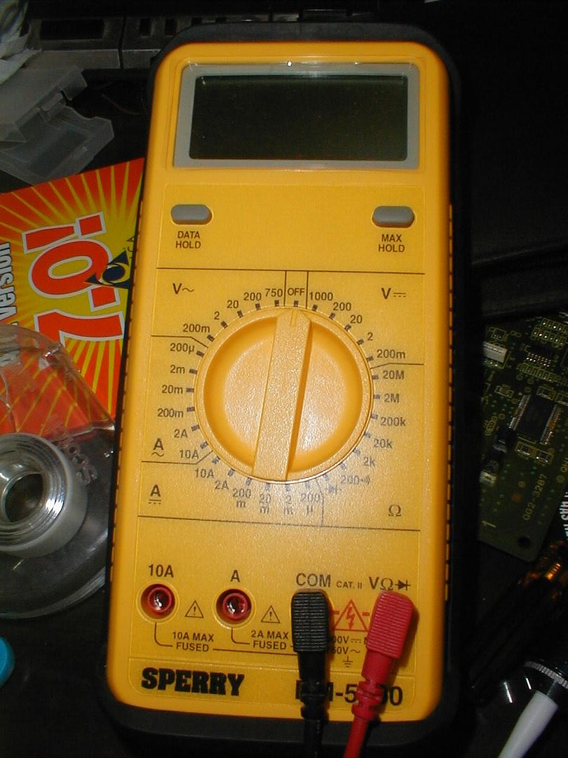
Perhaps I should make a different thread for this but this is my multimeter:
P1010003.jpg


When it is referenced to "10k ohm resistor" where would I set it so I can find 10k ohms? I understand the voltage part but never figured out the amperage/resistance part.
 
Okay, putting a variable resistor bridging Pin2 with Pin3 was unsucessful. Perhaps I have fried the board completely. (Is there any diagnostics I can do??)

Thanks
 
get rid of the diodes on the power. Its possible, but unlikely, that they are either the wrong way, or its possible they are causing enough of a voltage drop to cause the controller to not have enough juice (doubtful but you never know)
 
Yeah I took those out after I melted a wire.

Now its just

5volt to pin 2 and variabled to pin 3
gnd to pin 1
Parallel port connected to computer
Hit power button

nothing on the screen still :(


http://www.overclockers.com.au/~mwp/cc/guides/setup-hd44780.htm
Perhaps enlightment perhaps doom. Not sure.

EDIT:
Things I CAN confirm.
Parallel is going to the controller chip (Multimeter parallel port to leg on IC)
Power getting to the LCD (paralleled the power to the LED backlight with a resistor backlight ON)
Parallel Port in EPP mode from my reading it sounds like these screens like EPP in bios.
Contrast adjust. I have wired a POT exactly like the guy described in the link above and get nothing. Im not sure if my POT's resistance is what I actually want... might be way to high but I think it should be OK.
Number of screens "Dead" can confirm 2 due to experimental polarity switch and very hot IC.
Two screens left, one I tweaked with the other should be new.

Goal is to get Black line White line for "ready to recieve"

Still want to know from anyone with a HD44780 LCD what it shows if anything when you only give it power and no parallel.
Also want to know if there is things I can test to make sure the chip is alive? Like some test pin with some sort of resulting resistance to X and Y will prove something is alive or something.

Thanky ou.
 
awdark said:
When it is referenced to "10k ohm resistor" where would I set it so I can find 10k ohms? I understand the voltage part but never figured out the amperage/resistance part.
Set your multi to 20k under the ohm settings on the right side of the control knob.
 
Are you using a cut parallel cable (ie cut up printer cable), I tried that and it absolutely sucked, I nuked an LCD myself, what I used was a ribbon cable, it is a lot easier to figure out the pinouts for where each cable goes.

Sorry to hear that you're not getting them wired up...

I finally gave up on the LCD's and went for a VFD, it was way easier in the end.

I set mine up the same way as these guys.

http://www.icehw.net/article.php?id=99

Good Luck

MD
 
Yes, cut parallel cable.
I confirm the wiring with multimeter and its not too hard to wire because its like white, white with line, orange, orange with line, etc
 
its more then likely the contrast adjustment. set your multimeter to volts and test between the pot's wiper output (middle lead) and ground. make sure the voltage is changing.
and measure from each power point to ground.
 
Both points say 5.02 volts. Resistance between 1 and 2 on the lcd is about 4.86 ohms (probably have the decimal off a few units...)
 
Taken from http://www.overclockers.com.au/techstuff/a_diy_lcd/

Code:
Pin.Connect to...................................Function
1...Earth (Black wire on Molex connector)....... Earth 
2...5V (Red wire on Molex connector)............ Power 
3...Earth (Black wire on Molex connector) .......This adjusts the contrast of the LCD 
.................................................digits. Earthing pin 3 provides 
.................................................maximum contrast. A 10k pot can be
.................................................used to provide a variable value if required. 
4...Parallel Port pin 16 (Green/white wire) .....Register Select 
5...Earth (Black wire on Molex connector)........Read/Write. Since we are not going to read 
.................................................data from the LCD, we can ground pin 5; 
.................................................to set it permanently in write mode. 
6...Parallel Port pin 1 (Pink wire)..............Enable - Strobe 
7...Parallel Port pin 2 (Red wire)...............Data bit 0 
14..Parallel Port pin 9 (Grey wire)..............Data bit 7

When the LCD is first powered up the top line of characters should come on faintly untill the clear command is given. Connecting the contrast pin directly to 5V or ground will give full and minimum contrast. Can't remember which way round sorry.

If the chips get hot at all you have connected the power the wrong way round and the lcd is probably dead or damaged.
 
is there more then 14 pins?

it might have backlit and/or contrast (or whatever it's called) pins... so without a little bit of power going into them, it'll look like it's off when it's on.
 
:( I see.
So it looks like they are powered correctly. (I have them all wired to the backlight so backlight = power to whole unit)
I guess this means I have fried them all somehow... Oh well... I did get them at a good deal. Perhaps I overheated, ESD, or just cooked the data lines.

I guess time to hunt for a VFD so my HTPC will have the look I seek ;)
 
Which one did you cook, I can't remember if it was the small, medium or large ones you bought...I'm all out of VFD's too...but I can have a look around for you.

MD
 
Oh... I bought 4 of the 2x16 lcds.
Im pretty positive 2 of the 4 16x2 lcds were fried from improper wiring (I wire them correctly and it doesnt work so I go WTF and wire it the other way and thats typically not a good idea) the other two I tried to power the way I thought was logical for max contrast (pin 1 gnd pin 2 +5 pin 3 gnd) but nothing pops up either. So I think I probably screwed the other two up during my path of testing what works and doesnt work.

I guess im back to using my Palm M100 with Palmorb as my LCD :)
 
send me a PM, I'll see what I can scrounge up...may not find anything any time soon...my wife is in labor as I type...LOL

Later

MD
 
Hmm hardforums was broken for a while for me...
Its okay, I might go for a PSone LcD :p

:eek: Your wife was in labor and you were still online?! congratulations tho :)
 
Yeah she's pretty tough...she labored at home for most of the time with both our children, first one was 32 hours, 22 without medication...

I don't mess with her..LOL

Later

MD
 
Back
Top