Hello everyone!
As I'm coming to the end of my career as a full time master's student in the next 4 months, I decided to build an HTPC for the non-existent HDTV that I own . The plan is to have it finished around the time I graduate (March), or sooner. As I'm sure everyone here knows, it's hard to keep a consistent log as a student, let alone finish a build, but I'll do my best.
Specifications:
Currently Bought:
Motherboard: Zotac Geforce 9300-ITX WiFi
Processor: Intel C2D E7400 2.8GHz
Memory: 2GB Kingston DDR2 800
Hard Drive: Western Digital Scorpio Blue 2.5" 80GB
Operating System: Ubuntu 9.10 with XBMC
Future Purchases: (Too poor right now!)
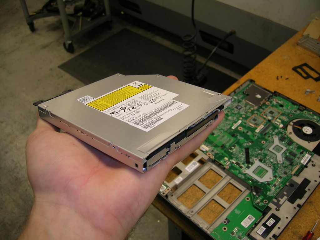
Optical Drive: Slimline Blu-ray Player
CPU Heat Sink: Undecided...It's between the Thermolab Nano, Silverstone NT07, and Zalman VF2000 (due to height restrictions of <45mm).
Purpose:
Since everyone has a different purpose for their HTPC, I figure I'll state mine up front. It won't be storing any media locally, as I have a NAS set up with the goods already. I want an attractive, convienent front end to show my media, stream 1080 content, and the option to occasionally play a Blu-ray right from the computer itself.
I looked up several pre-boxed HTPC's, but none really caught my eye. After this failed reconnaissance mission, I decided to design my own.
Design:
I really have no idea what influenced me on this project. It had to be small. Barely big enough to fit the mini-itx board. It also had to fit all of the components snugly. It also had to look sexy enough for my taste.
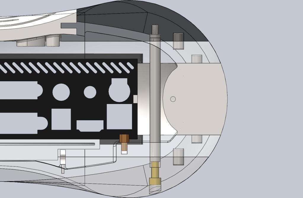
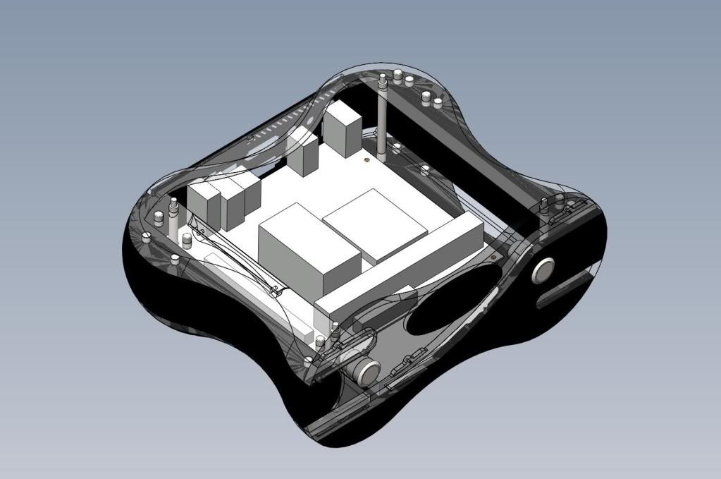
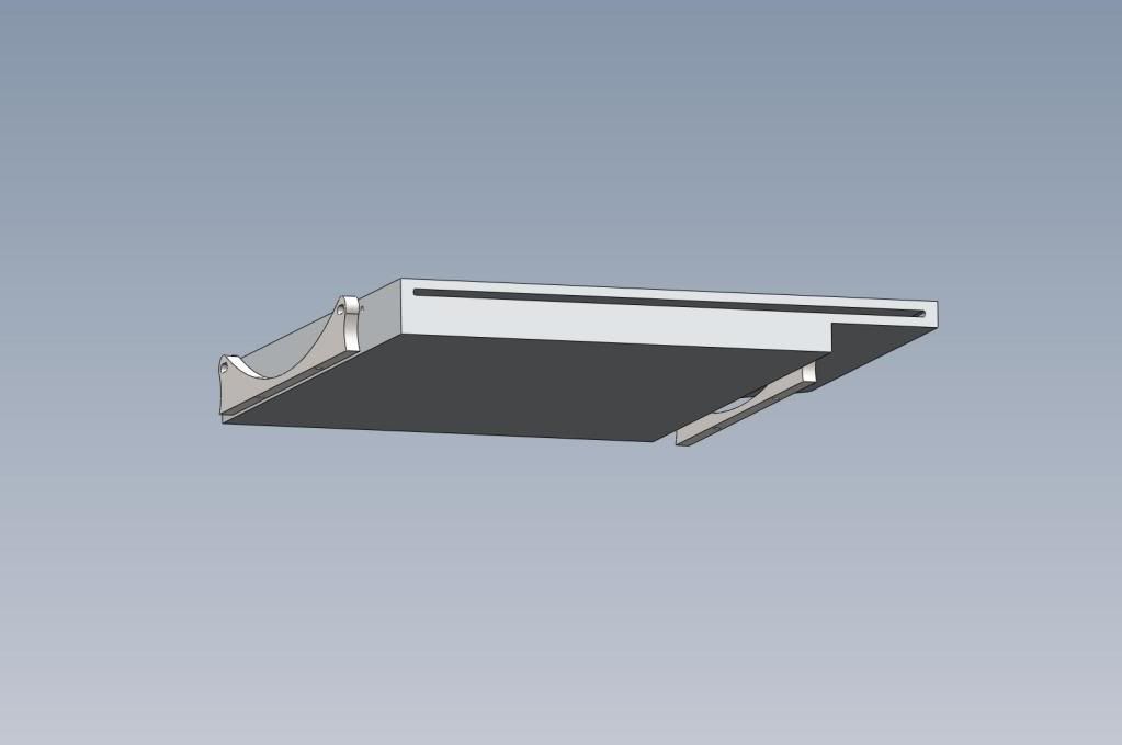
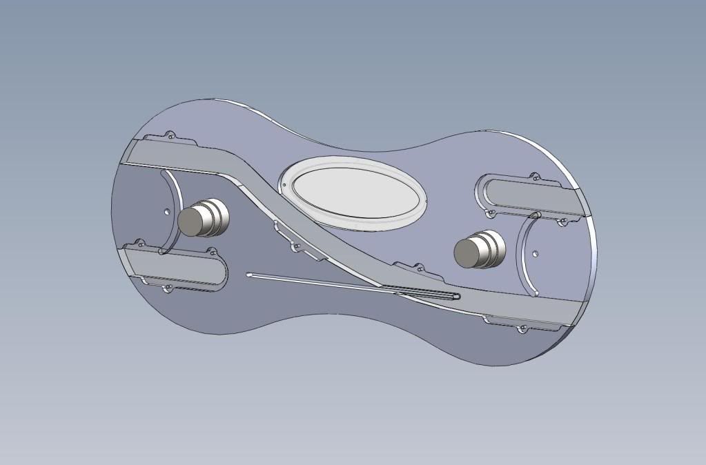
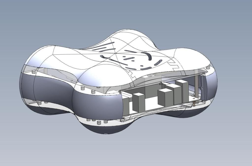
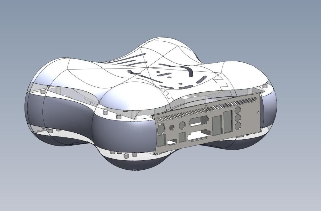
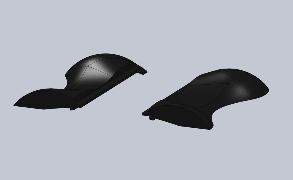
Without further ado, here are some drawings. Solidworks was my program of choice, since I've been using it for 5 or so years.
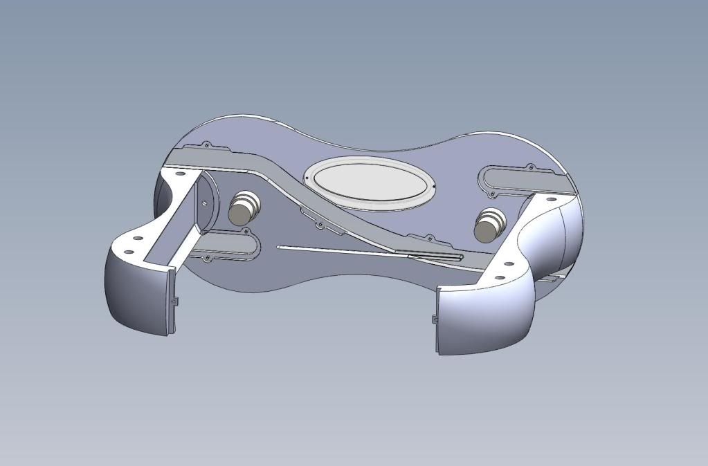
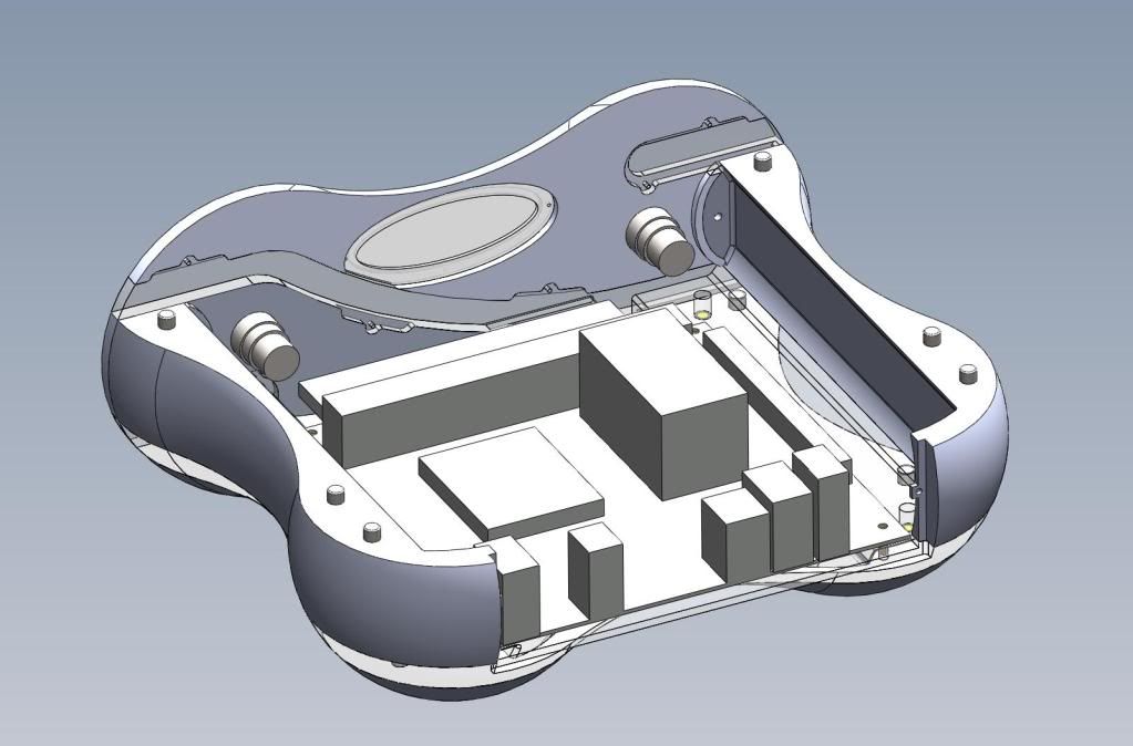
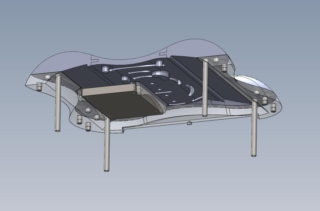
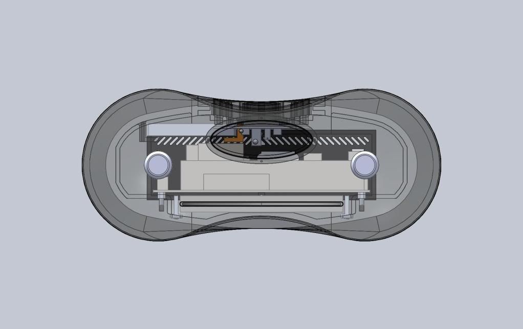
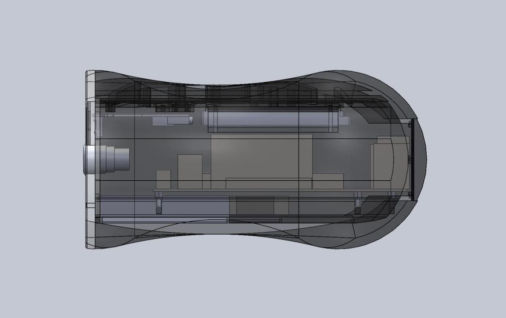
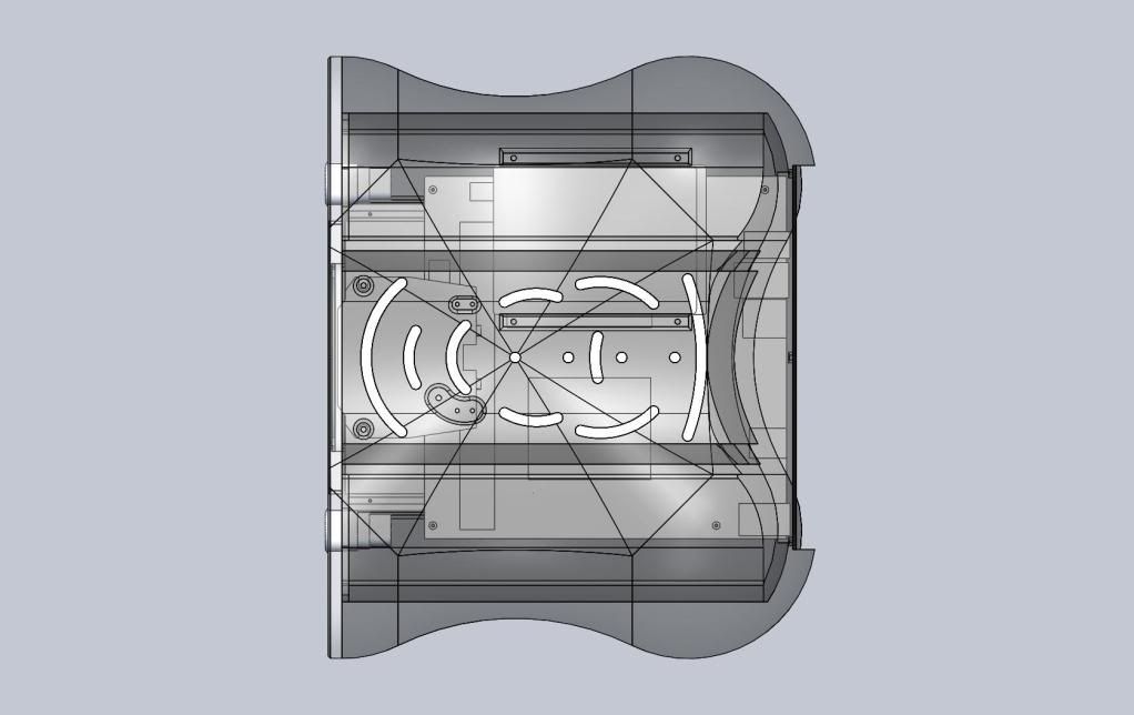
You can see in these drawings I measured everything out and modeled the components so everything can fit nicely. If anyone has any questions as to the logistics of how the case will go together, ask me, and I may have an answer (or I may not know yet :duh.
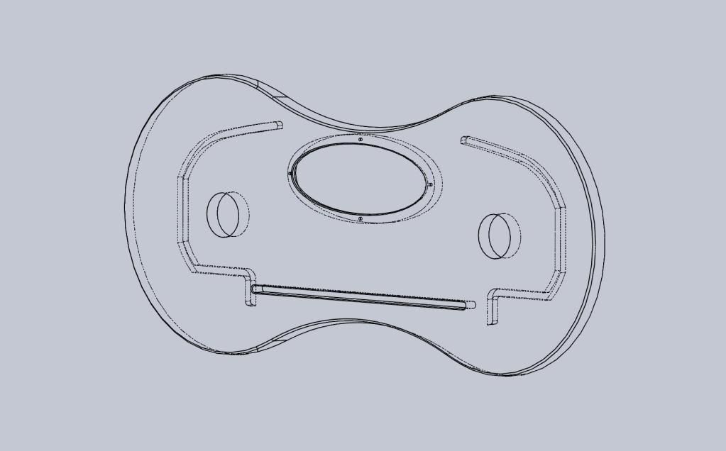
Quick rendering in Solidworks

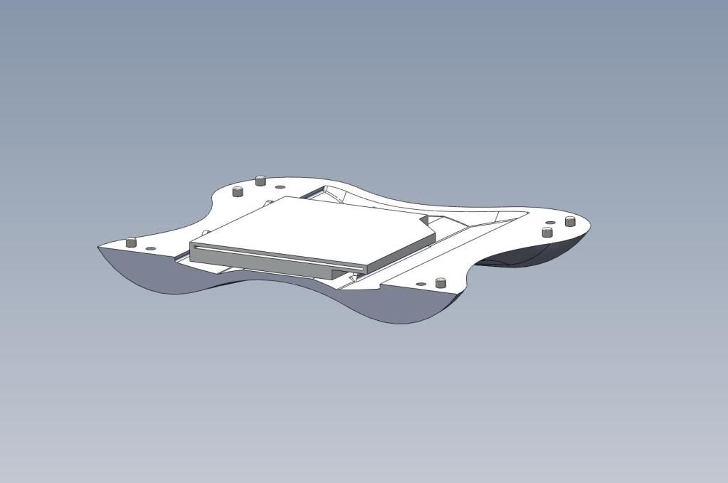
Wireframe View - Front
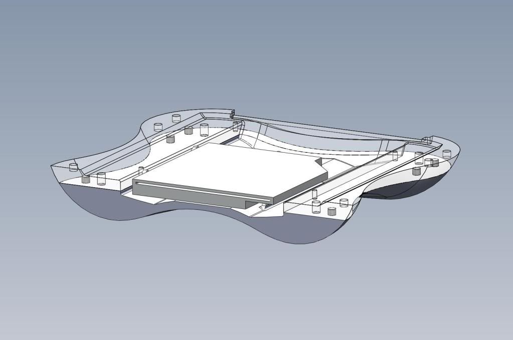
Wireframe View - Side
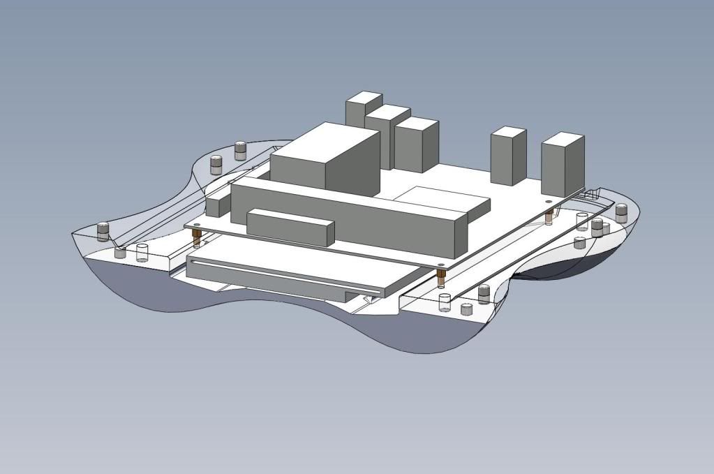
Wireframe View - Top
Machining:
For the past year or so, I've been working in the machine shop on campus here. I've had machining experience before this, but working here has given me the chance to improve on this. We have a HAAS 3-axis vertical mill, which I adorewaah: no 4-axis). Most of the work will be done on the CNC due to the complex shape that the case takes, since I like things to be oh-so-easy.
Also, a note. This won't and can't (with my budget and limited machines) be machined from a solid piece of material. The plan is to divide the case into sections and machine them individually, then connect them together to make the full case. Think of one of those foam Millennium Falcon jigsaw puzzles, only this time it's aluminum :clap:. I plan on machining all of the insides first, lining everything up, then machining the outside all at once.
Frontplate:
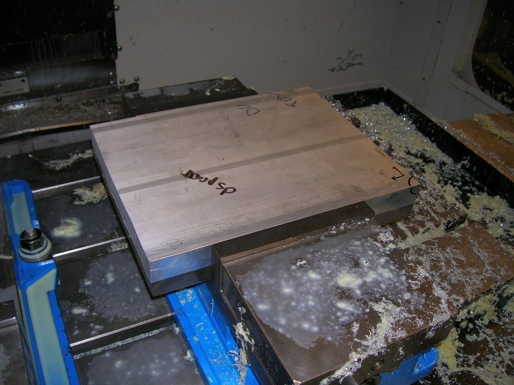
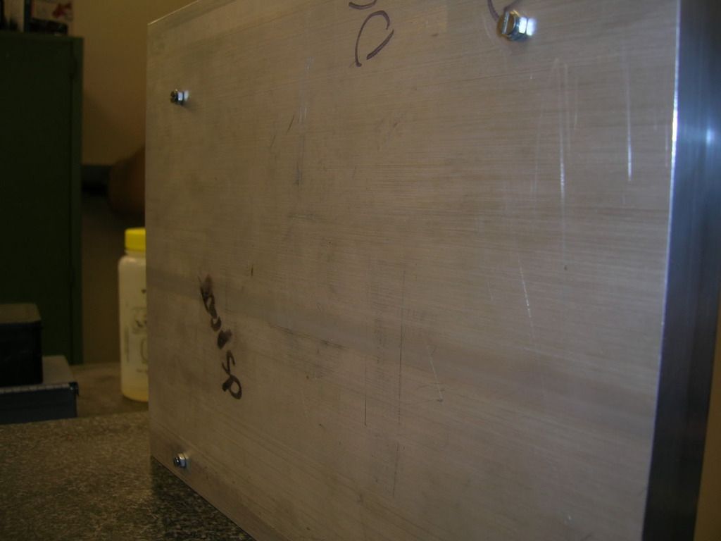
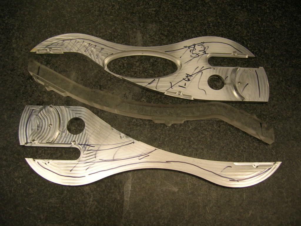
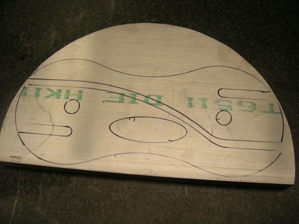
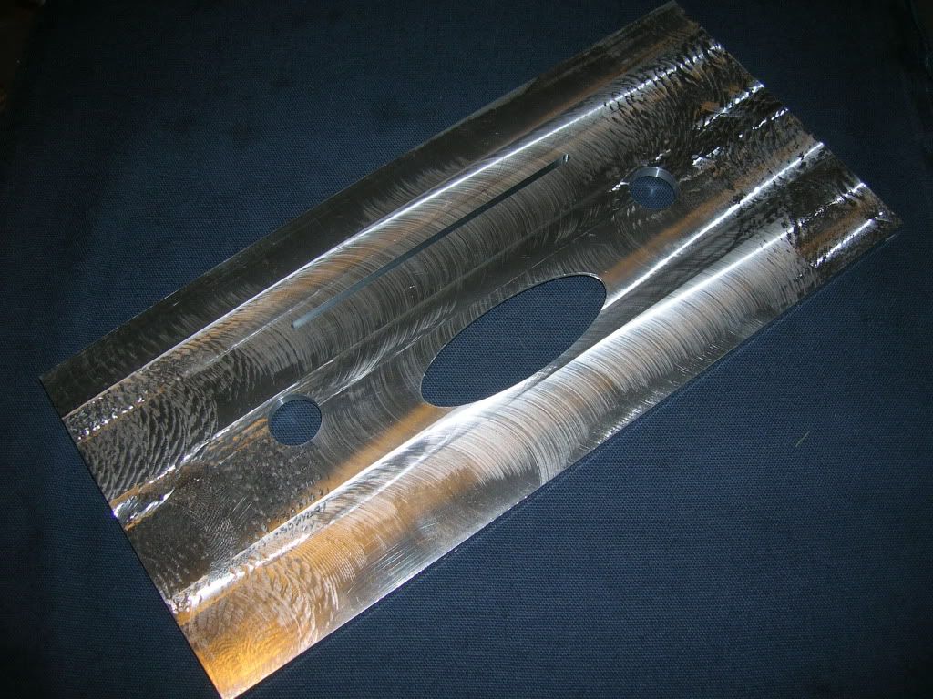
The frontplate was the easiest starting point of this whole project. Flat, thin, and not much to it (if I had a nickel...). Unfortunately, I won't have any process pictures for a few sections, since I'm an idiot and kept forgetting the camera. It's simple, however. Take a slab of 3/8" aluminum, cut to size, face with a sick nasty multi-head cutter, take drawing, import to Mastercam, voila!
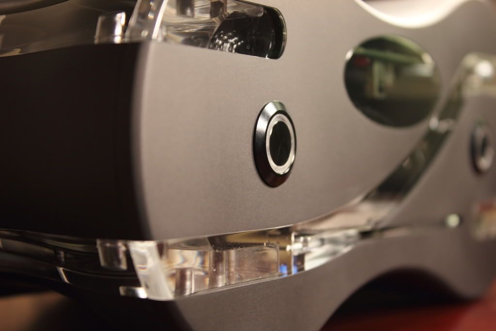
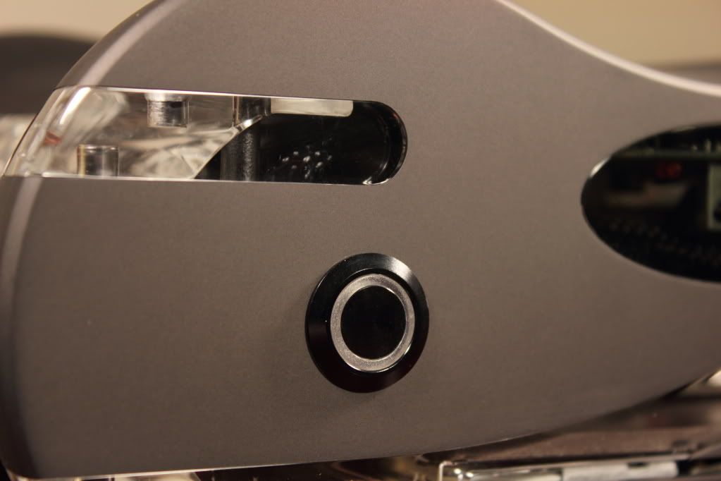
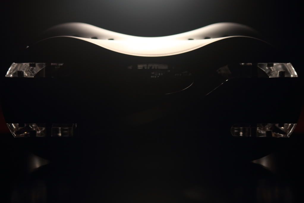
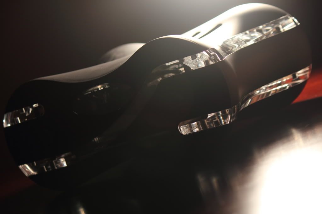
Here's a snap of the half-completed frontplate. Again, I'm saving the contour for the very last. Mmm shiny.
Wireframe:
Front:
Back:
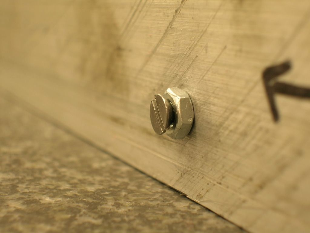
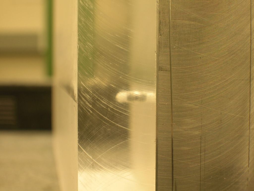
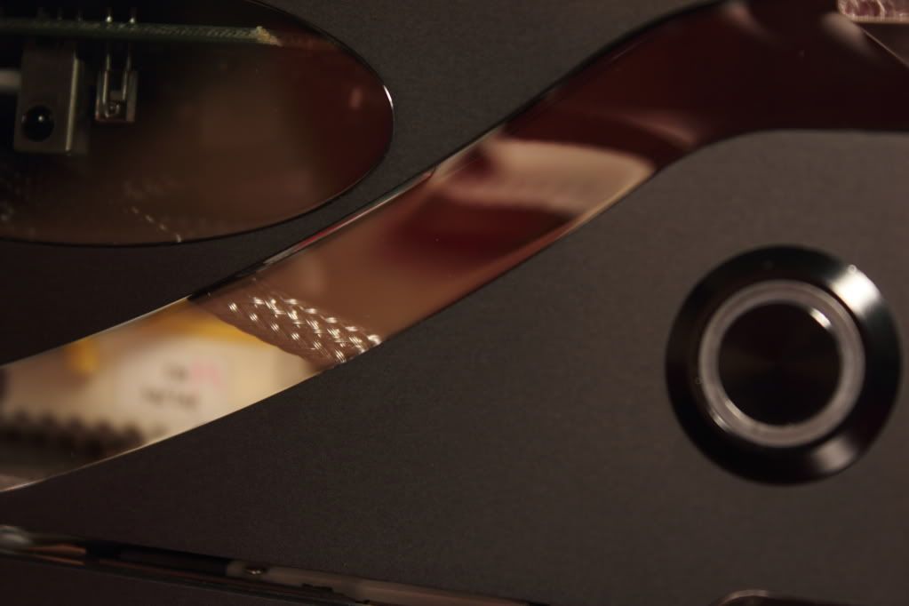
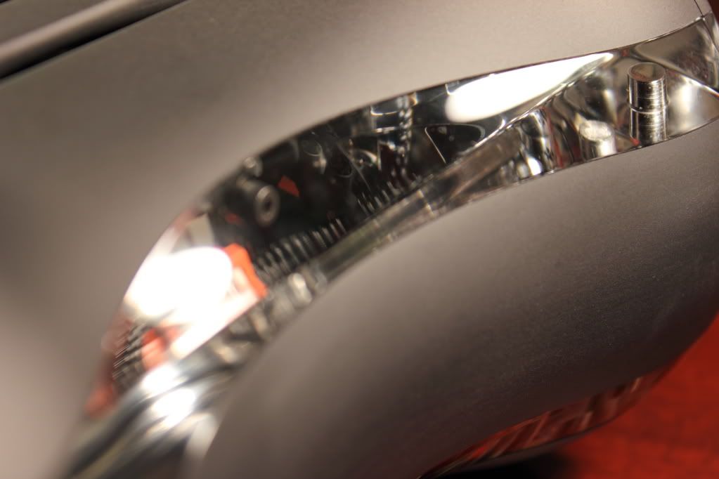
You'll notice the ends of the piece aren't as smooth as the middle. The clamp in the CNC is only so wide, so the ends tend to chatter a little when the tool goes over those parts. It's still smooth to the touch, but what you're seeing is probably 0.001-0.005" variations. Nothing a little sandpaper can't fix.
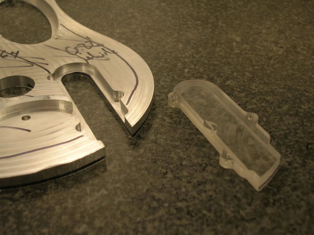
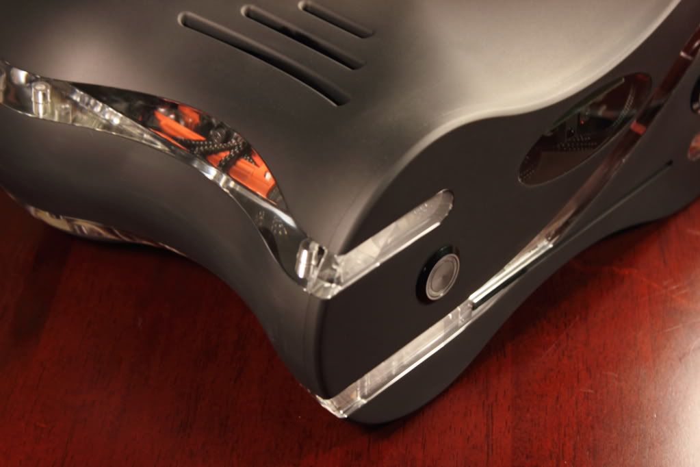
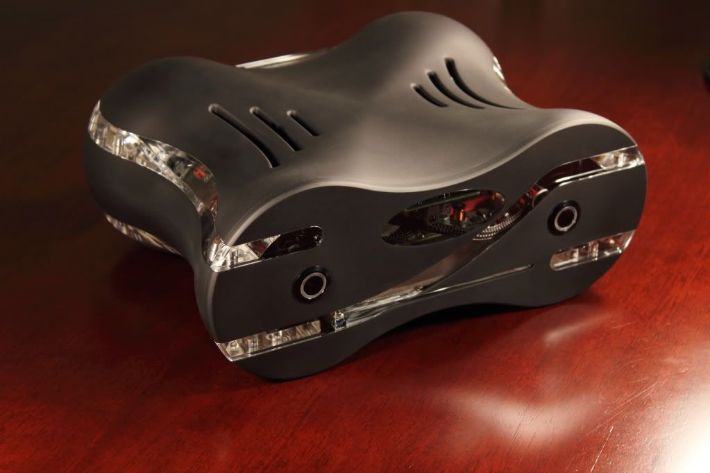
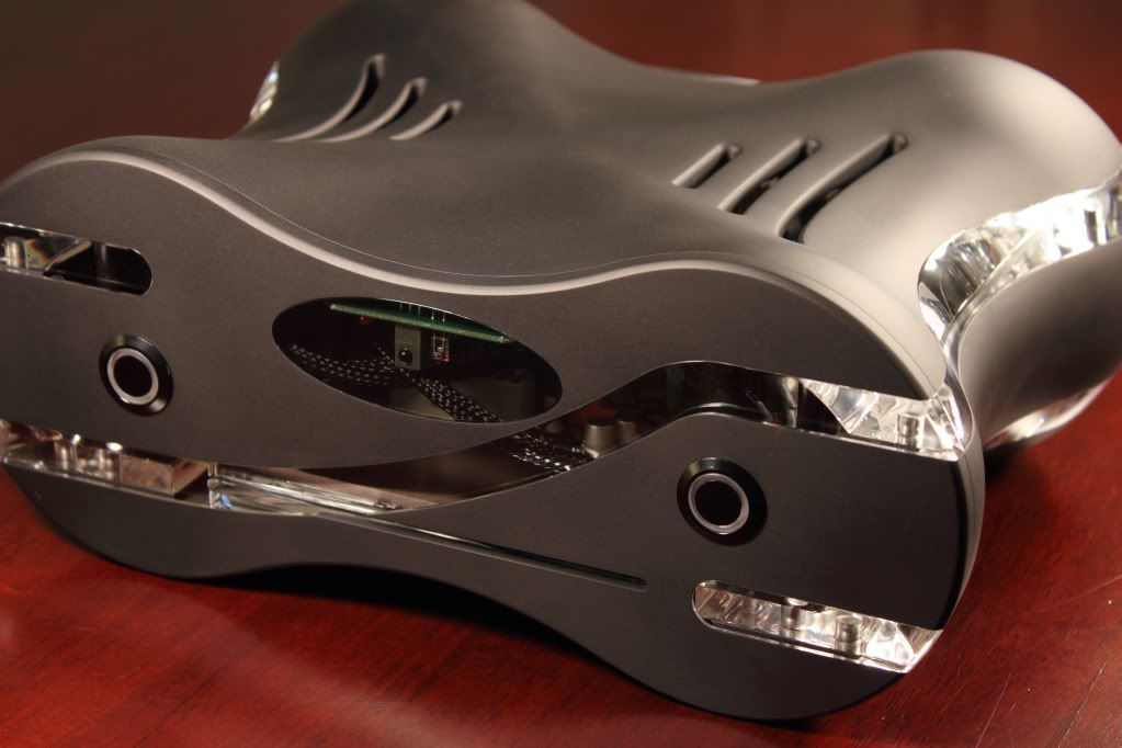
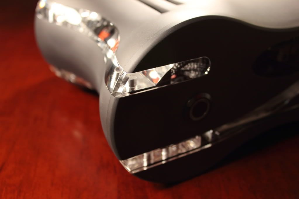
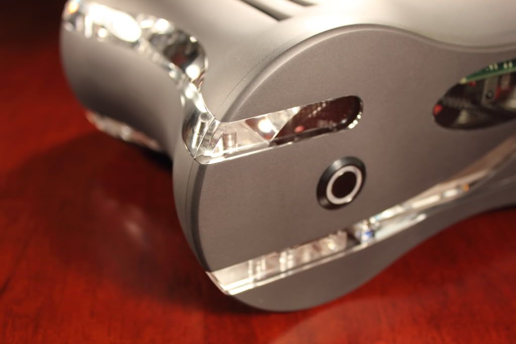
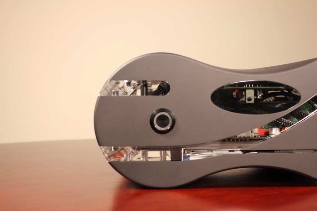
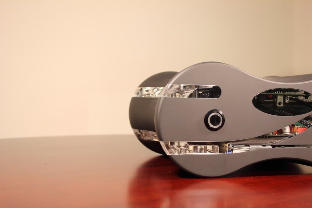
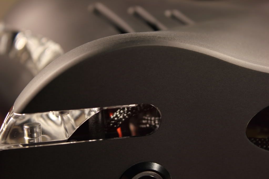
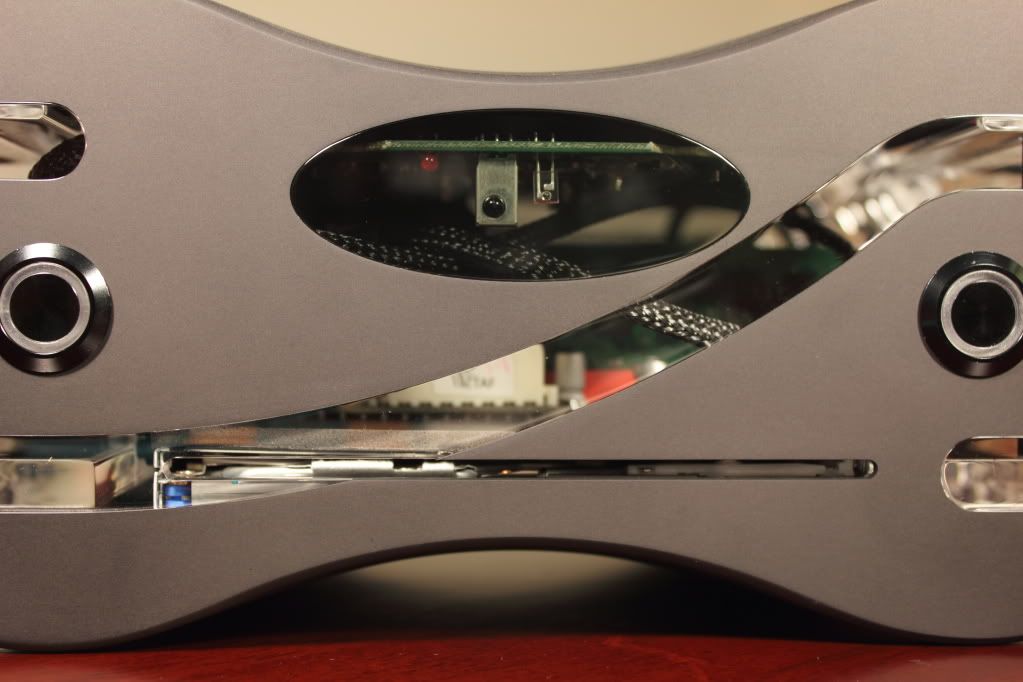
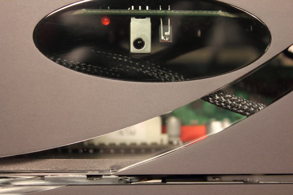
The big oval hole is for some IR-visible plexiglass. I don't like anything external, so I hacked apart a MCE receiver and it will be mounted behind this opening. The two holes on the ends are for vandal switches, one for the power switch and the other for the Blu-ray eject (probably). The slot...well the slot is for ejecting the money that I sank into this project :duh:.
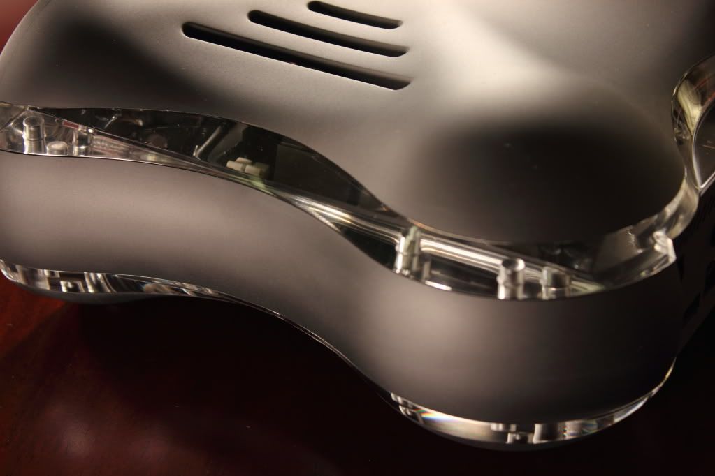
Top Chassis Lid:
This piece is a bit more difficult than the last. First, finding a 1" thick piece of aluminum 100mmx200mm is a tedious task. Not to mention that the shape of this piece is...well, complex. As I'm writing this log on a Friday night, the part has been running since 4ish PM today. Projected time to completion, 20ish hours. That may have something to do with the fact that to smooth out the 'scallops' left by the roughing toolpath, I had a small ball end mill (1/8") make very small steps. If anyone doesn't know much about CNCing, feel free to ask and I will do my best to answer. Disclaimer: I am by no means an expert!
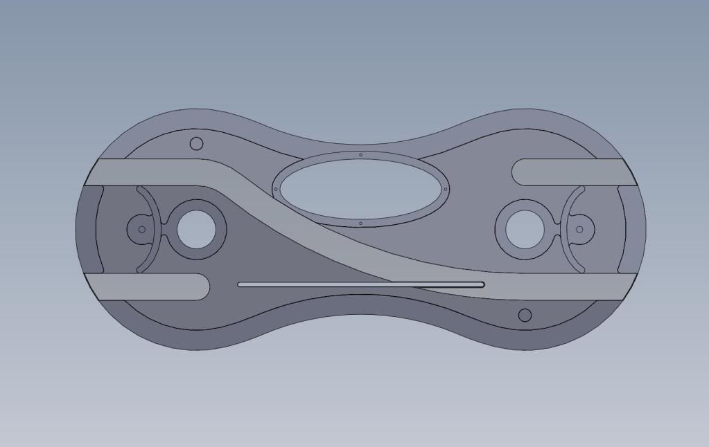
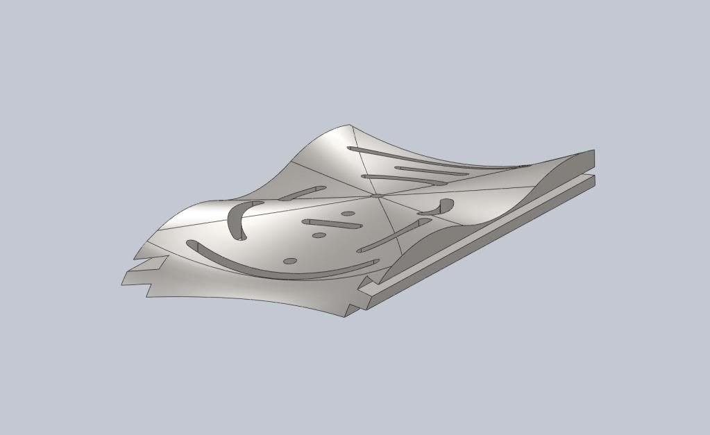
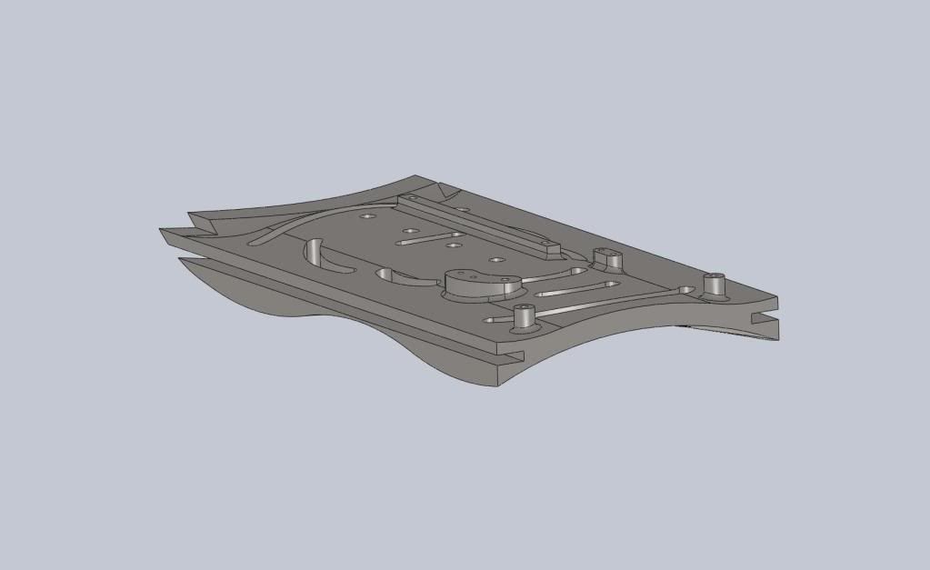
Here's a solid model shot of the piece. I started off by facing each side, then cutting the groove in the sides. Then, the CNC took the spotlight and drilled the holes on the underside of the piece, followed by roughing and finishing.
Solid - Top:
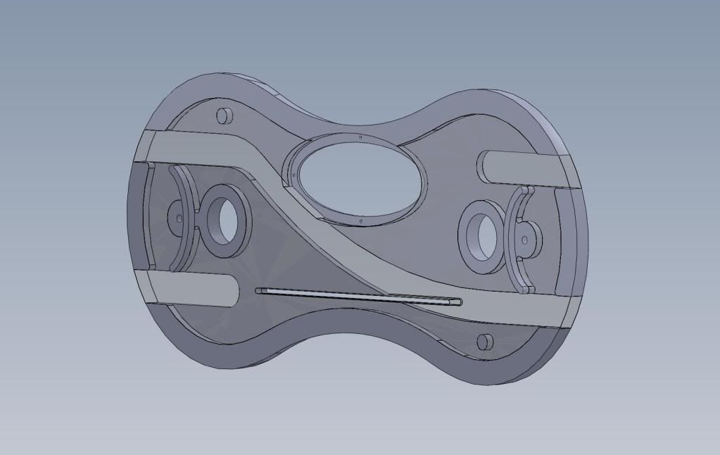
Solid - Bottom
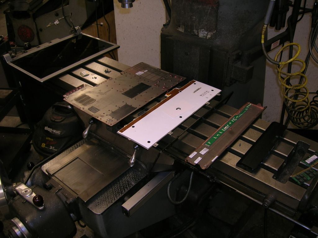
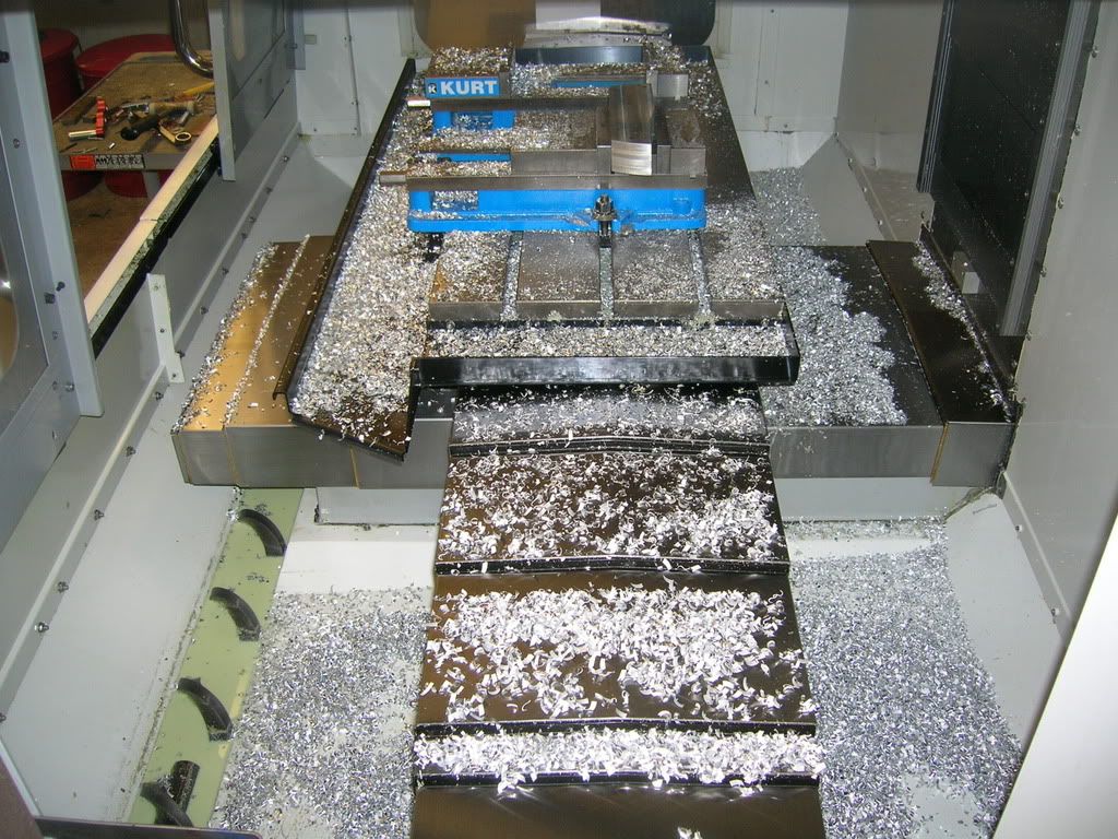
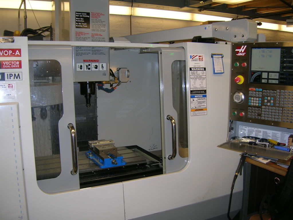
I figured I would provide a picture of the shop I work in, and where this case will (hopefully) come to life. Also, a nice view of the CNC machine is shown.
Machine Shop
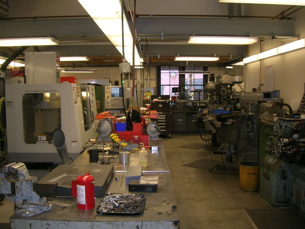
Haas CNC
Top Chassis Lid:
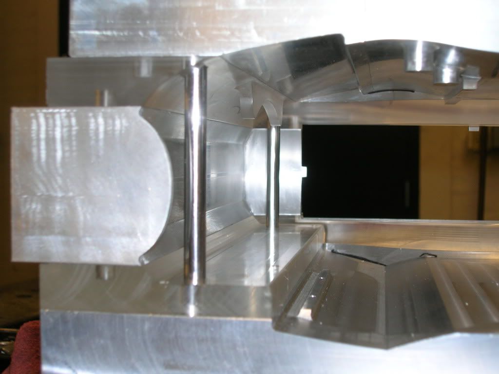
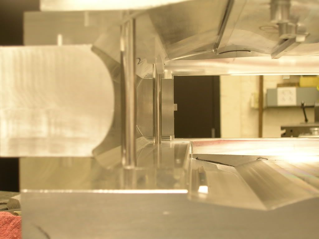
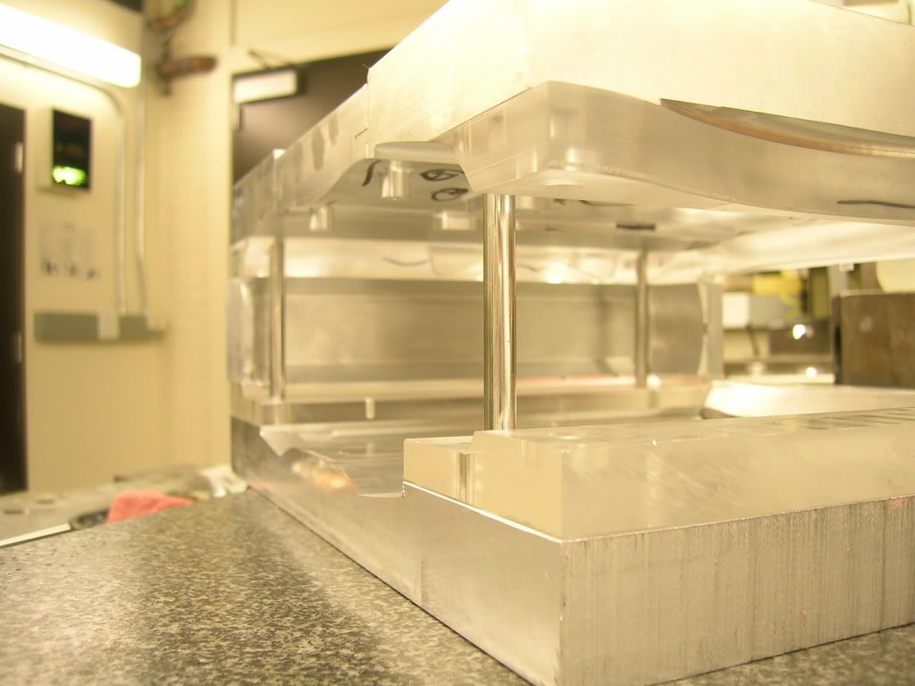
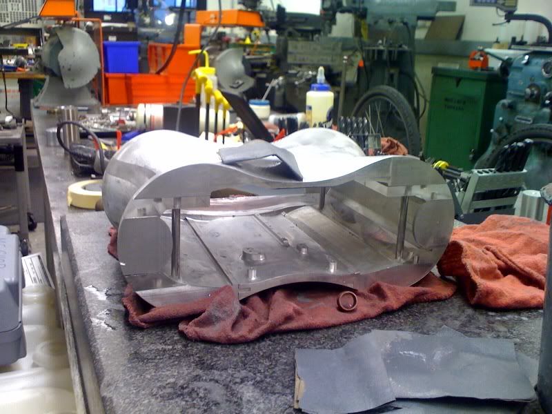
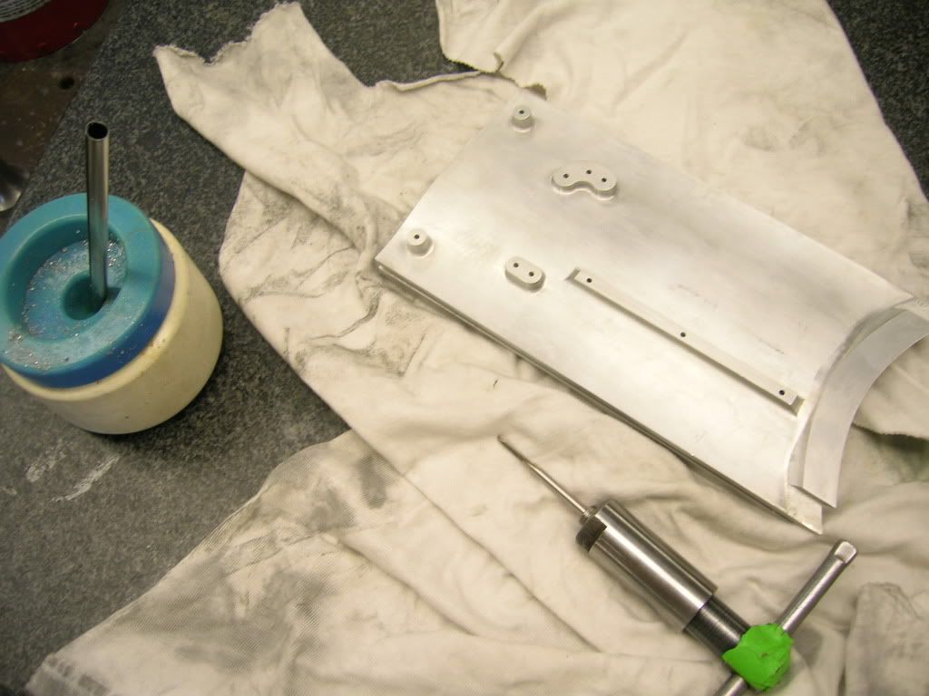
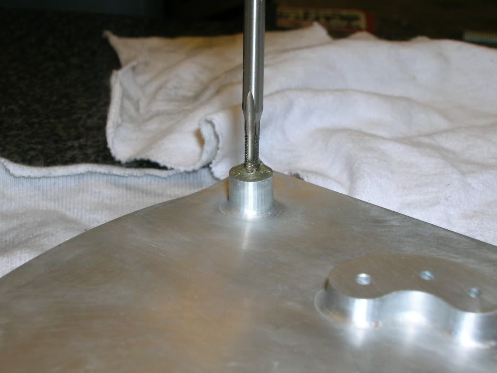
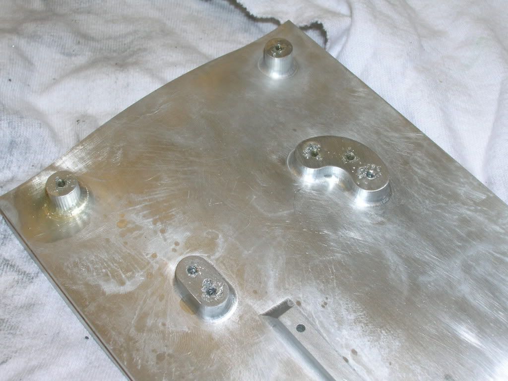
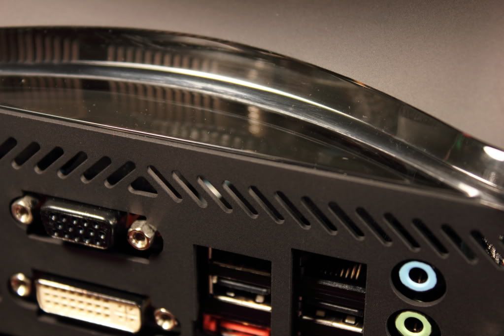
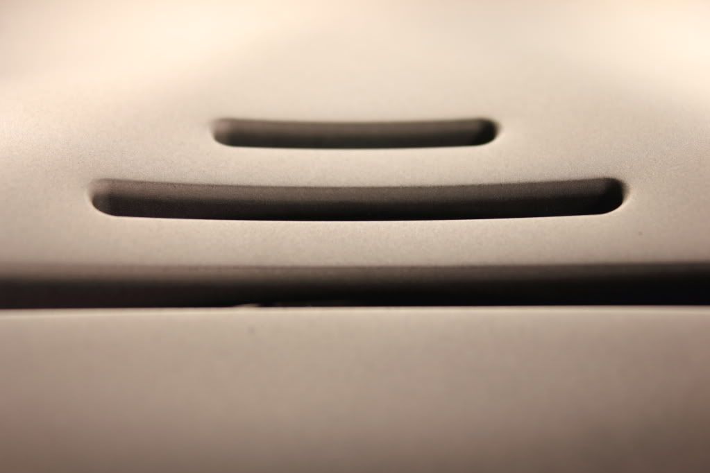
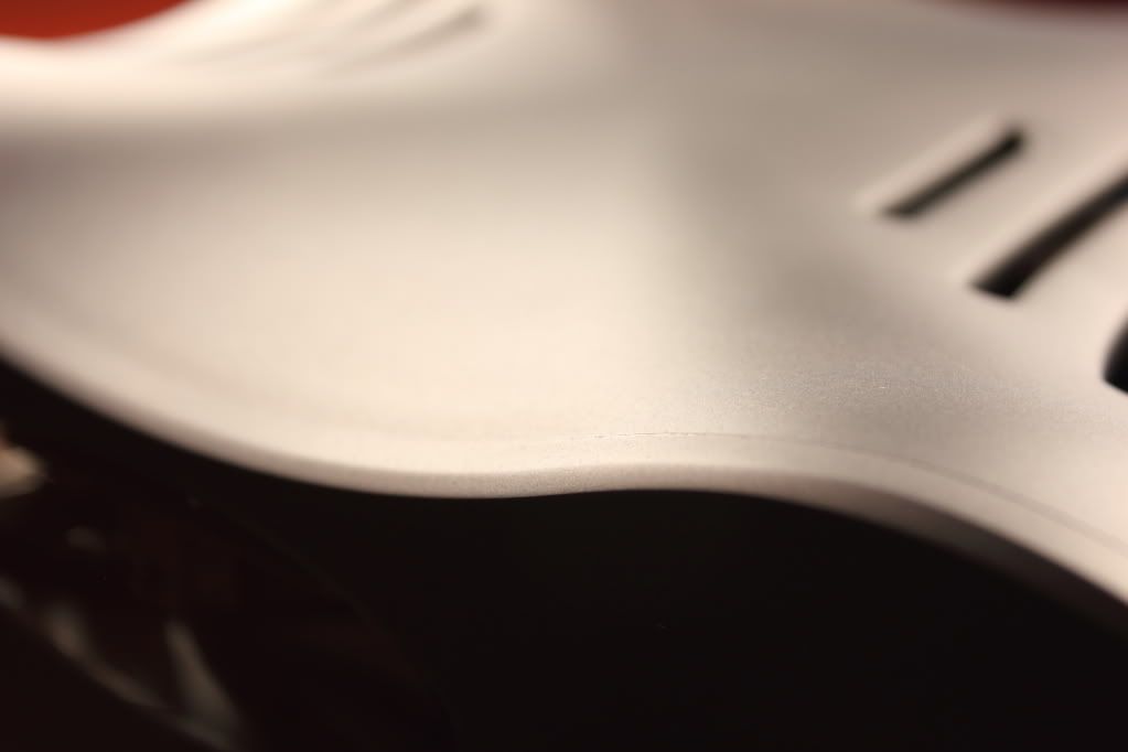
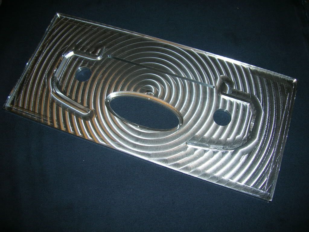
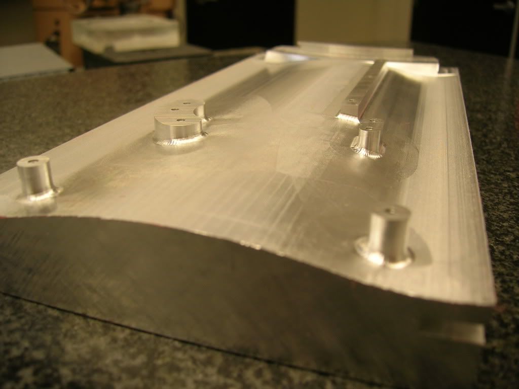
Although I have no progress pictures of this piece, here is the finished bottom of the lid. If you're wondering, this piece took 1.5 hours to rough cut, and ~8 hours to finish.
Finish Pass
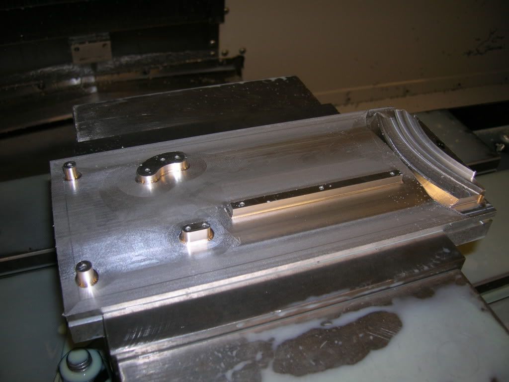
Close Up
Another Close Up
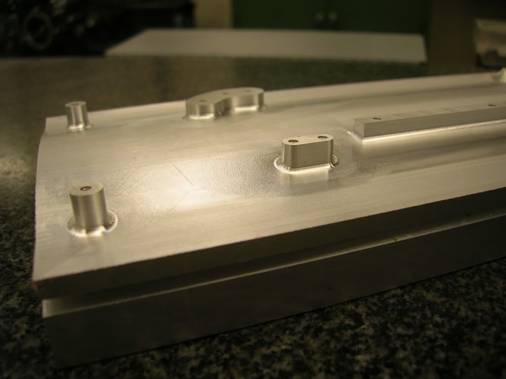
Long Shot
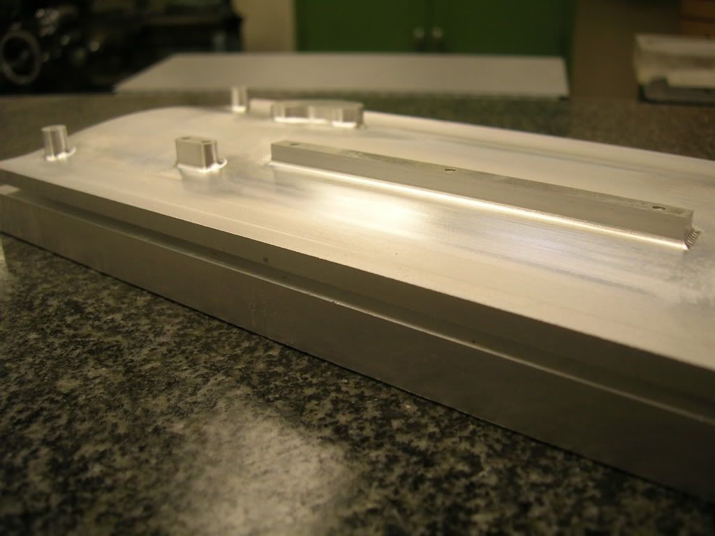
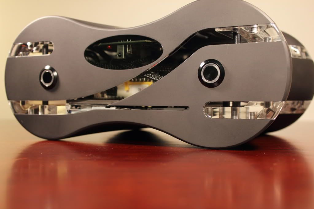
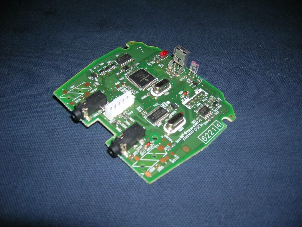
Some of you may wonder what the protrusions and holes are for. The long rectangular protrusion is for the hard drive mount, which can (sort of) be seen in the Solidworks drawings in my previous post. The circular and goofy looking shape is for my IR receiver circuit board! The board looks like so:
IR Circuit Board
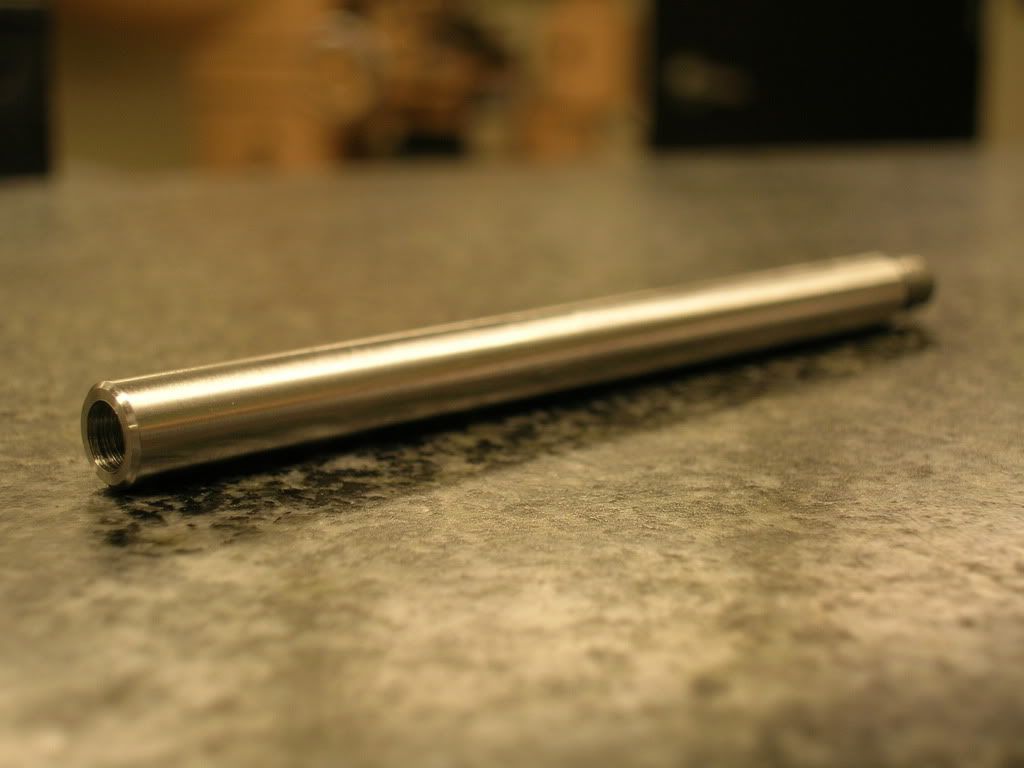
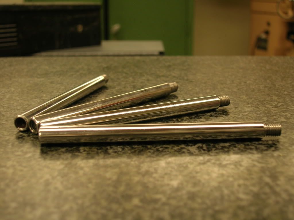
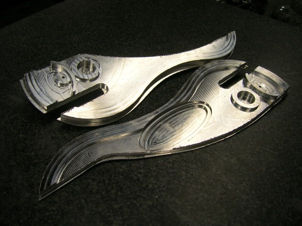
Top Slices:
Since this case can't be comprised of a single block of aluminum, I chose to separate it into sections. It's basically an inch slice from the top of the case, which results in 2 separate pieces.
Solidworks Top Slices
Solidworks Top Slices
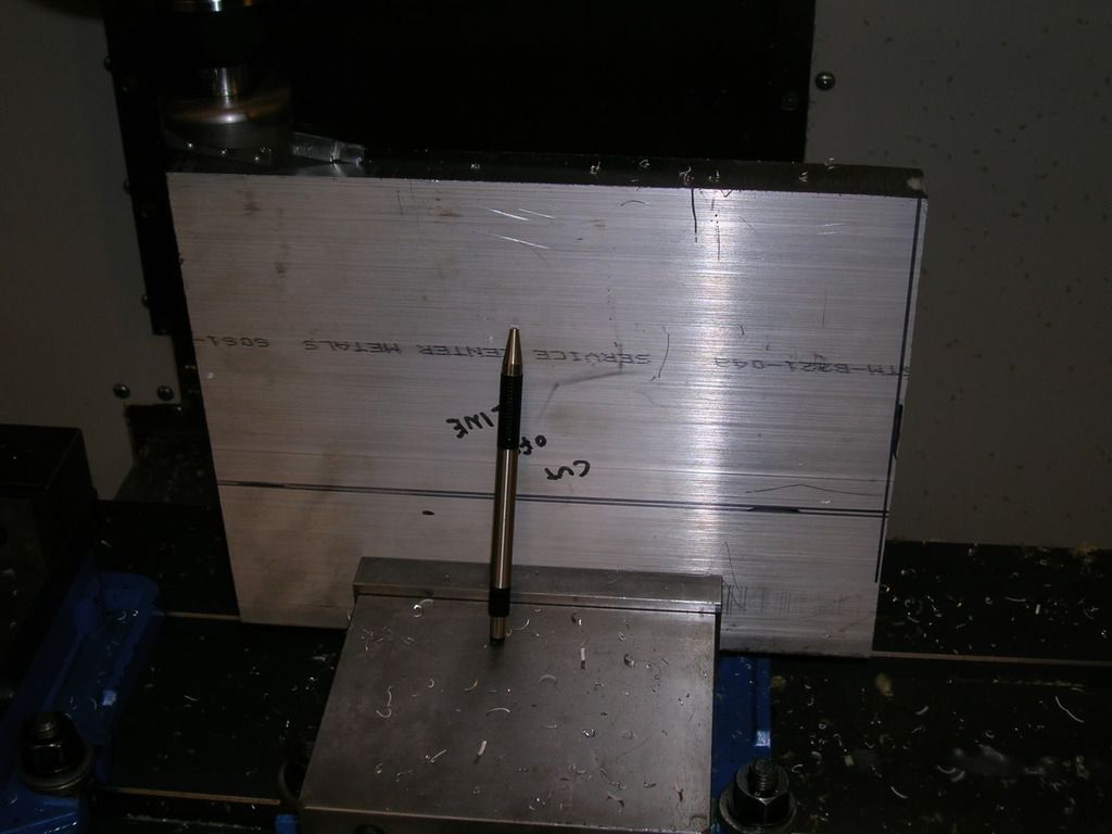
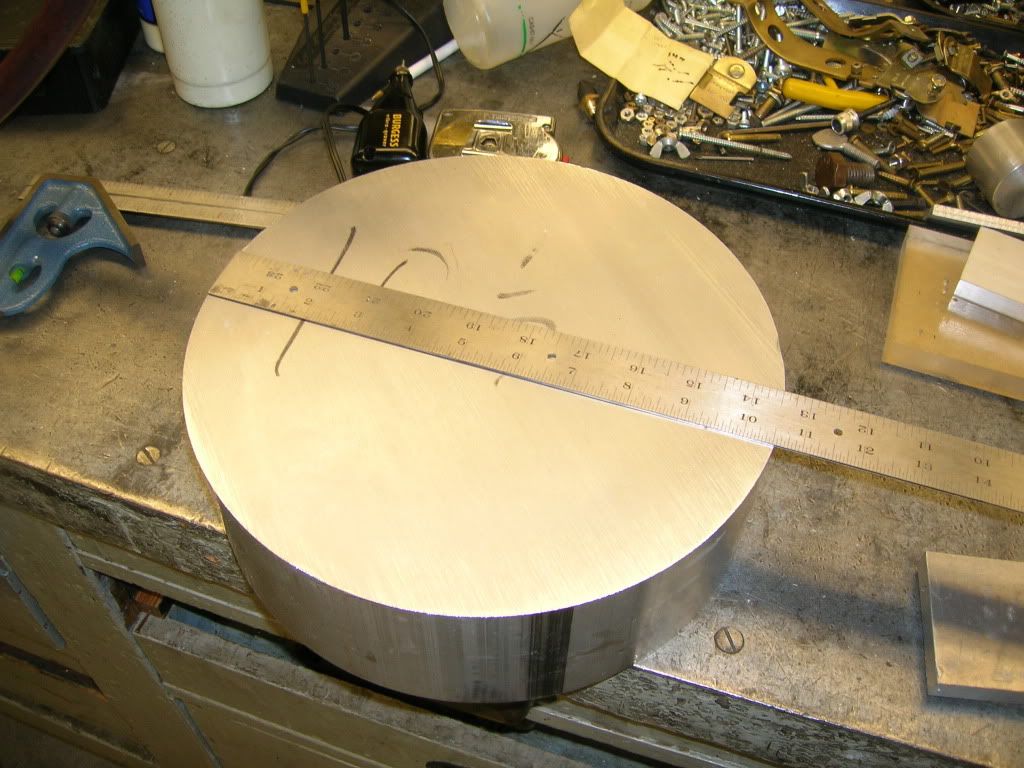
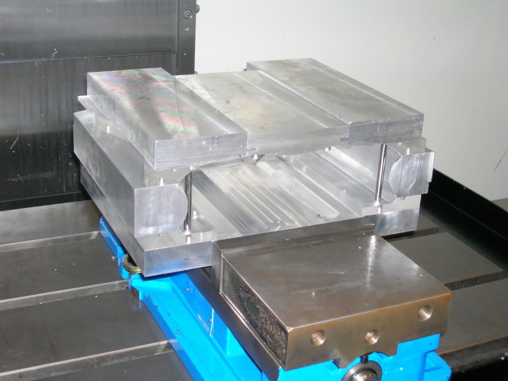
The piece starts out as such...just a simple block of aluminum.
Aluminum Block
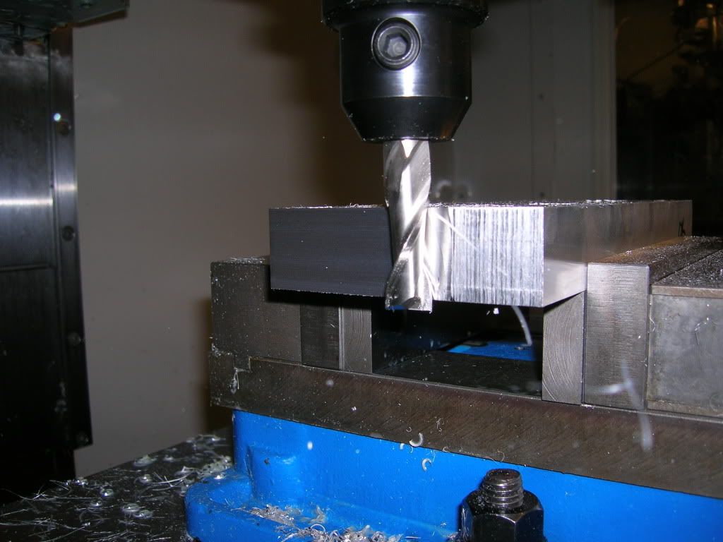
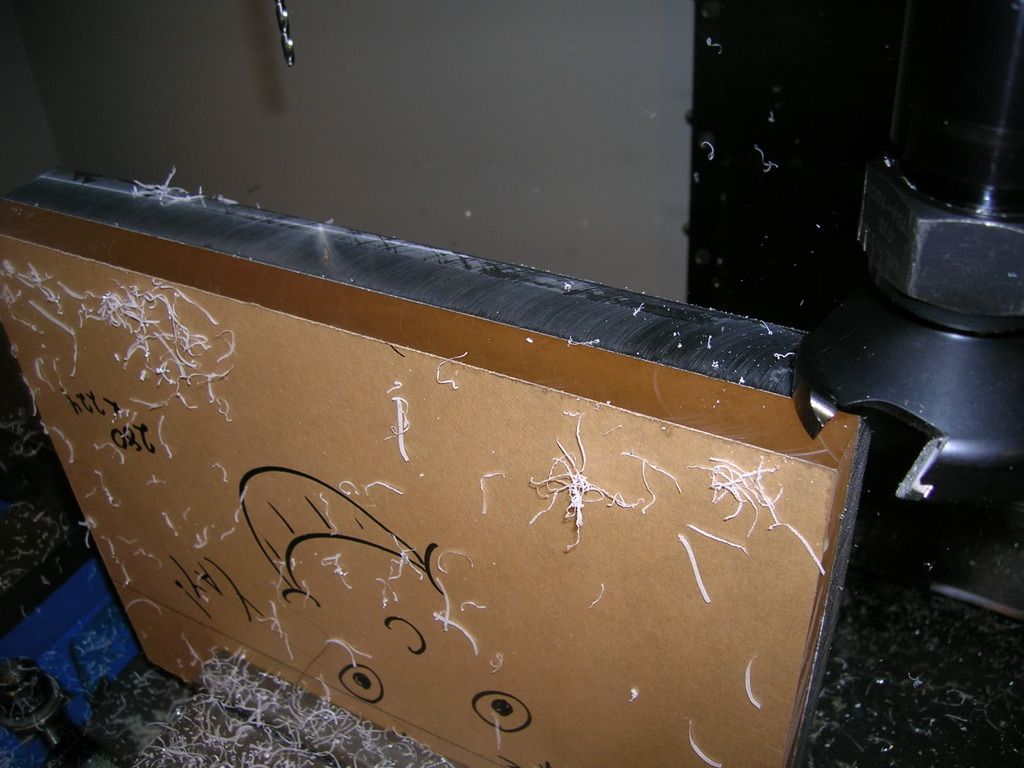
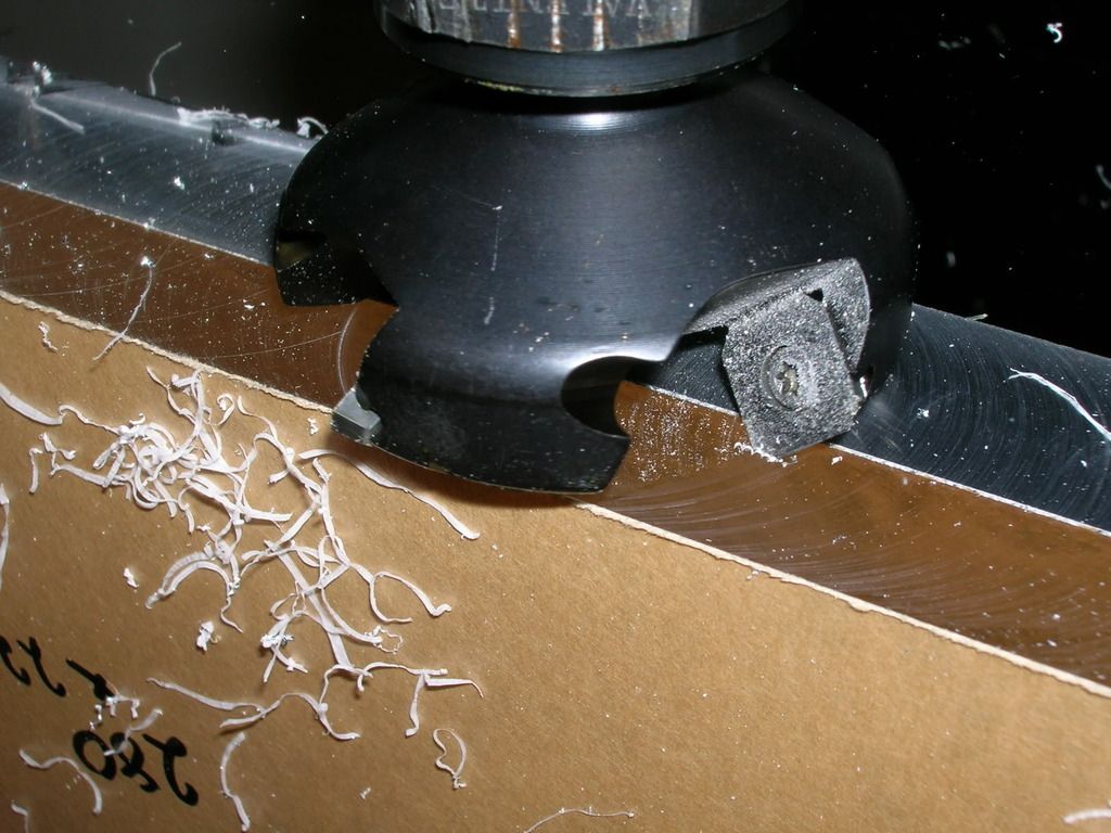
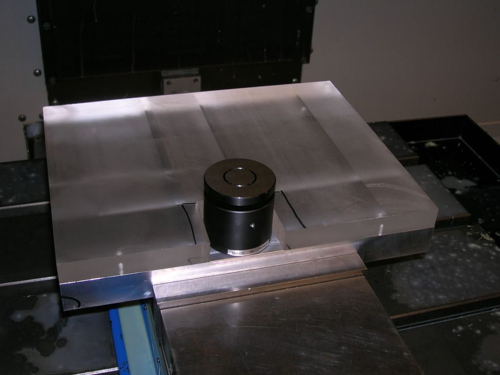
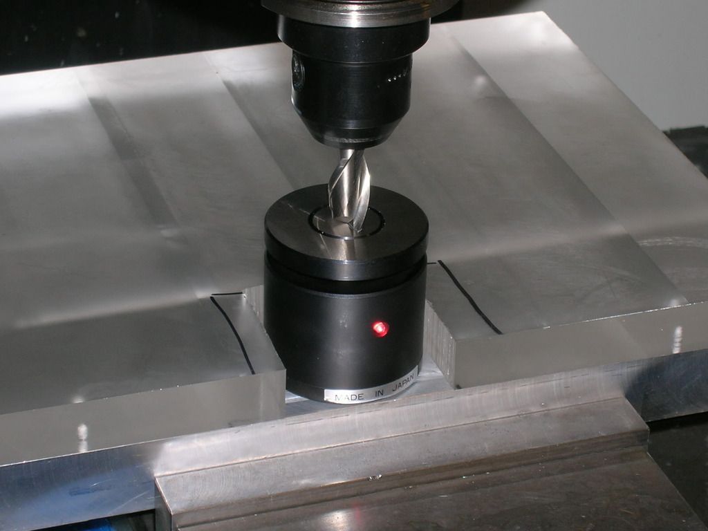
Then, off to facing and edging the piece so everything is level.
Multi-head Cutter
Fly Cutter
End Facing
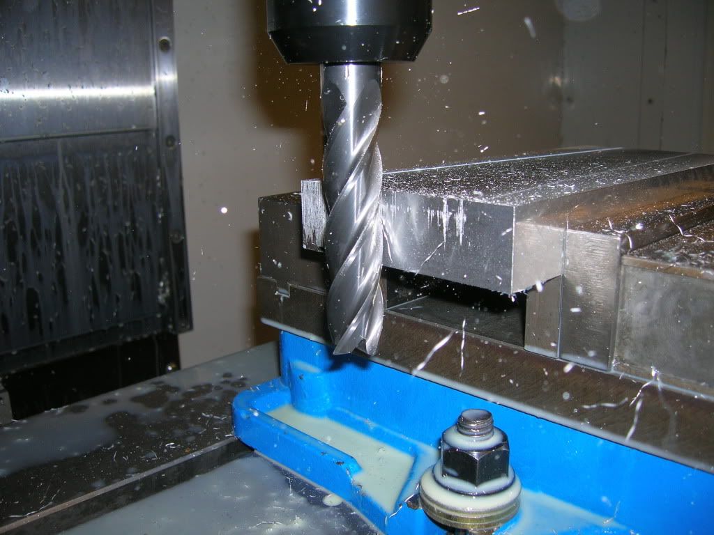
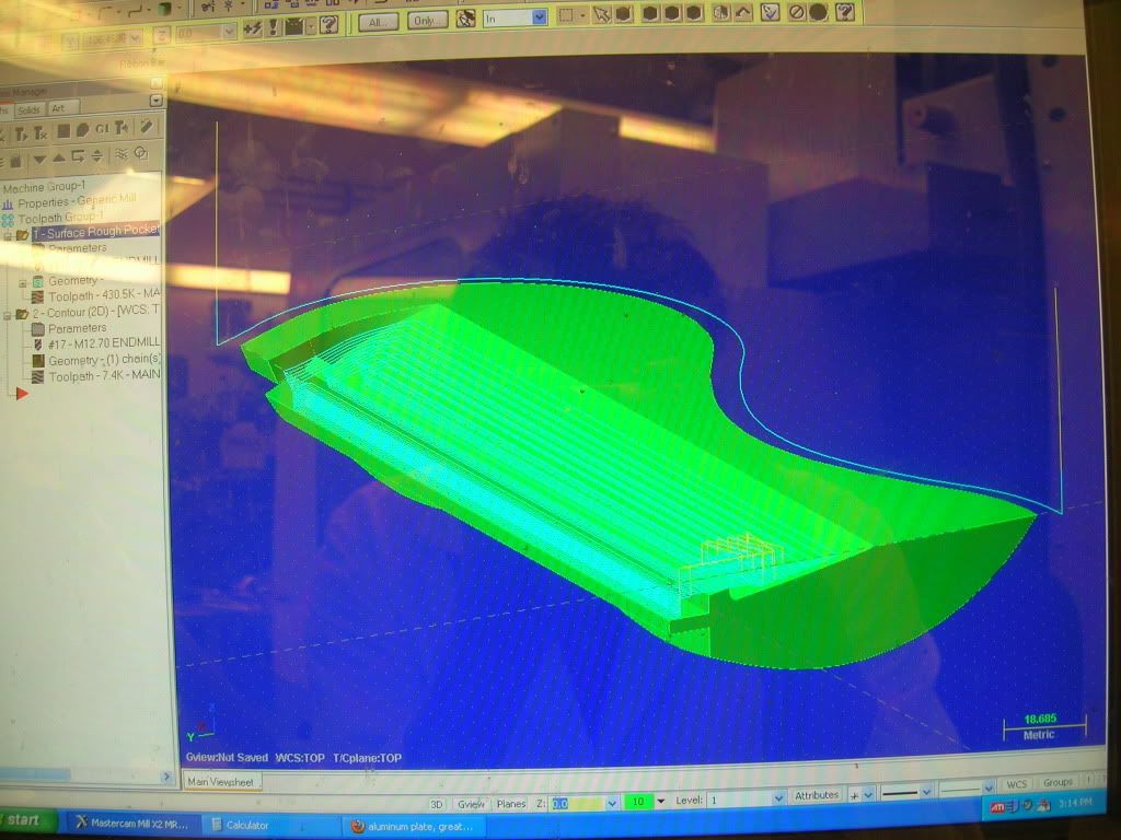
Then, off to Mastercam!
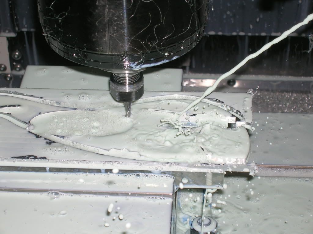
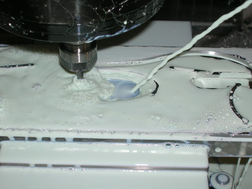
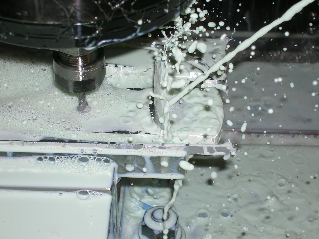
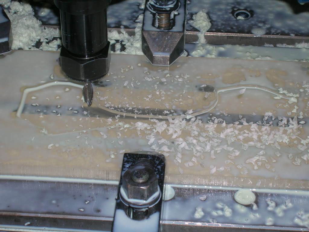
Mastercam Toolpaths
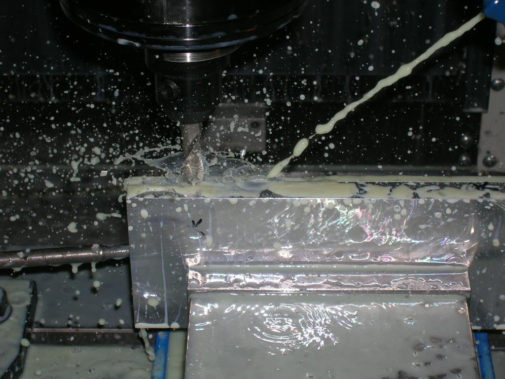
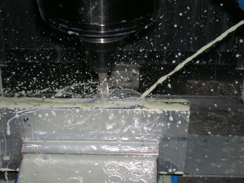
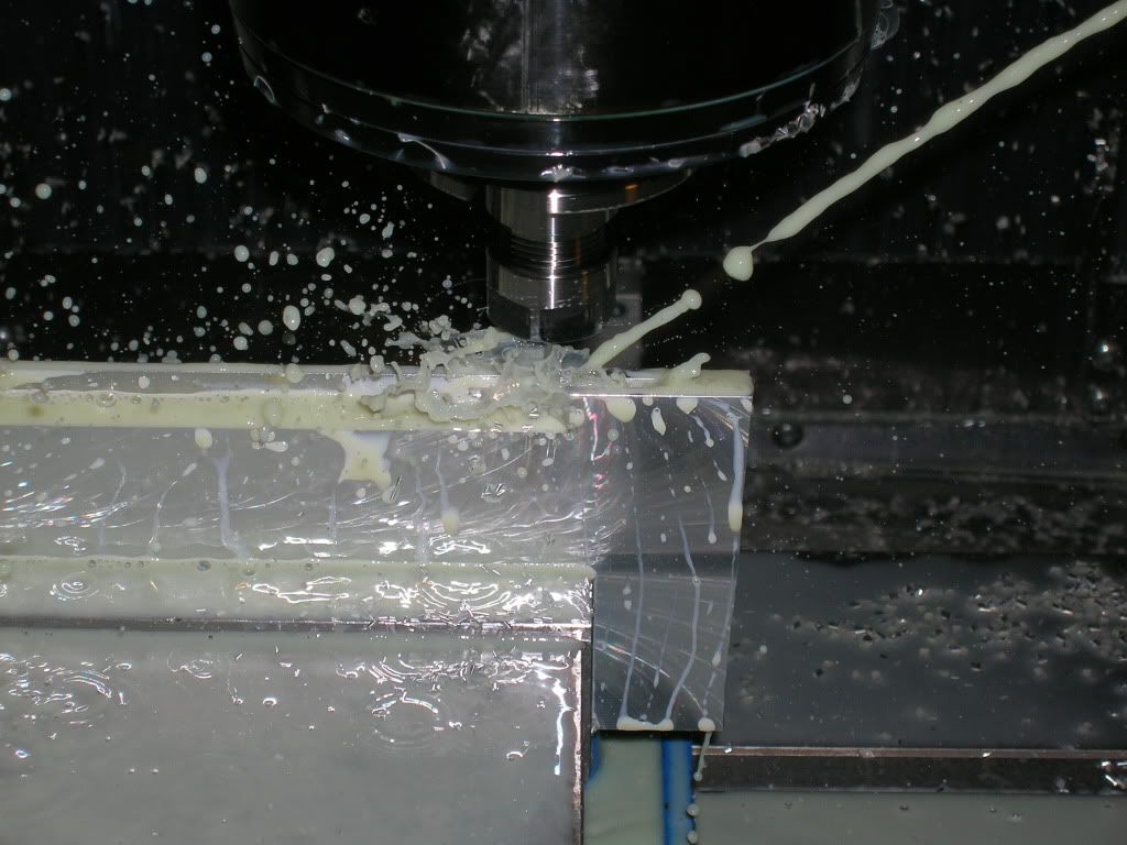
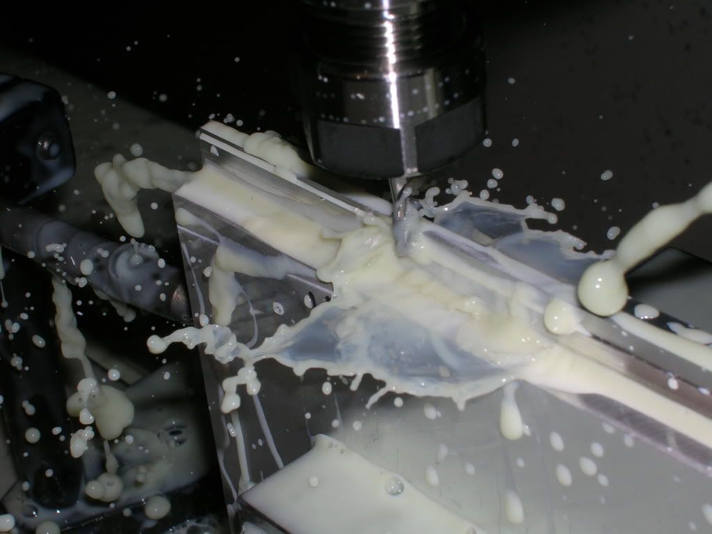
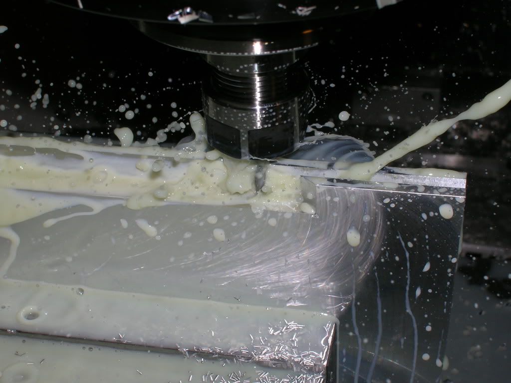
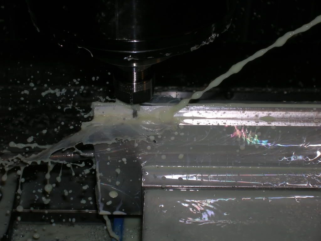
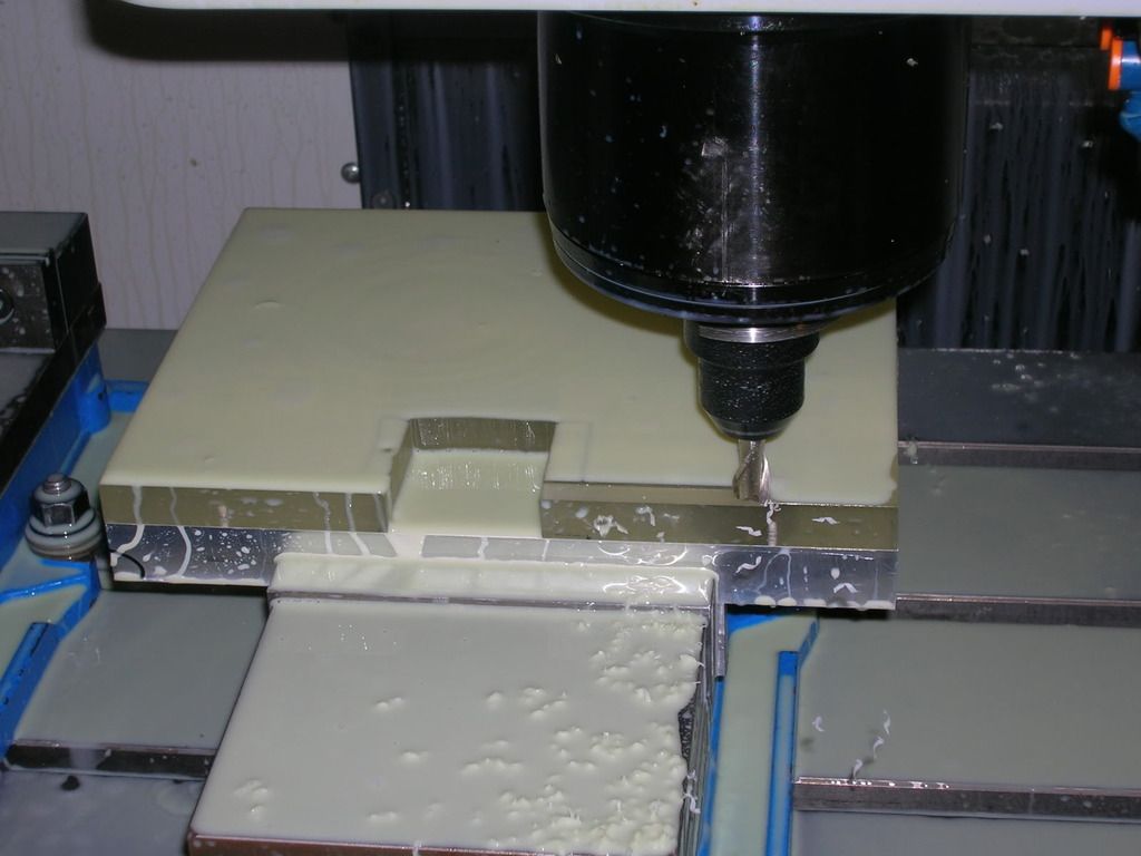
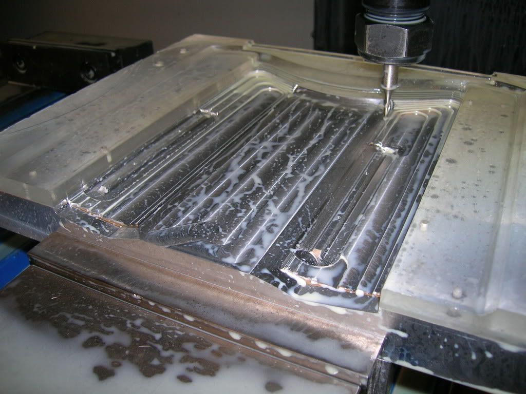
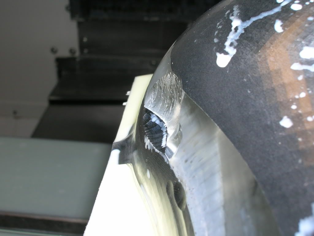
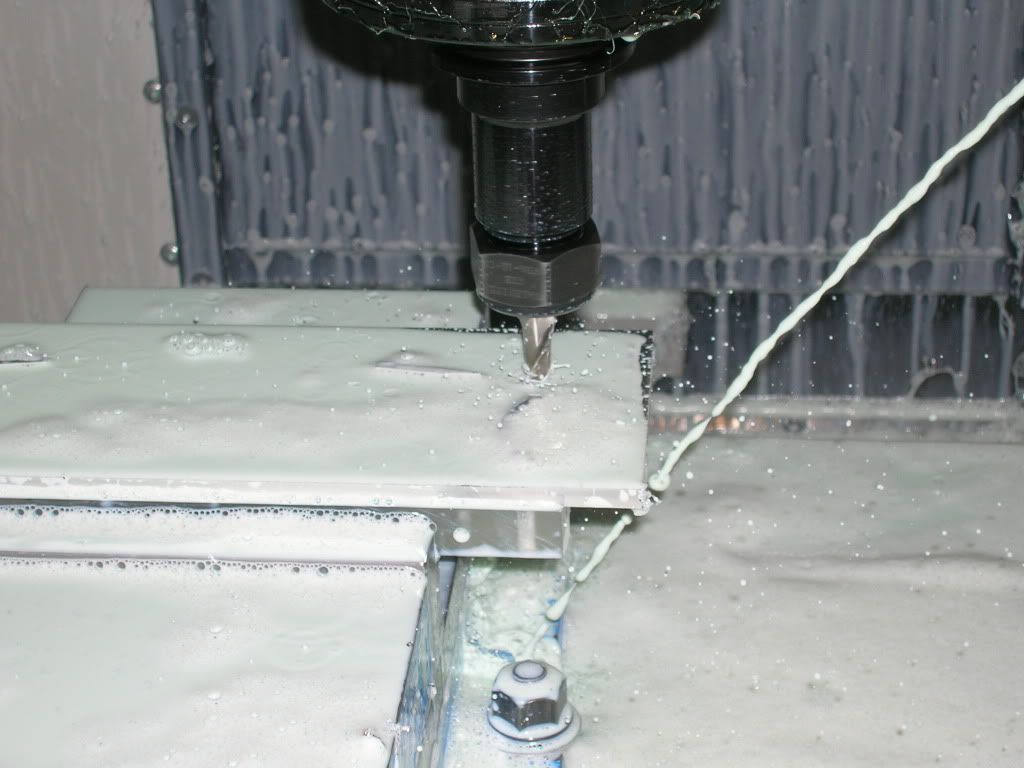
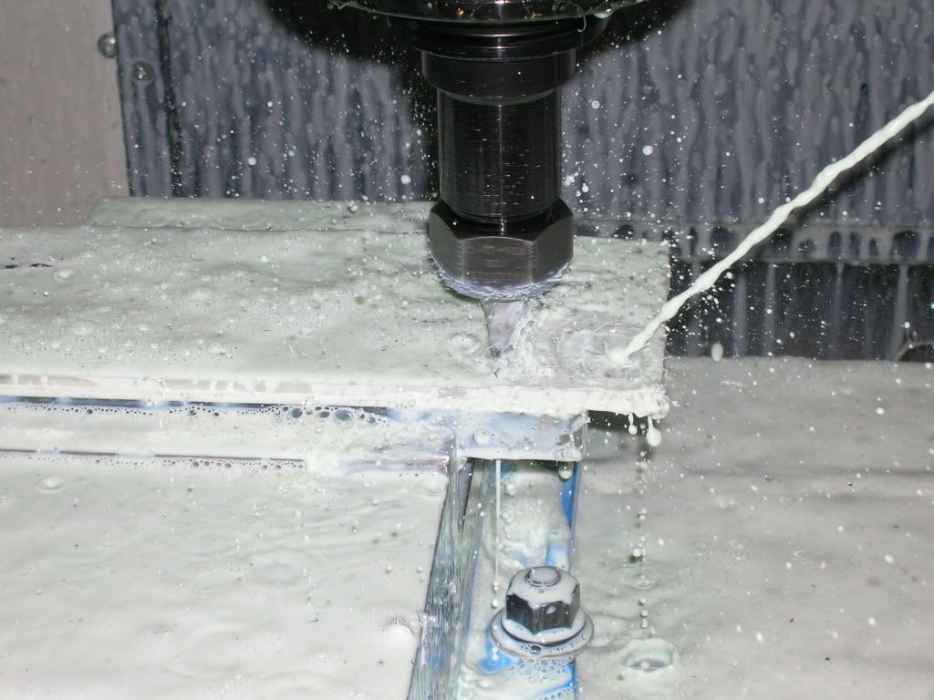
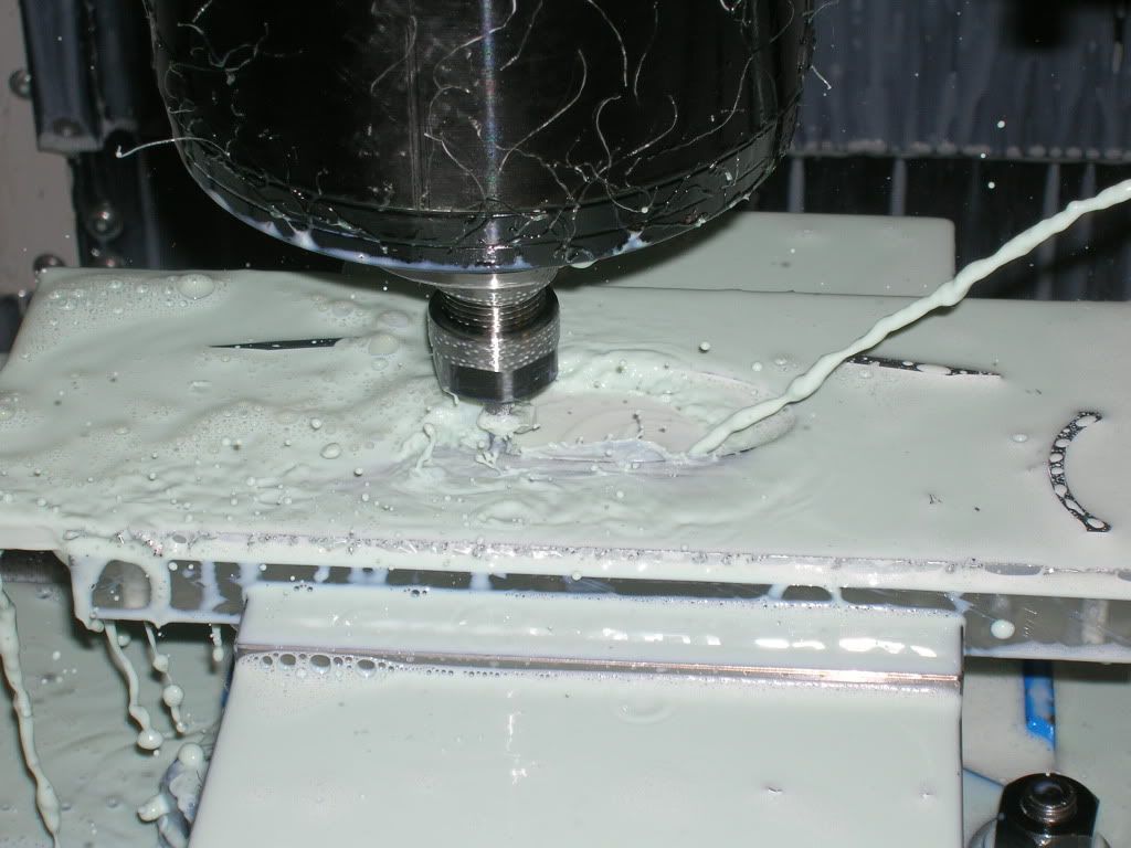
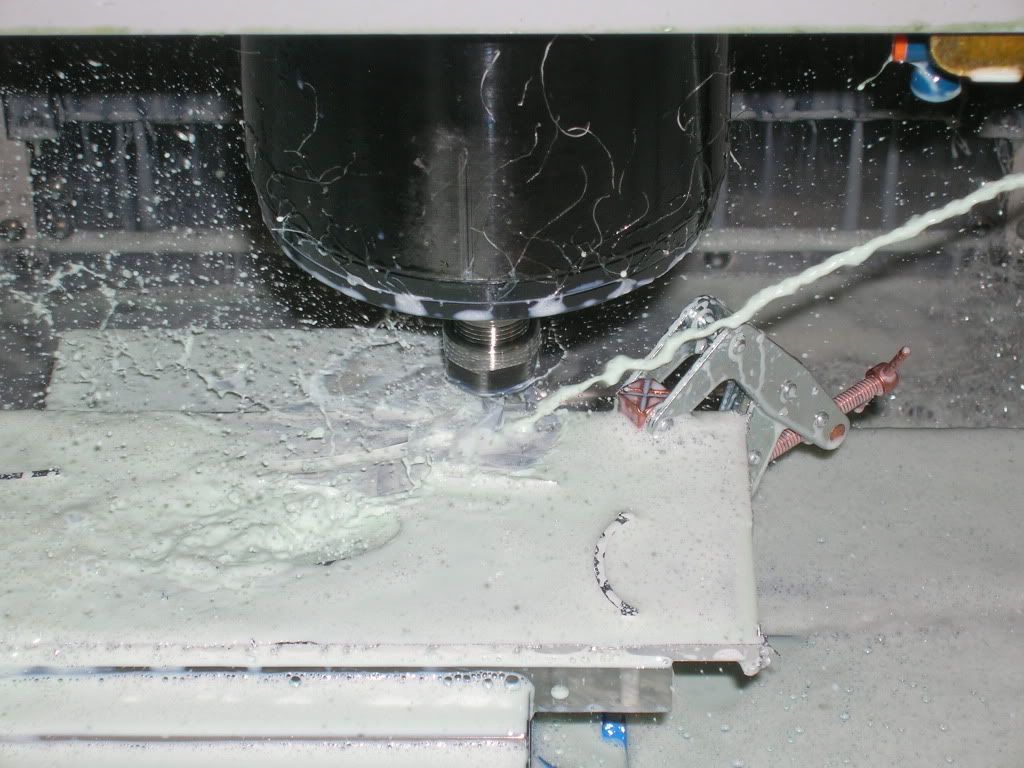
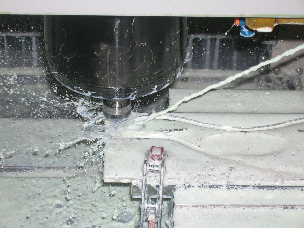
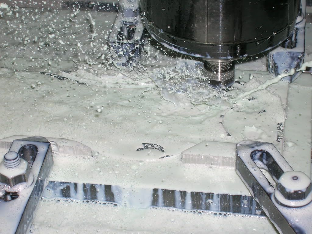
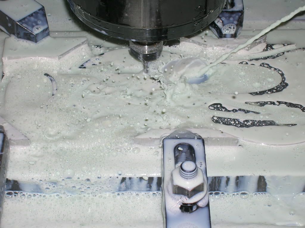
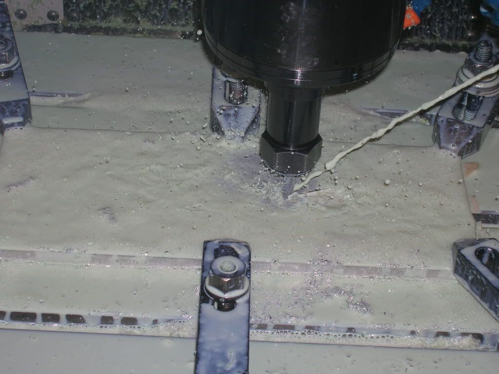
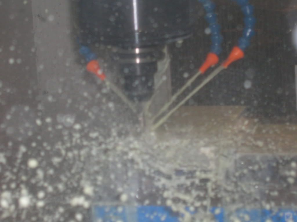
Absolutely nothing visible through the filthy plastic windows and coolant.
Coolant Shot
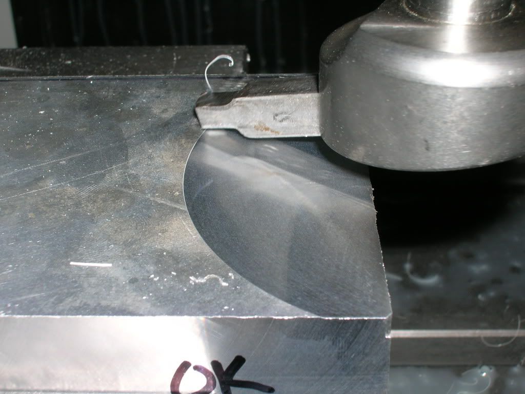
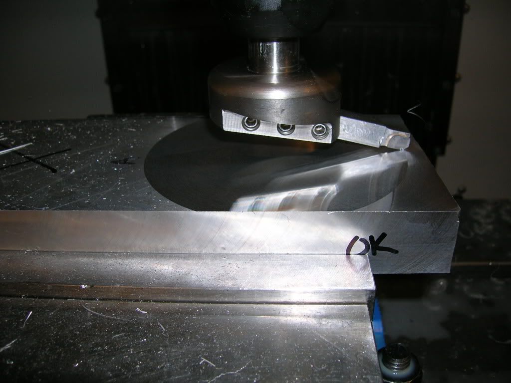
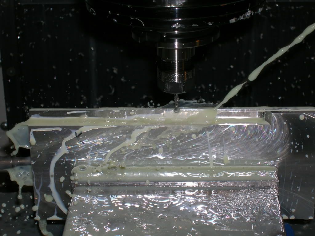
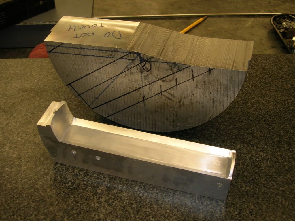
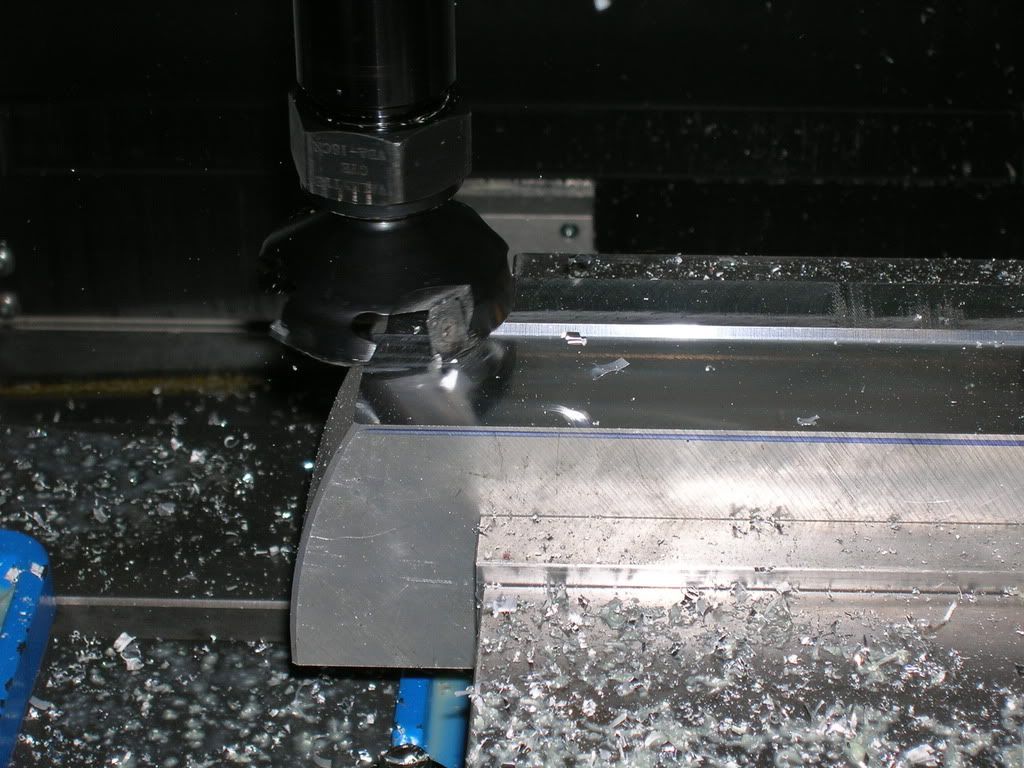
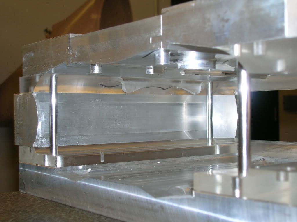
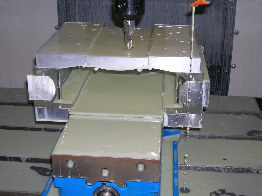
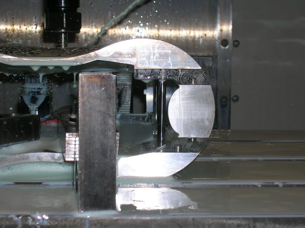
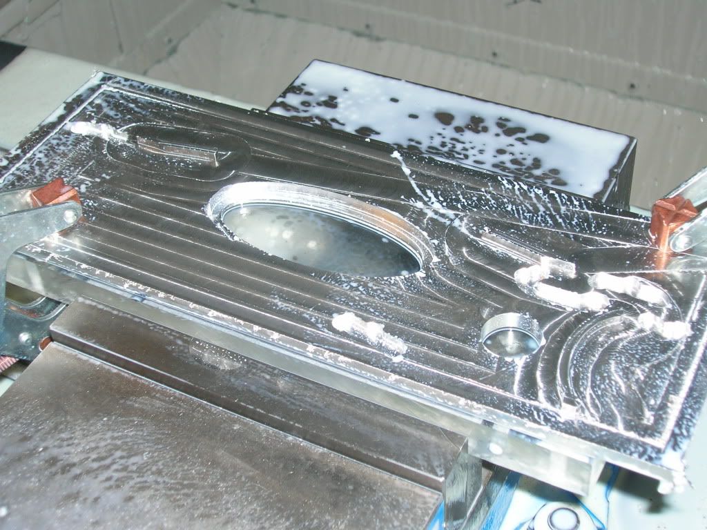
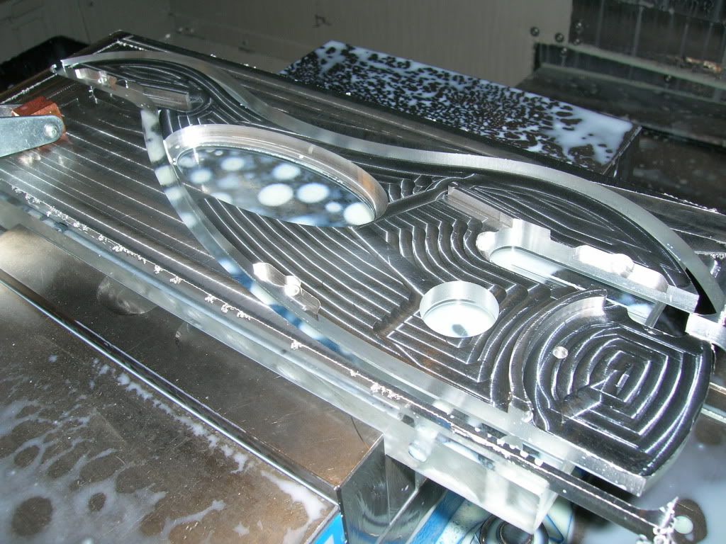
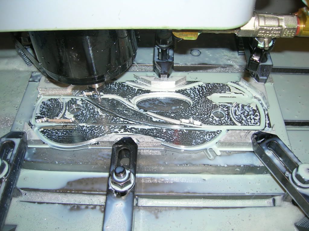
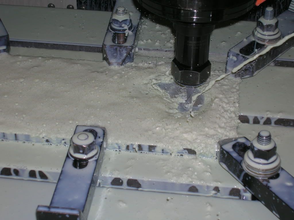
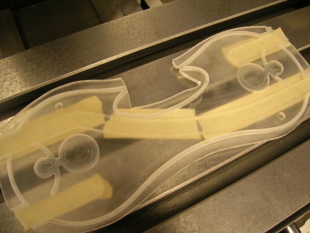
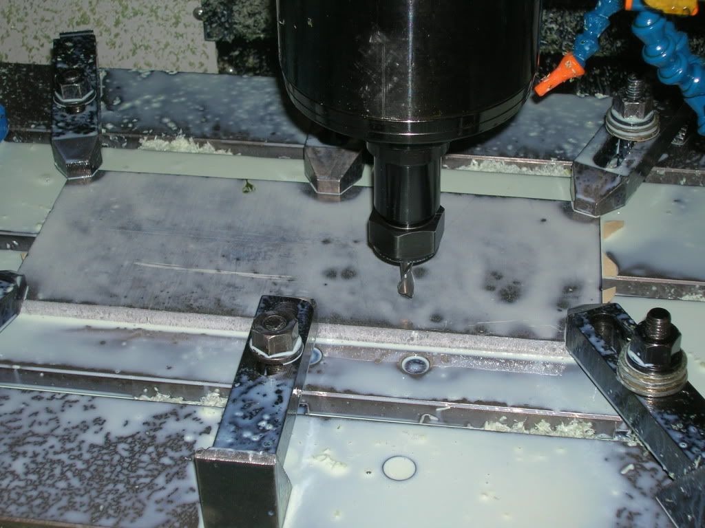
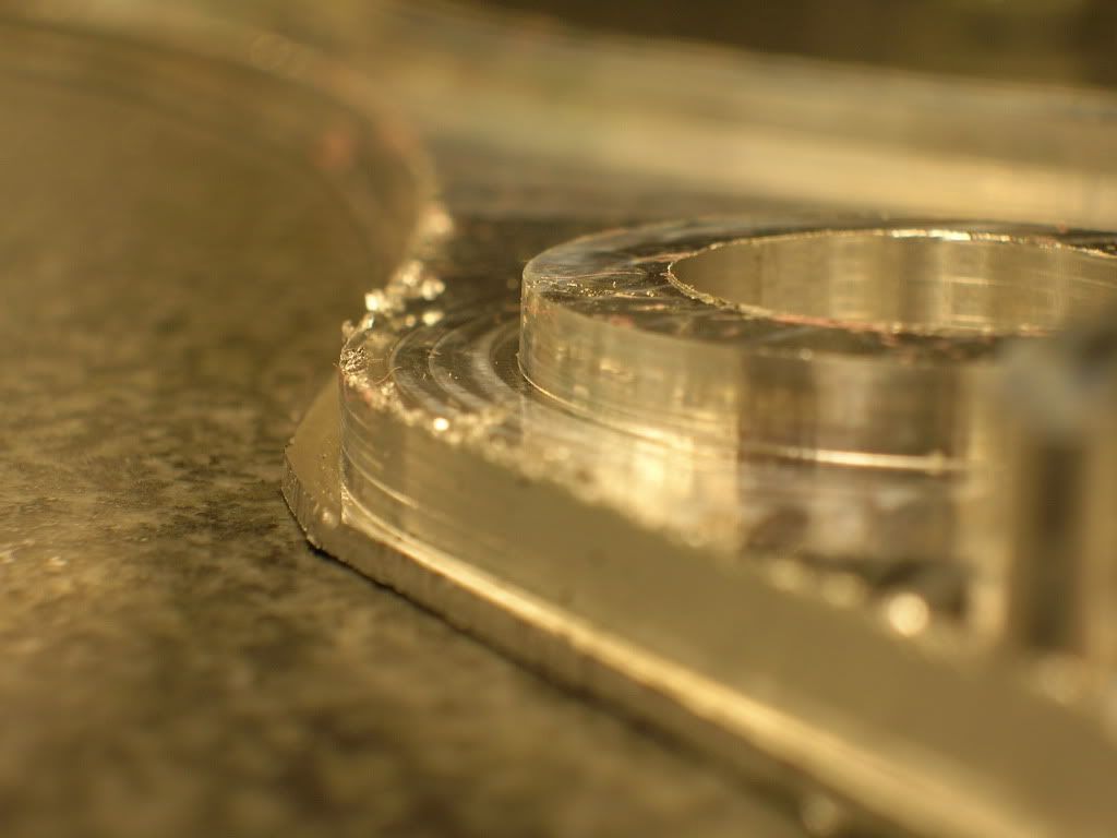
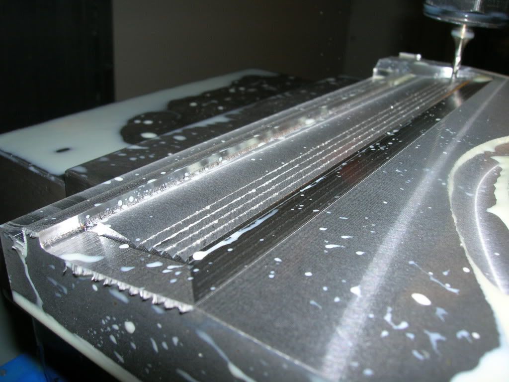
After the roughing paths, this is what is left. Then, we finish it with a smaller ball end mill.
Finished Roughing
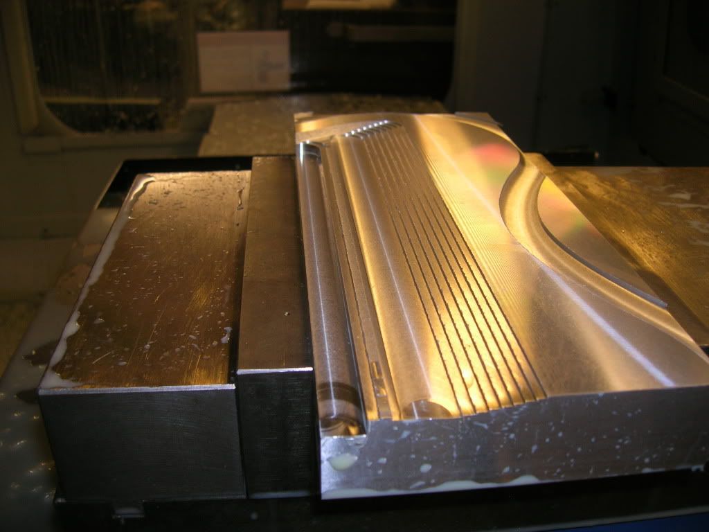
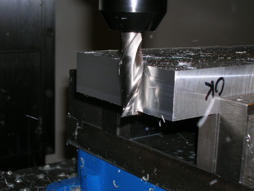
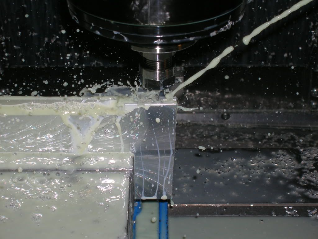
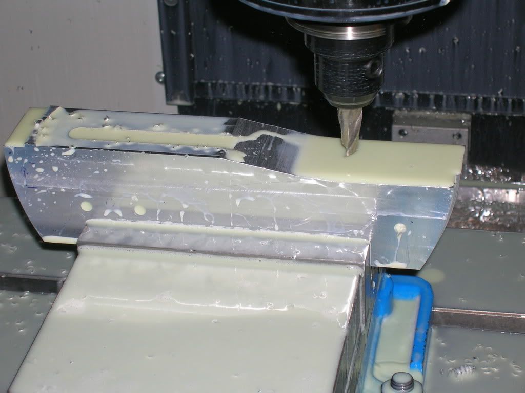
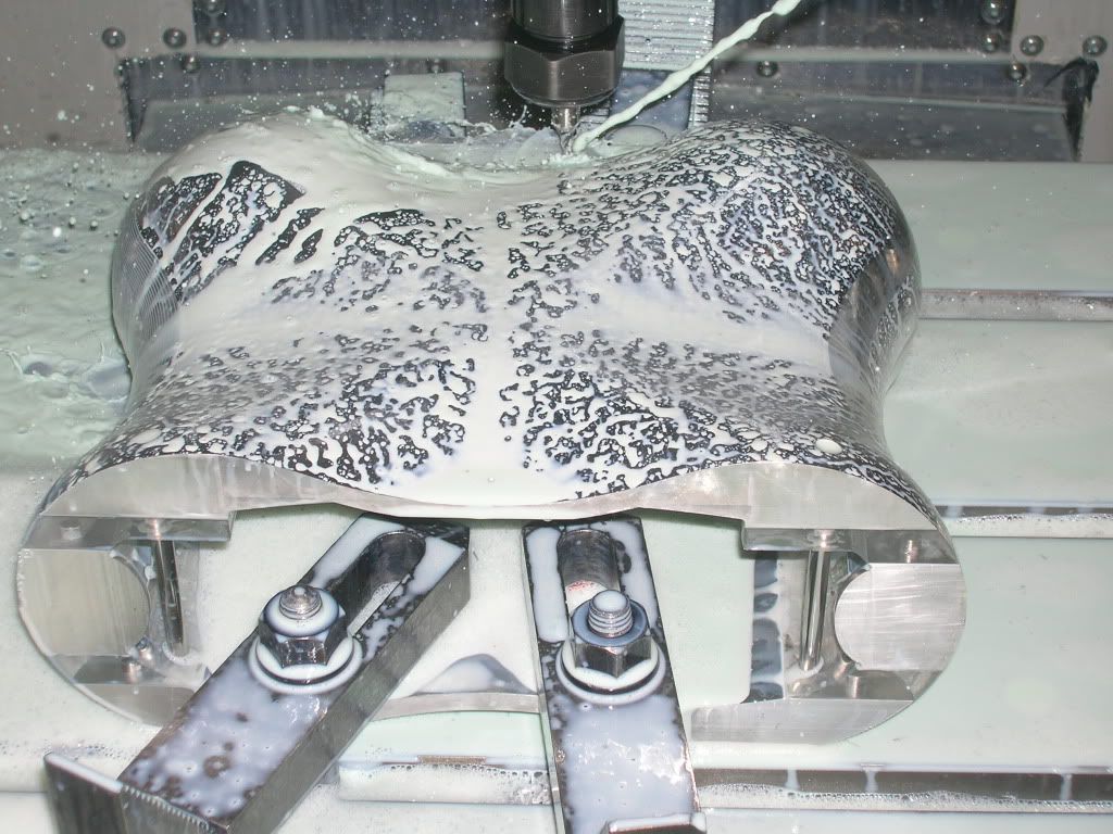
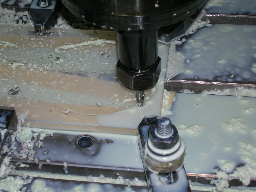
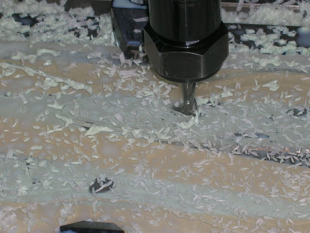
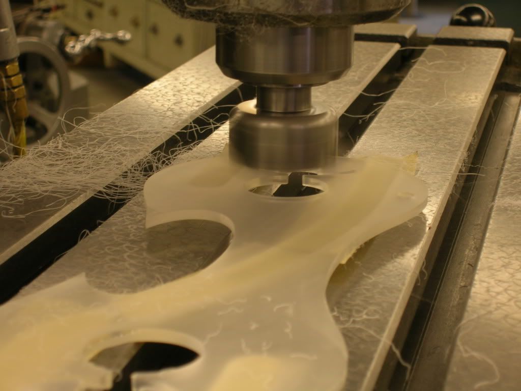
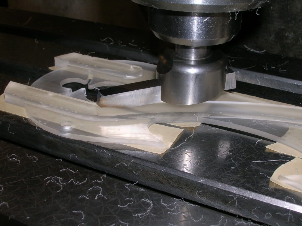
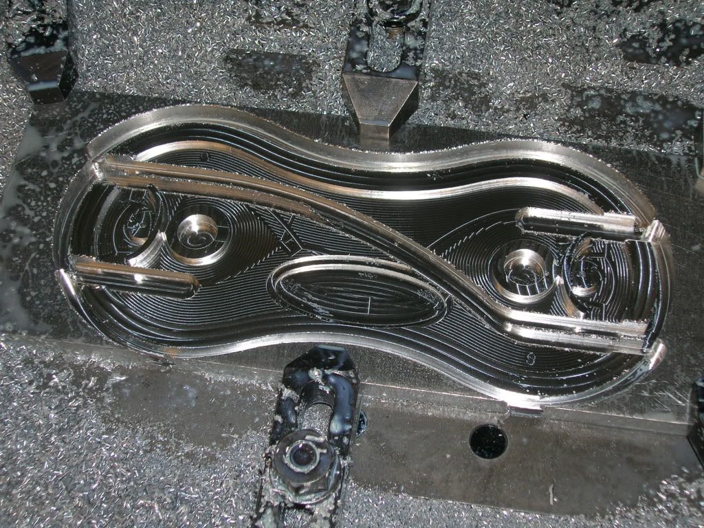
Halfway through the finishing process.
Half Finished
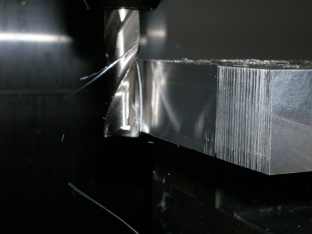
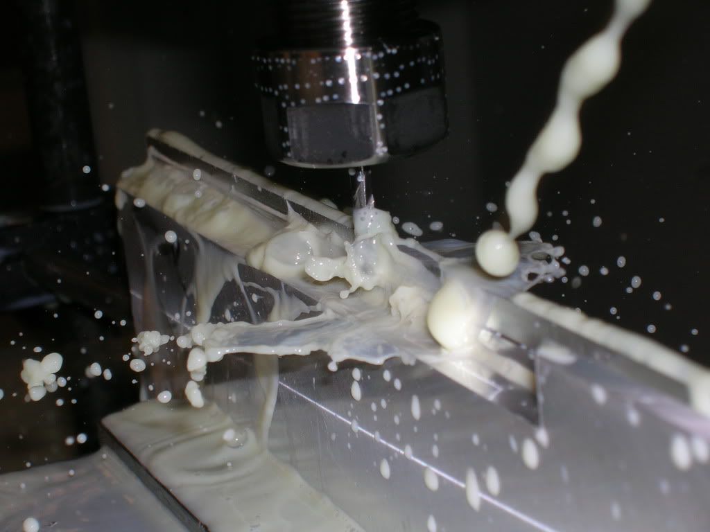
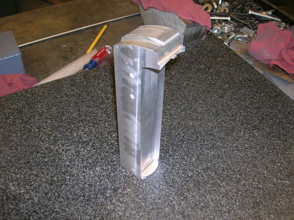
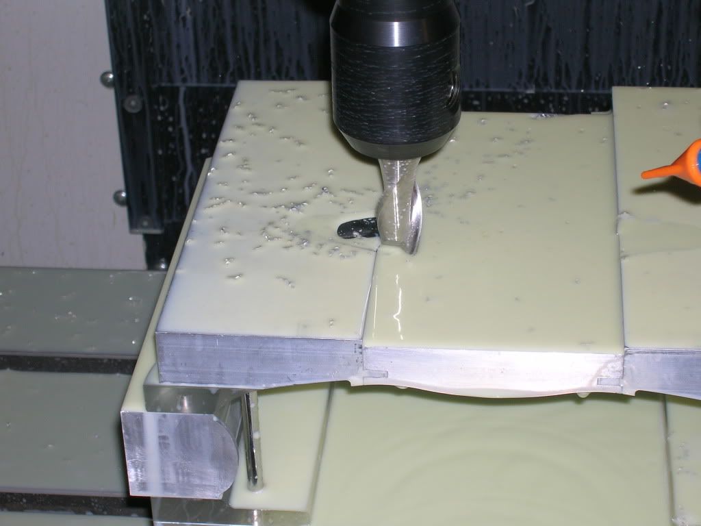
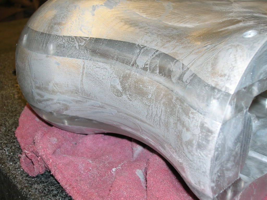
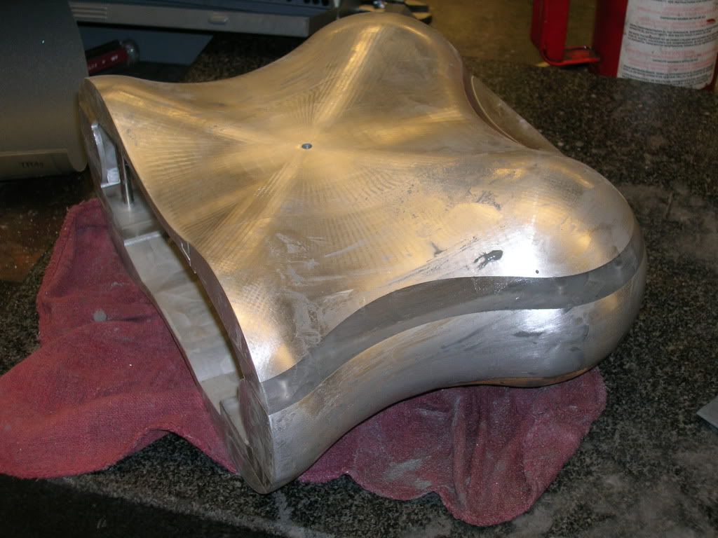
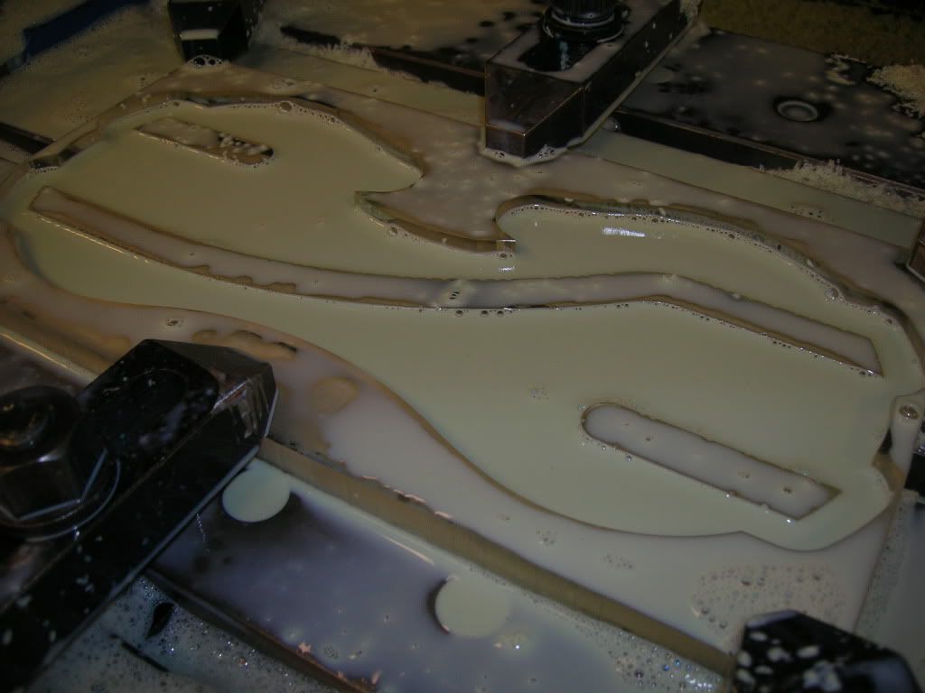
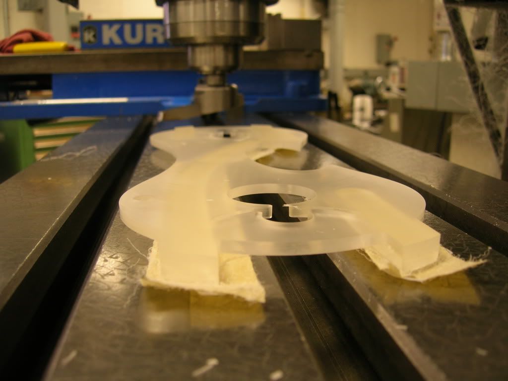
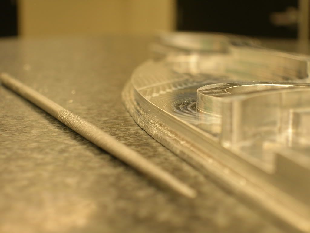
Finished!
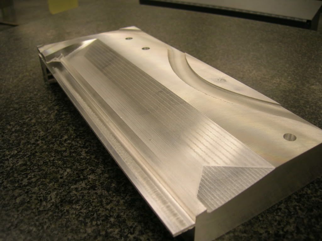
Even if it may not look smooth, I assure you, you can feel no ridges. Just to get a sense of why the process takes so long, I'm using a 1/8" ball end mill making 0.1mm paths. So, for every line the mill takes, it moves over a step of 0.1mm and does the next one. This piece took ~4 hours total in the CNC.
As I'm coming to the end of my career as a full time master's student in the next 4 months, I decided to build an HTPC for the non-existent HDTV that I own
. The plan is to have it finished around the time I graduate (March), or sooner. As I'm sure everyone here knows, it's hard to keep a consistent log as a student, let alone finish a build, but I'll do my best.Specifications:
Currently Bought:
Motherboard: Zotac Geforce 9300-ITX WiFi
Processor: Intel C2D E7400 2.8GHz
Memory: 2GB Kingston DDR2 800
Hard Drive: Western Digital Scorpio Blue 2.5" 80GB
Operating System: Ubuntu 9.10 with XBMC
Future Purchases: (Too poor right now!)
Optical Drive: Slimline Blu-ray Player
CPU Heat Sink: Undecided...It's between the Thermolab Nano, Silverstone NT07, and Zalman VF2000 (due to height restrictions of <45mm).
Purpose:
Since everyone has a different purpose for their HTPC, I figure I'll state mine up front. It won't be storing any media locally, as I have a NAS set up with the goods already. I want an attractive, convienent front end to show my media, stream 1080 content, and the option to occasionally play a Blu-ray right from the computer itself.
I looked up several pre-boxed HTPC's, but none really caught my eye. After this failed reconnaissance mission, I decided to design my own.
Design:
I really have no idea what influenced me on this project. It had to be small. Barely big enough to fit the mini-itx board. It also had to fit all of the components snugly. It also had to look sexy enough for my taste.
Without further ado, here are some drawings. Solidworks was my program of choice, since I've been using it for 5 or so years.
You can see in these drawings I measured everything out and modeled the components so everything can fit nicely. If anyone has any questions as to the logistics of how the case will go together, ask me, and I may have an answer (or I may not know yet :duh
.Quick rendering in Solidworks
Wireframe View - Front
Wireframe View - Side
Wireframe View - Top
Machining:
For the past year or so, I've been working in the machine shop on campus here. I've had machining experience before this, but working here has given me the chance to improve on this. We have a HAAS 3-axis vertical mill, which I adore
waah: no 4-axis). Most of the work will be done on the CNC due to the complex shape that the case takes, since I like things to be oh-so-easy.Also, a note. This won't and can't (with my budget and limited machines) be machined from a solid piece of material. The plan is to divide the case into sections and machine them individually, then connect them together to make the full case. Think of one of those foam Millennium Falcon jigsaw puzzles, only this time it's aluminum :clap:. I plan on machining all of the insides first, lining everything up, then machining the outside all at once.
Frontplate:
The frontplate was the easiest starting point of this whole project. Flat, thin, and not much to it (if I had a nickel...). Unfortunately, I won't have any process pictures for a few sections, since I'm an idiot and kept forgetting the camera. It's simple, however. Take a slab of 3/8" aluminum, cut to size, face with a sick nasty multi-head cutter, take drawing, import to Mastercam, voila!
Here's a snap of the half-completed frontplate. Again, I'm saving the contour for the very last. Mmm shiny.
Wireframe:
Front:
Back:
You'll notice the ends of the piece aren't as smooth as the middle. The clamp in the CNC is only so wide, so the ends tend to chatter a little when the tool goes over those parts. It's still smooth to the touch, but what you're seeing is probably 0.001-0.005" variations. Nothing a little sandpaper can't fix
.The big oval hole is for some IR-visible plexiglass. I don't like anything external, so I hacked apart a MCE receiver and it will be mounted behind this opening. The two holes on the ends are for vandal switches, one for the power switch and the other for the Blu-ray eject (probably). The slot...well the slot is for ejecting the money that I sank into this project :duh:.
Top Chassis Lid:
This piece is a bit more difficult than the last. First, finding a 1" thick piece of aluminum 100mmx200mm is a tedious task. Not to mention that the shape of this piece is...well, complex. As I'm writing this log on a Friday night, the part has been running since 4ish PM today. Projected time to completion, 20ish hours. That may have something to do with the fact that to smooth out the 'scallops' left by the roughing toolpath, I had a small ball end mill (1/8") make very small steps. If anyone doesn't know much about CNCing, feel free to ask and I will do my best to answer. Disclaimer: I am by no means an expert!
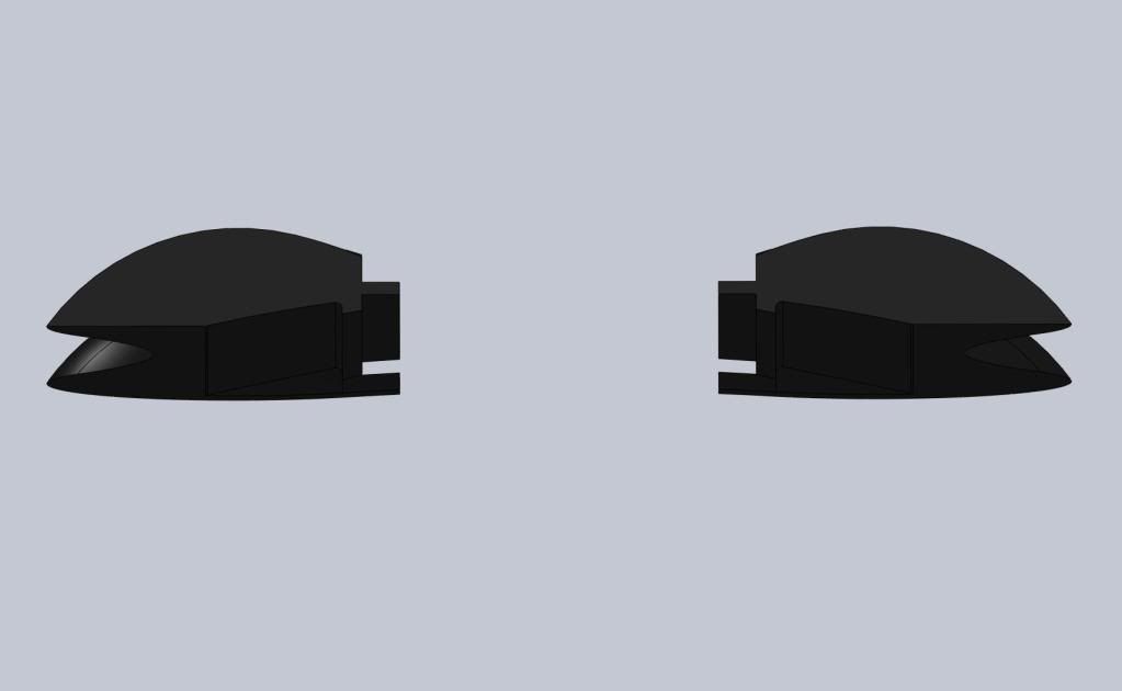
Here's a solid model shot of the piece. I started off by facing each side, then cutting the groove in the sides. Then, the CNC took the spotlight and drilled the holes on the underside of the piece, followed by roughing and finishing.
Solid - Top:
Solid - Bottom
I figured I would provide a picture of the shop I work in, and where this case will (hopefully) come to life. Also, a nice view of the CNC machine is shown.
Machine Shop
Haas CNC
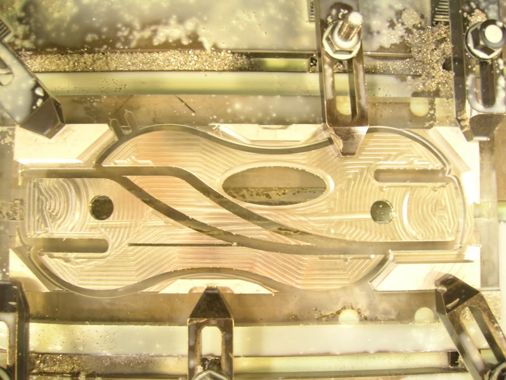
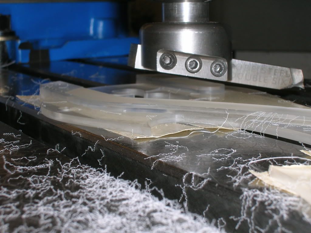
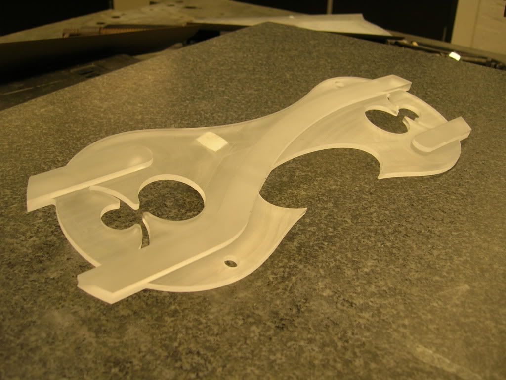
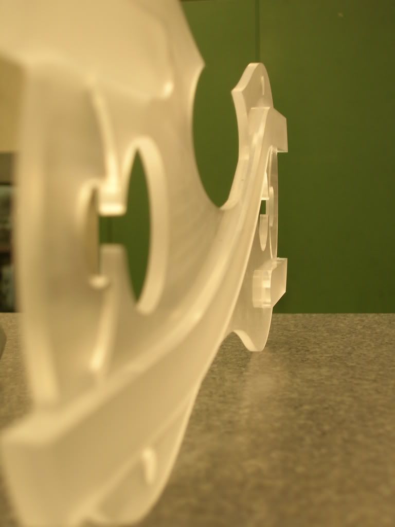
Top Chassis Lid:
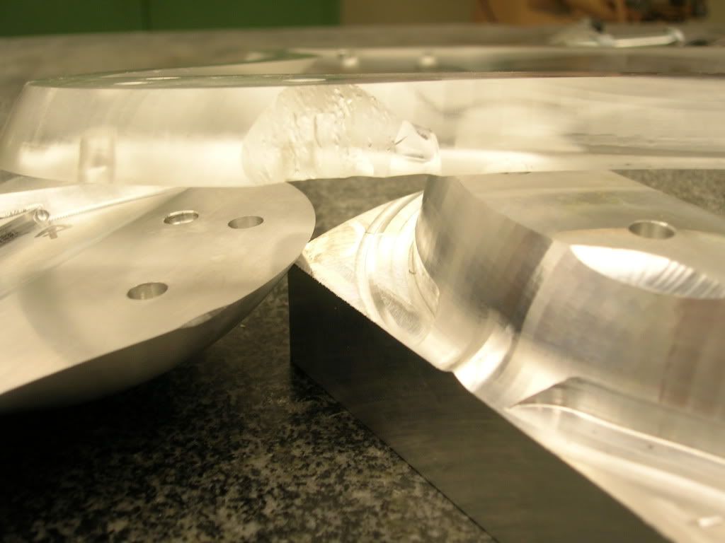
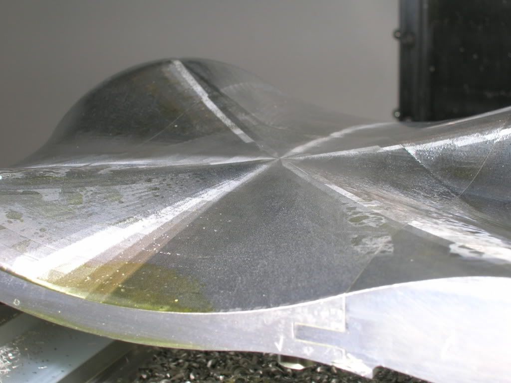
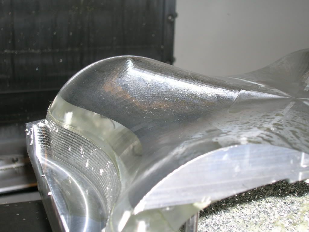
Although I have no progress pictures of this piece, here is the finished bottom of the lid. If you're wondering, this piece took 1.5 hours to rough cut, and ~8 hours to finish.
Finish Pass
Close Up
Another Close Up
Long Shot
Some of you may wonder what the protrusions and holes are for. The long rectangular protrusion is for the hard drive mount, which can (sort of) be seen in the Solidworks drawings in my previous post. The circular and goofy looking shape is for my IR receiver circuit board! The board looks like so:
IR Circuit Board
Top Slices:
Since this case can't be comprised of a single block of aluminum, I chose to separate it into sections. It's basically an inch slice from the top of the case, which results in 2 separate pieces.
Solidworks Top Slices
Solidworks Top Slices
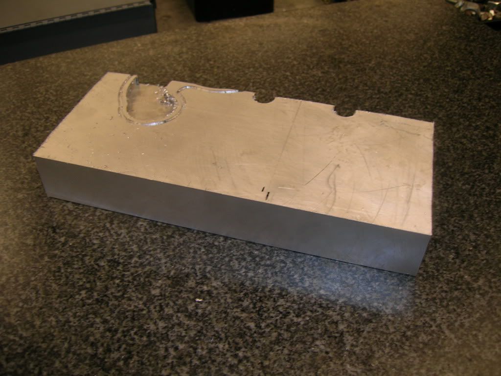
The piece starts out as such...just a simple block of aluminum.
Aluminum Block
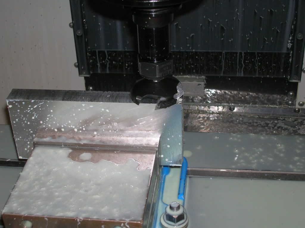
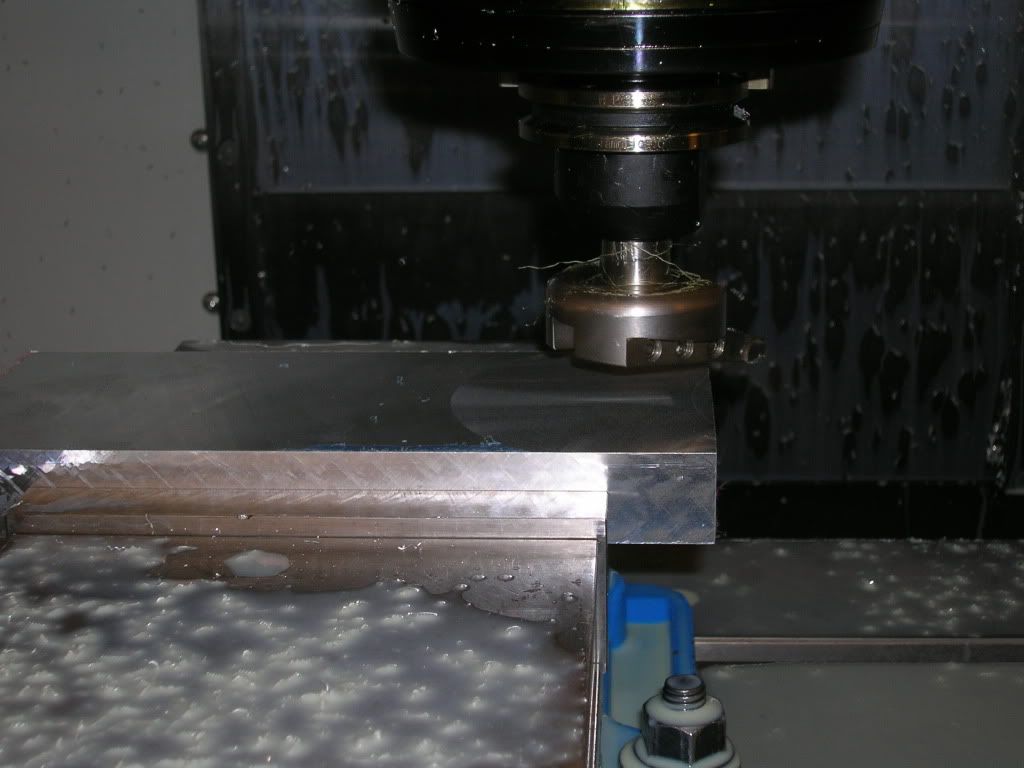
Then, off to facing and edging the piece so everything is level.
Multi-head Cutter
Fly Cutter
End Facing
Then, off to Mastercam!
Mastercam Toolpaths
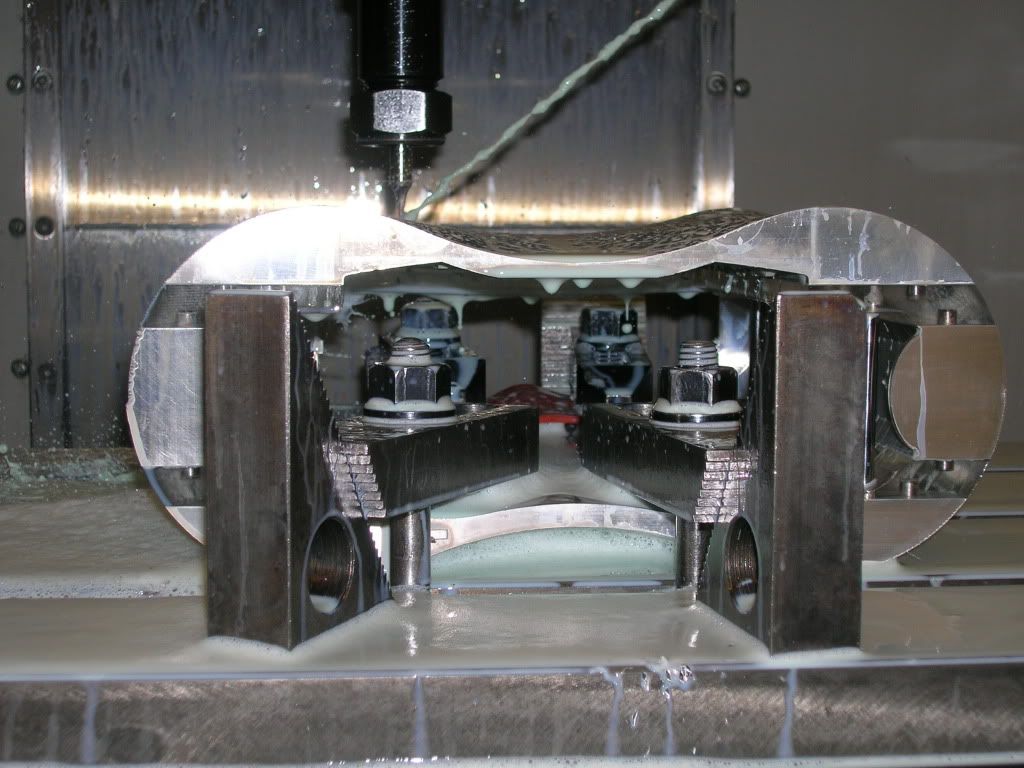
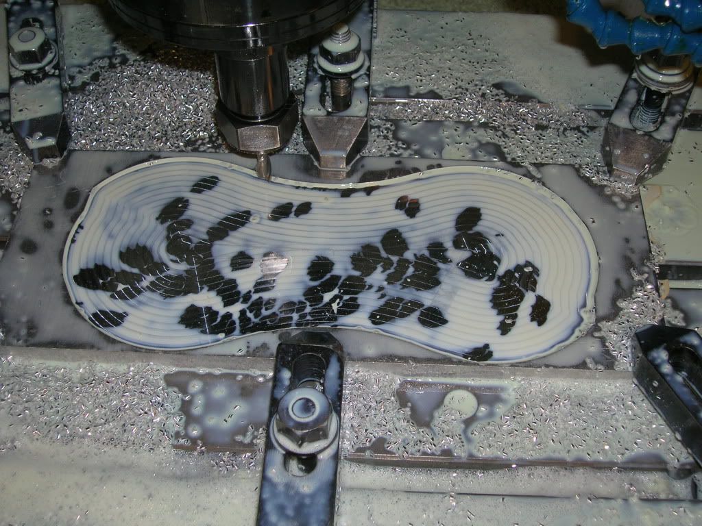
Absolutely nothing visible through the filthy plastic windows and coolant.
Coolant Shot
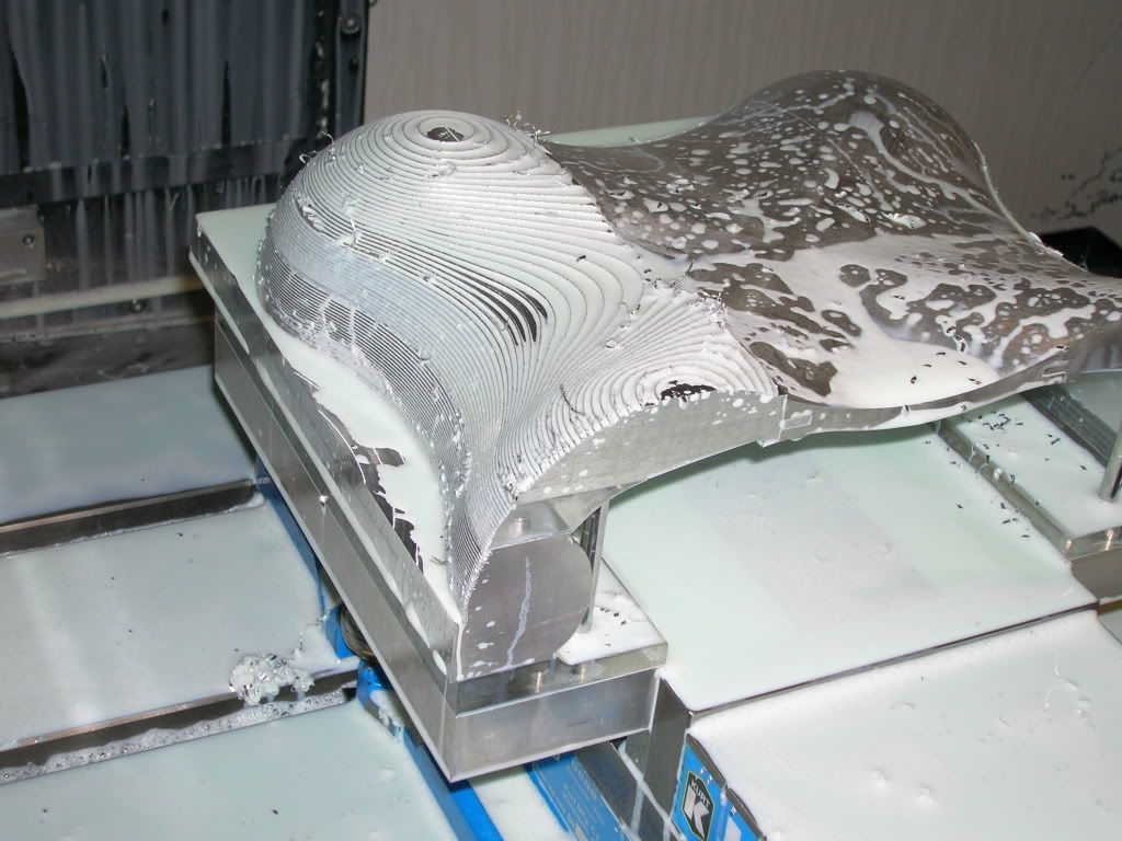
After the roughing paths, this is what is left. Then, we finish it with a smaller ball end mill.
Finished Roughing
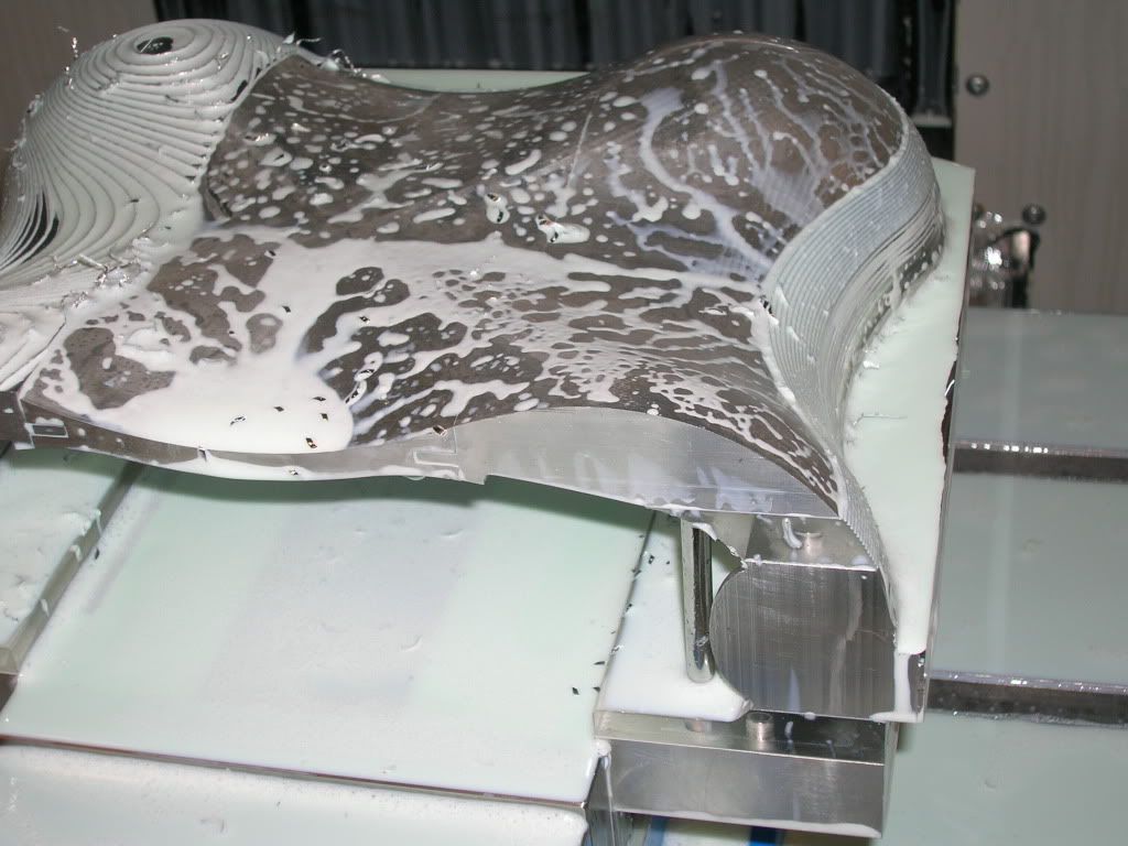
Halfway through the finishing process.
Half Finished
Finished!
Even if it may not look smooth, I assure you, you can feel no ridges. Just to get a sense of why the process takes so long, I'm using a 1/8" ball end mill making 0.1mm paths. So, for every line the mill takes, it moves over a step of 0.1mm and does the next one. This piece took ~4 hours total in the CNC.
Last edited: