Worklog started Friday, April 06, 2007
----+----+----+----+----+----+----+----+----+----+----+----+----+----+----+
2010 REBUILD
This project is being rebuilt starting at post #164
----+----+----+----+----+----+----+----+----+----+----+----+----+----+----+
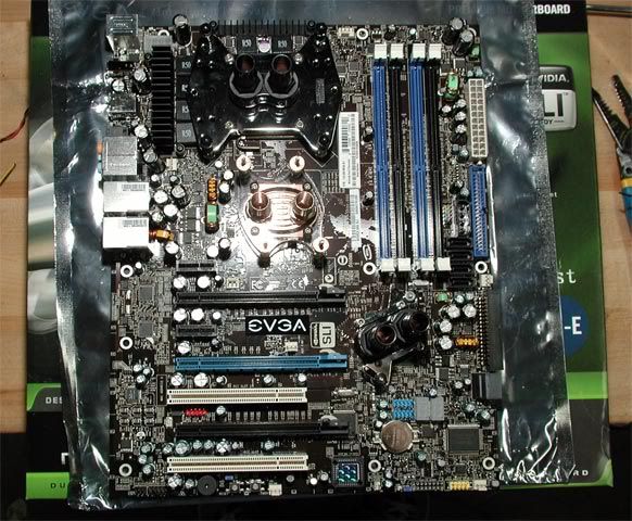
Well, here goes... post #1 at [H] is the start of a new worklog for my new workstation Typhoon. My current workstation Tornado was another project I did in mid 2005, but didn't document. This time, I'll be taking pictures along the way and will post them here. I hope you find it interesting!

Project Criteria:
More to come...
Updates:
10-11-2007: Update parts list
04-26-2010: Update image link
04-30-2010: Start rebuild posts
----+----+----+----+----+----+----+----+----+----+----+----+----+----+----+
2010 REBUILD
This project is being rebuilt starting at post #164
----+----+----+----+----+----+----+----+----+----+----+----+----+----+----+
Well, here goes... post #1 at [H] is the start of a new worklog for my new workstation Typhoon. My current workstation Tornado was another project I did in mid 2005, but didn't document. This time, I'll be taking pictures along the way and will post them here. I hope you find it interesting!
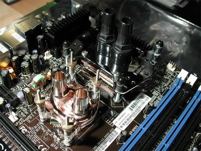
Project Criteria:
- Make it as quiet as possible, with maximum cooling.
- Squeeze in as many hard drives as possible to make one RAID 0 array and one large RAID 5 (or 6) array.
- Maximum hard drive cooling.
- Allow for decent overclock.
- 4GB RAM (probably need to run x64)
- Fit everything inside the case, if possible
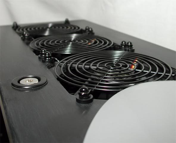
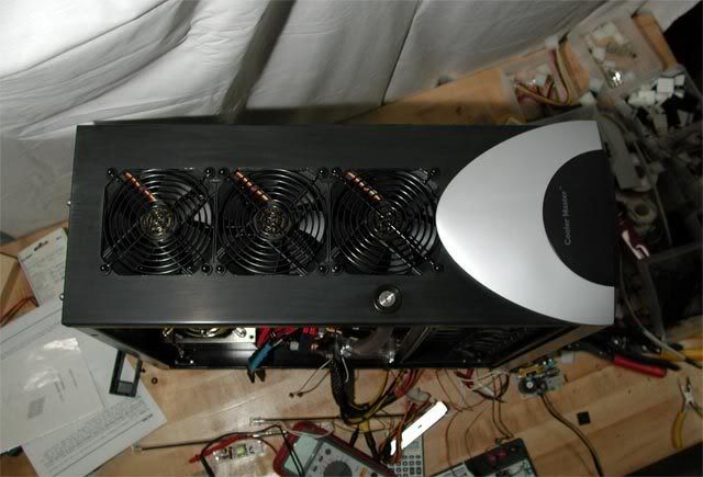
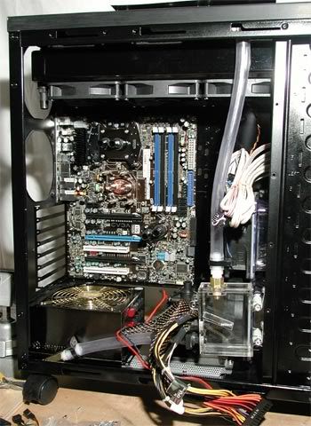
- 1x - COOLER MASTER Stacker 810 RC-810-SKN1, black
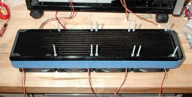
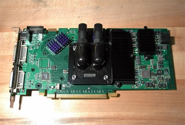
- 1x - Black Ice GTX480
- 7x - Yate Loon 120mm Case Fan - D12SL-12 for GTX480 radiator
- 2x - SUPERMICRO CSE-M35T-1B SATA hard drive enclosure with backplane, black
- 2x - Panaflo FBA12G12U 120mm ultra high speed fan for hard drive enclosures
- 1x - Sunbeam 5-1/4" Rheobus, black (got one from Petra's!)
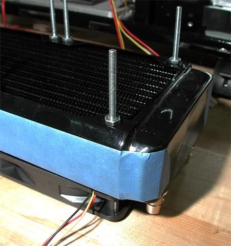
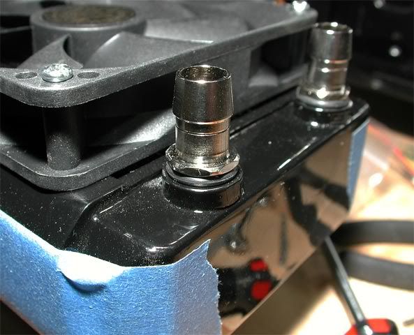
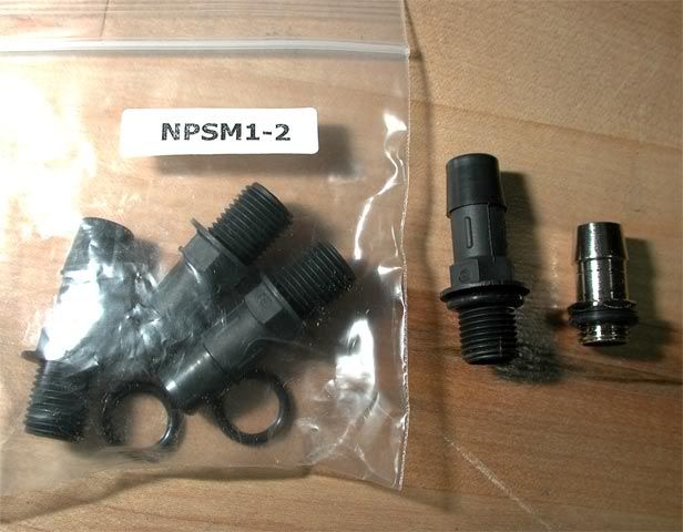
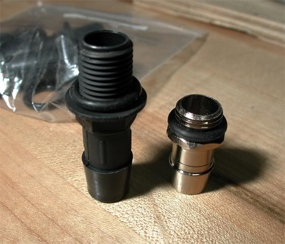
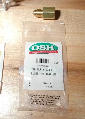
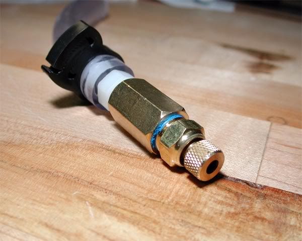
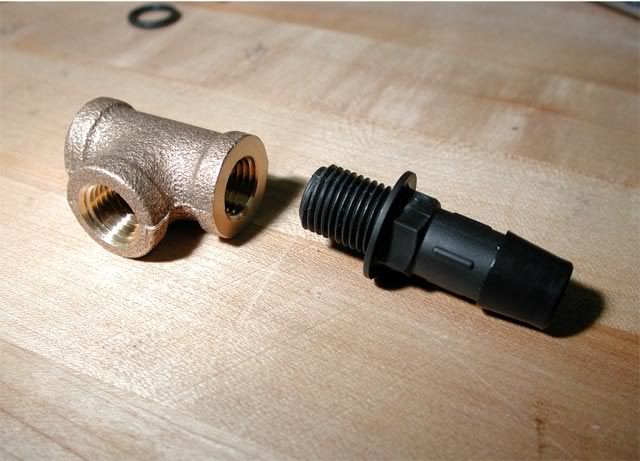
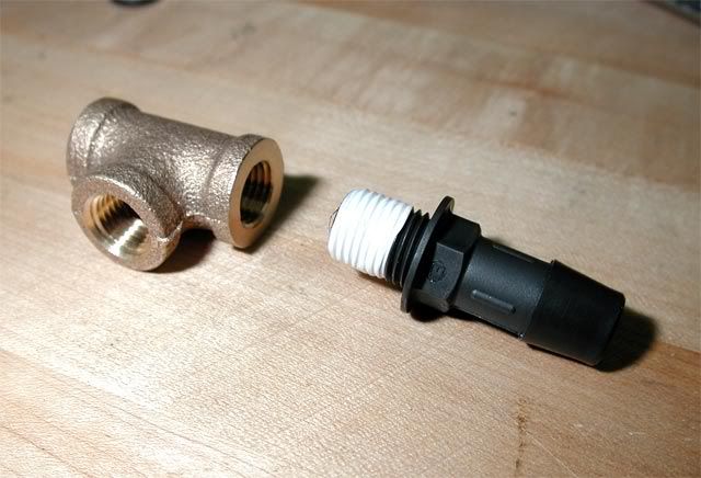
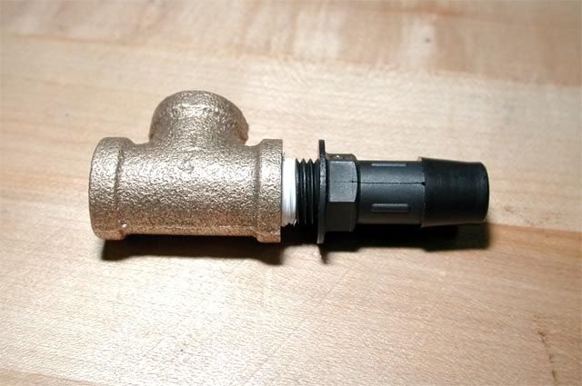
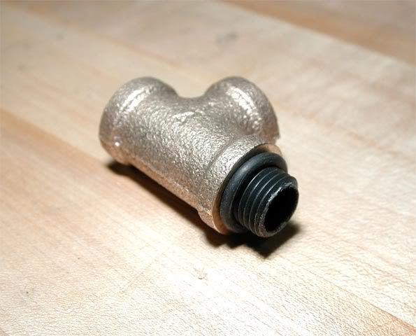
- 2x - 1/4" NPSM, 1/2" OD nylon hose barb, black
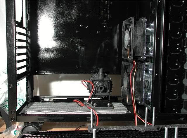
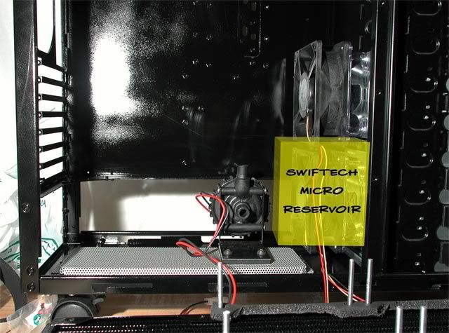
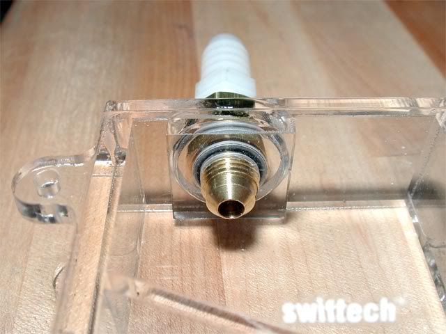
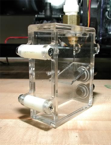
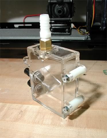
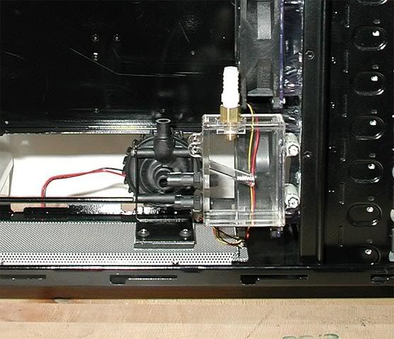
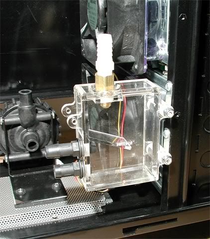
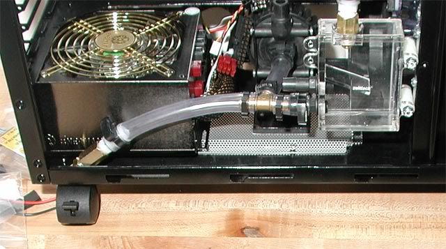
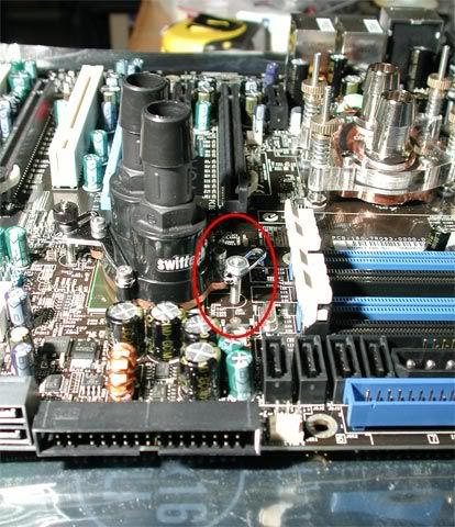
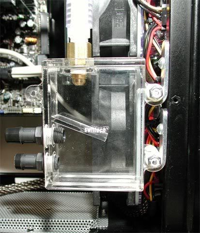
- 1x - Swiftech MCP655 pump
- 1x - Enermax Infiniti 720W PSU
- 10' - Tygon tubing
- 8x - Seagate 320GB (ST3320620NS)
- 2x - 150GB Raptor
- 1x - Areca 1231ML PCI-E RAID card
- ...
More to come...
Updates:
10-11-2007: Update parts list
04-26-2010: Update image link
04-30-2010: Start rebuild posts
Last edited:
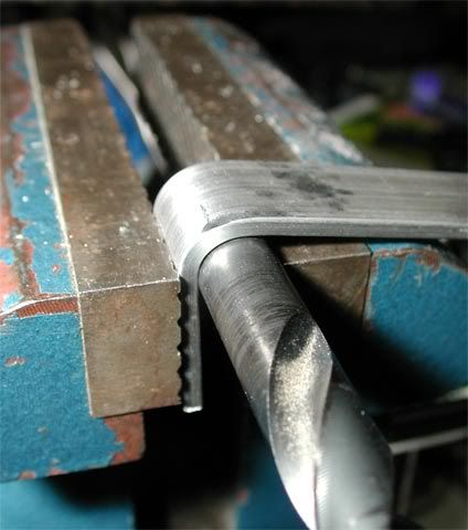
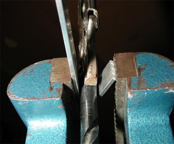
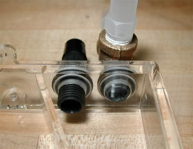
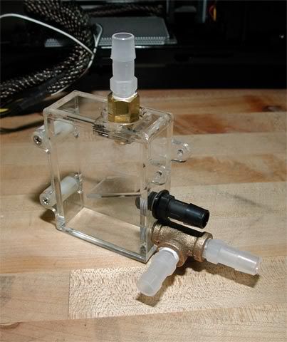
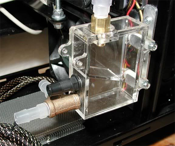
") First, masking tape went down to protect the top during the process. Then, a laser-printed template was glue to the masking tape with spray-on contact adhesive. The template was created in CAD, and for that I always use Pro/E because I happen to be vaguely familiar with it.
First, masking tape went down to protect the top during the process. Then, a laser-printed template was glue to the masking tape with spray-on contact adhesive. The template was created in CAD, and for that I always use Pro/E because I happen to be vaguely familiar with it.