Project: TM-β - a home cluster build

Matrixfy

n00b
Joined
Apr 9, 2017
Messages
41
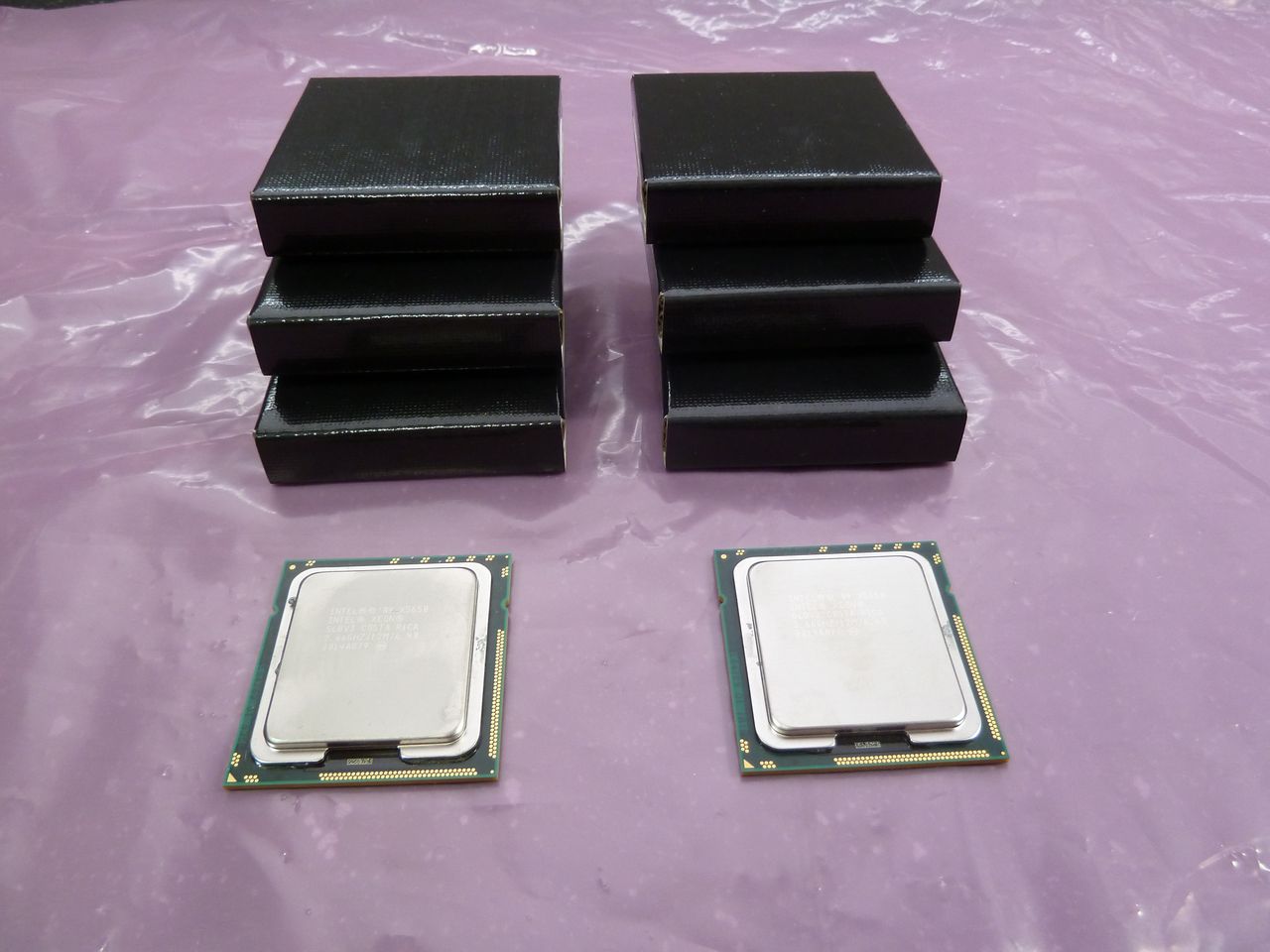
Now that my dual-cpu cube computer is built, I'm free to move on to a new project. Introducing TM-β:
tmb-cpus.jpg


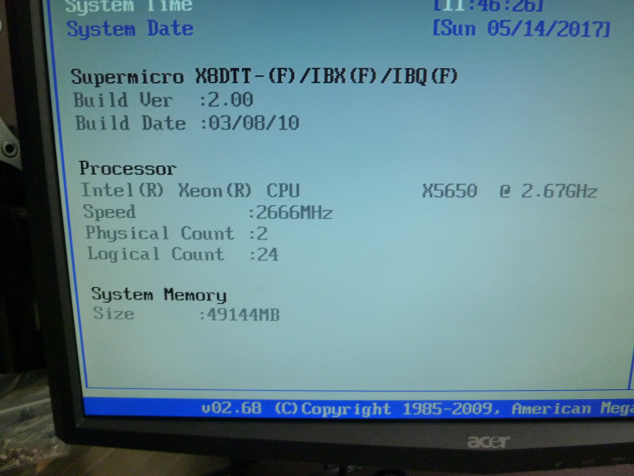
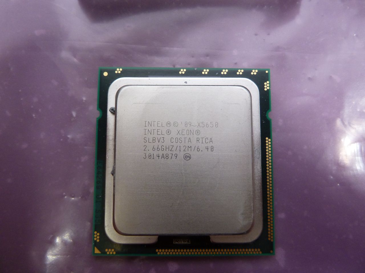
Those are Xeon X5650s - 2.66ghz, 6 core/12 thread, Socket 1366
tmb-cpu2.jpg


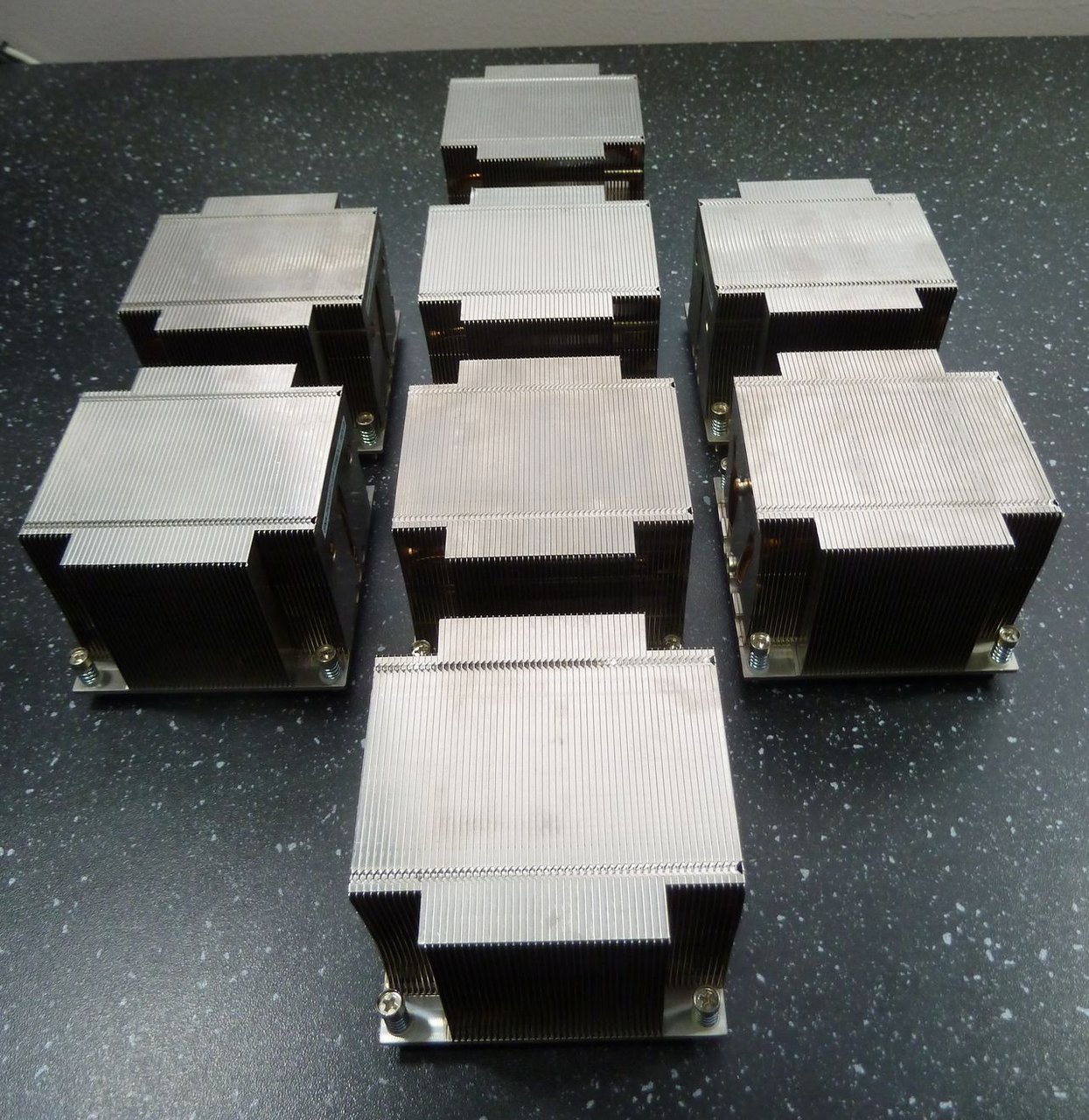
The heatsinks. Supermicro 2U passive, with heatpipes. I was going to go with something bigger, but the boards are... a little special, so I decided not to risk compatibility issues.
tmb-heatsinks.jpg


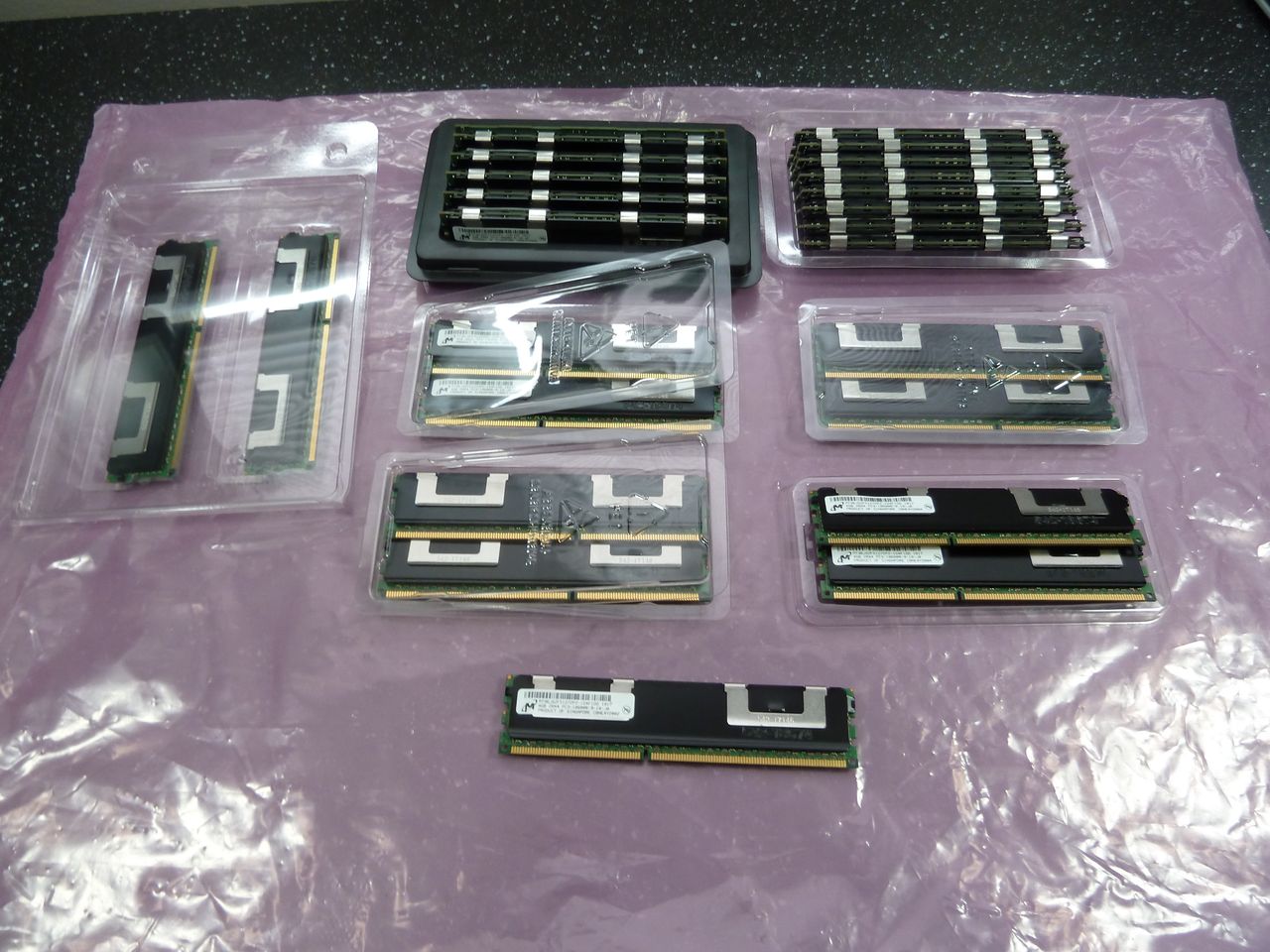
The Ram. 96gb of registered ECC.

tmb-ram.jpg


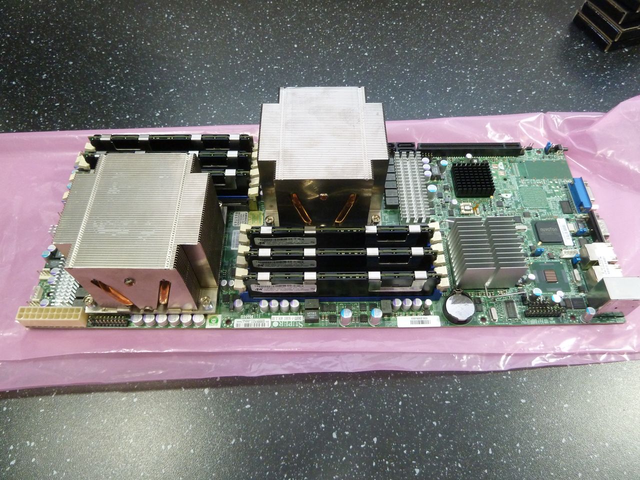
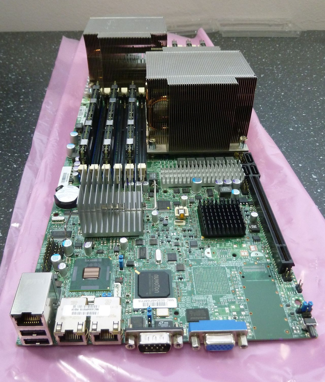
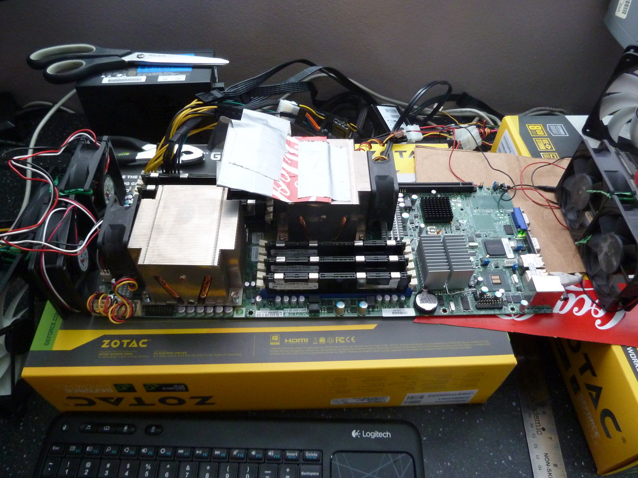
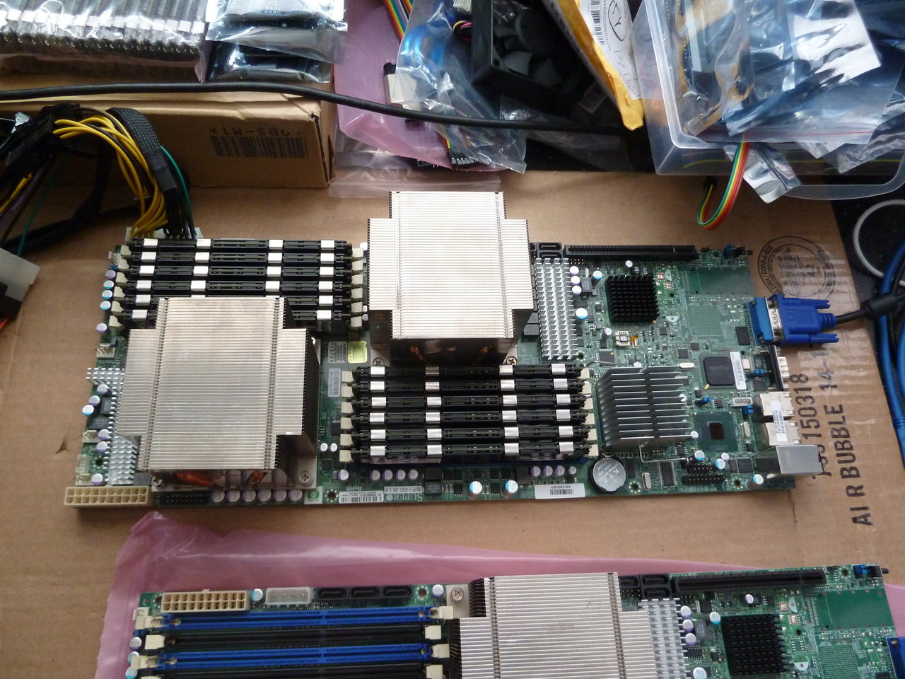
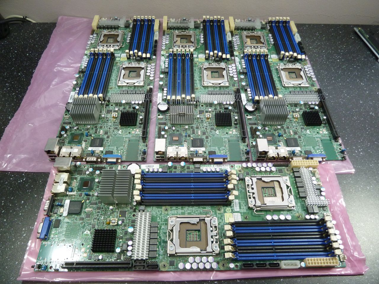
And the boards. Supermicro X8DTT rev 2.
tmb-motherboards.jpg


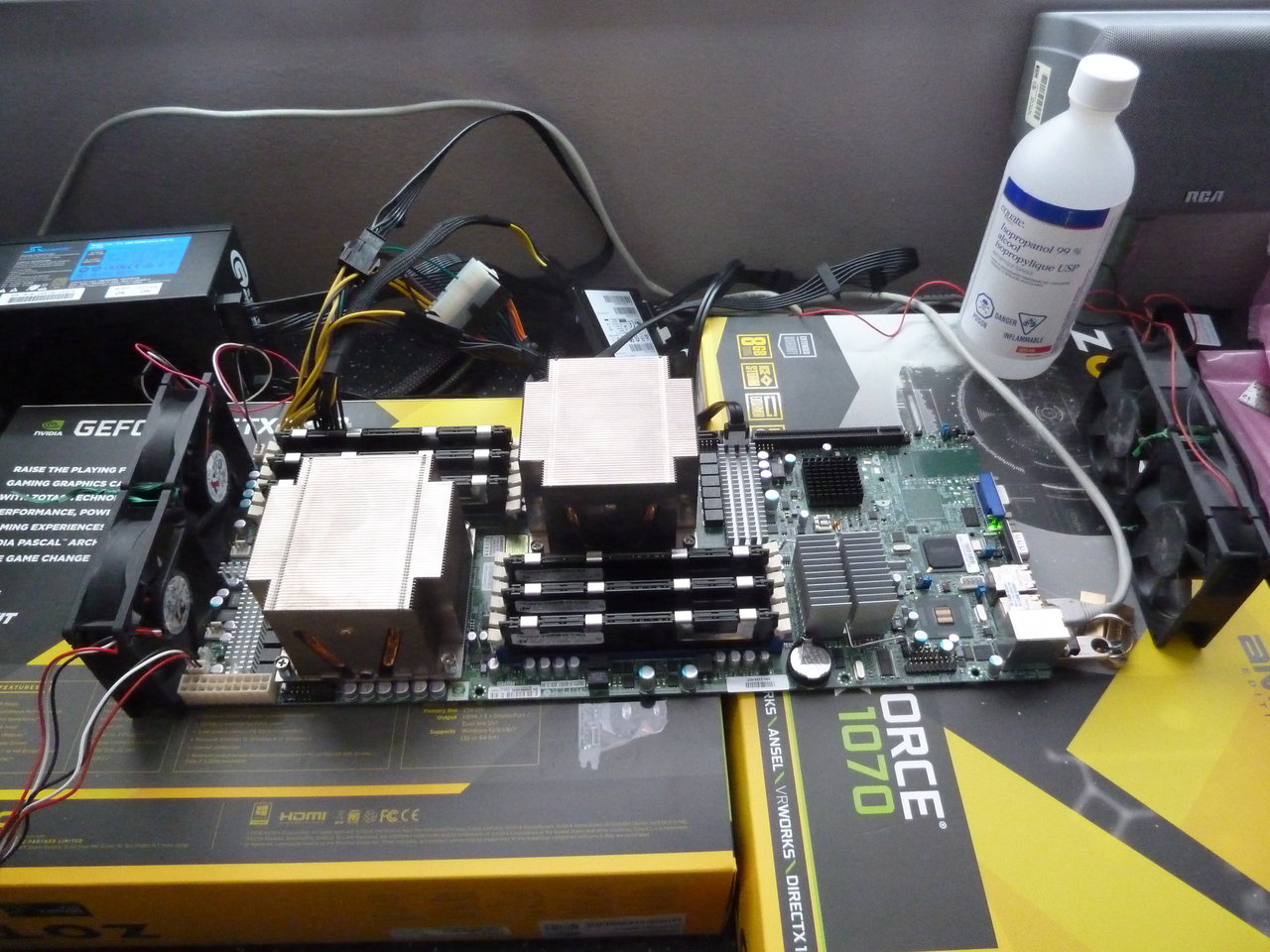
tmb-populated.jpg


tmb-populated2.jpg


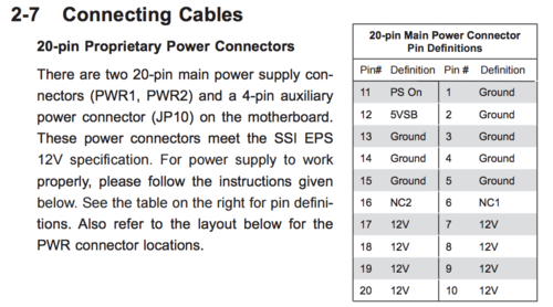
They take a non-standard 20pin power connection, with only 12v, ground, and 5vsb. I have adapters on order, but I'll hack something together for testing for now.

TM-β is for Thinking Machine - Beta, or Beowulf. I wanted to build a small cluster to mess around with - a little rendering here, some distributed computing there. I'm going to be custom building a case for these, inspired by various supercomputers:

A little bit of Thinking Machine's CM-2:
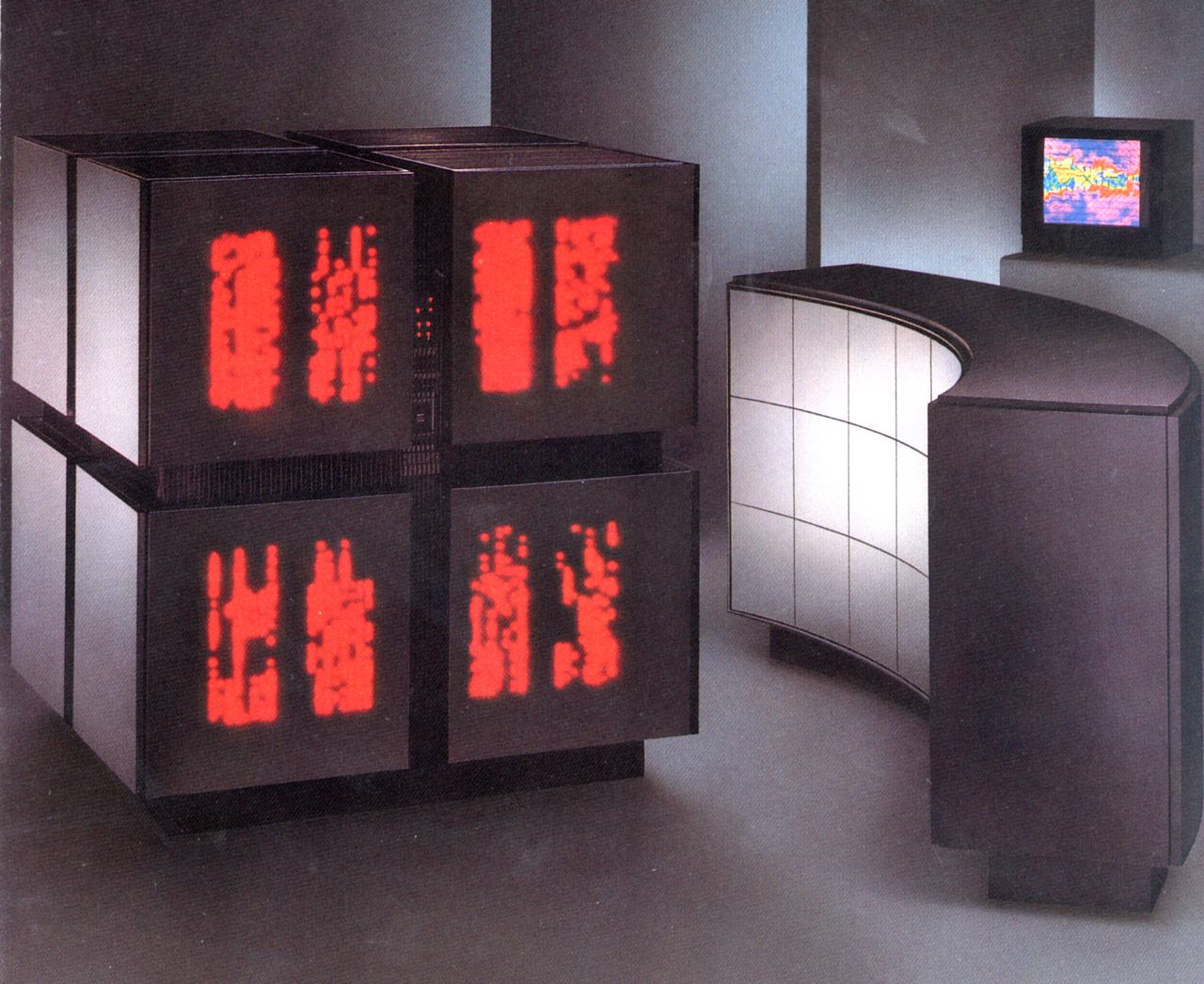
cm2.jpg


A little bit of Thinking Machine's CM-5 (Yes, the Jurassic Park one):
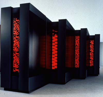
CM5_lg.jpg


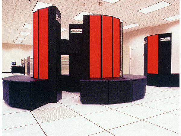
With just a dash of Cray:

102635318-03-01.jpg


I've got a lot of other stuff going on, so I won't be updating often, but I hope someone finds this at least a little entertaining.
 
I recognize that board from your 'Workstation 2017' post. Great to see a build thread for it, should be fun to watch.
 
The first problem to solve is the fact that these motherboards have non-standard 20 pin power connections. They only take 12v and 5v standby, with the rest of the voltages generated on board.

2PgrogB.png


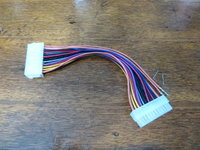
I have adapters ordered from ebay, but they're going to take a month to get here. As I've sourced all my parts from ebay, I have to get the motherboards and CPUs tested ASAP, so I took a stab at making my own.

I have a 4+4 pin extension cable already, so I picked up a 24pin extension cable to get a socket.

I found out they make ATX pin removing tools, but once again I can't get one in a reasonable amount of time, or for a reasonable price. The alternative was apparently to use staples.

So far, so good:

P1010231.JPG

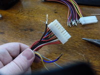
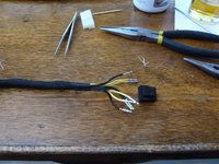
But, after spending nearly 2 hrs working on the thing, I can't get the last few wires out. I moved on to a donor 20 pin power cable instead:

P1010232.JPG

That was much, much easier. Apparently my extension cable is just a piece of junk.

P1010234.JPG

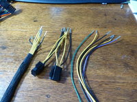
And the 4+4 pin extension was likewise simple:

P1010235.JPG

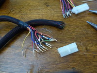
So I went back to the 24 pin cable, and spent another hour or two trying to get the last 2 wires out. Then I got desperate.

P1010236.JPG

I found out that the tabs holding the pins in weren't fully compressible. There was no way to actually get them out without chopping the thing up. Figures...

Then I realize that I'm not quite done. I need 8 12v wires, and the ATX 24pin connector only has 2, plus the 4 from the 4+4 connector. That leaves me two short.

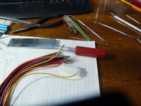
Thankfully, I had a ATX 6pin->8pin adapter laying around, so I pulled that one apart too:

P1010239.JPG

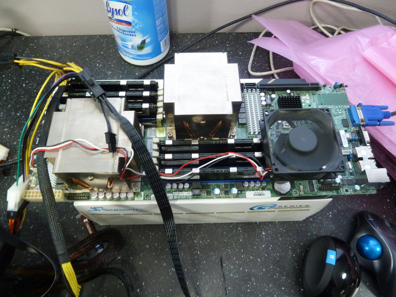
With much finger crossing, I hooked the contraption to the motherboard:

P1010240.JPG


It's alive!

P1010241.JPG


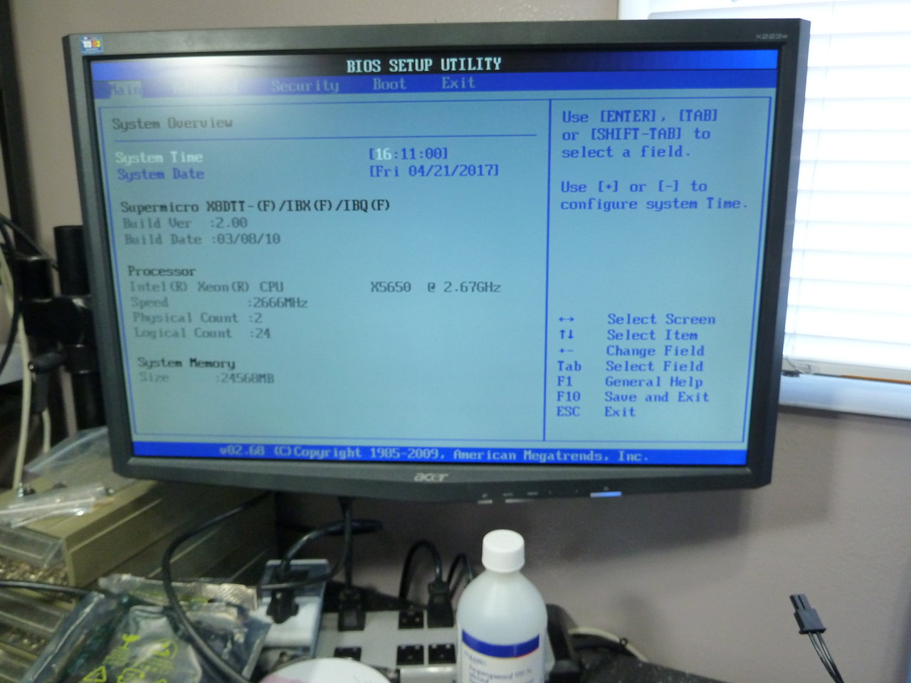
Improbably, all four boards seem to work! Given that I bought the CPUs from two different people, and the motherboards, ram, and heatsinks each from different sellers, I'm shocked that it's gone this well so far.

Next up is trying to design the case itself.
 
Last edited:
Nice work on Frankencable! Good to see it all fired up too.

Thanks :) There was a fair bit of clenching involved when I hit the power for the first time. It didn't help that apparently this board plays dead on a cold start - no heartbeat or power good LED lights, which are otherwise almost always on.
I said that designing the case was the next thing to do, but I wasn't strictly correct. It occurred to me that there's 2 processors with a TDP of ~100w each, the ram (which actually heats up - not something I've noticed before), and another ~30w for the silly Tylersburg northbridge. That's going to be a lot of heat generation in a 6.75" x 3.5" cross section. Checking power draw and thermals definitely has to come next.

Since the power load on this board is pretty unique - 100% 12v in operation - I asked the chaps over at Jonnyguru.com for recommendations, trying to keep the cost reasonable. I knew that power draw on a similar board and gold power supply was around 350w or so, so that meant I could get a good quality but relatively low wattage unit.

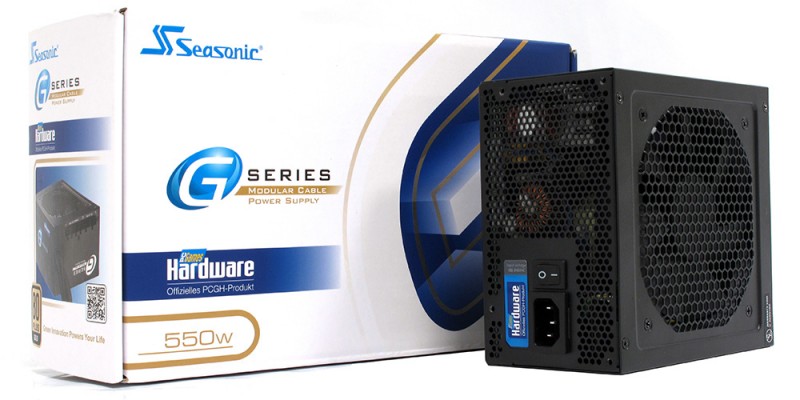
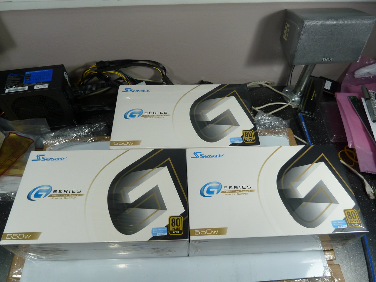
The verdict? Seasonics 550-G series Gold rated DC-DC power supply, yours for a bargain price of only $100/ea!

seasonic.jpg

(Borrowed this pic - can't find the one I took, and I'm too lazy to go dig up the box)


And I need 4. Yikes.

Because it is essentially a 12v power supply and uses DC-DC regulators for 5v and 3.3v, I don't have to worry over cross-loading and minimum load on the other rails.

I bought one to start. No point wasting money if the boards turned out to be duds.

We already know the boards boot. Power draw at the wall, with the gold rated supply, turns out to be bang on 350w. That means I should be able to run all 4 off the same circuit - just.

Thermals have been a bit more challenging. 350w at ~88% efficiency gives about 308w actually being used.

Before getting the boards, in my head I'd imagined a box with a pair of 120mm fans on each end. It turns out the motherboard is quite a bit smaller than expected, and 2x80mm fans fits perfectly across each end.

Something like this:

P1010242.JPG


Air intake is on the left, and exhaust on the right.

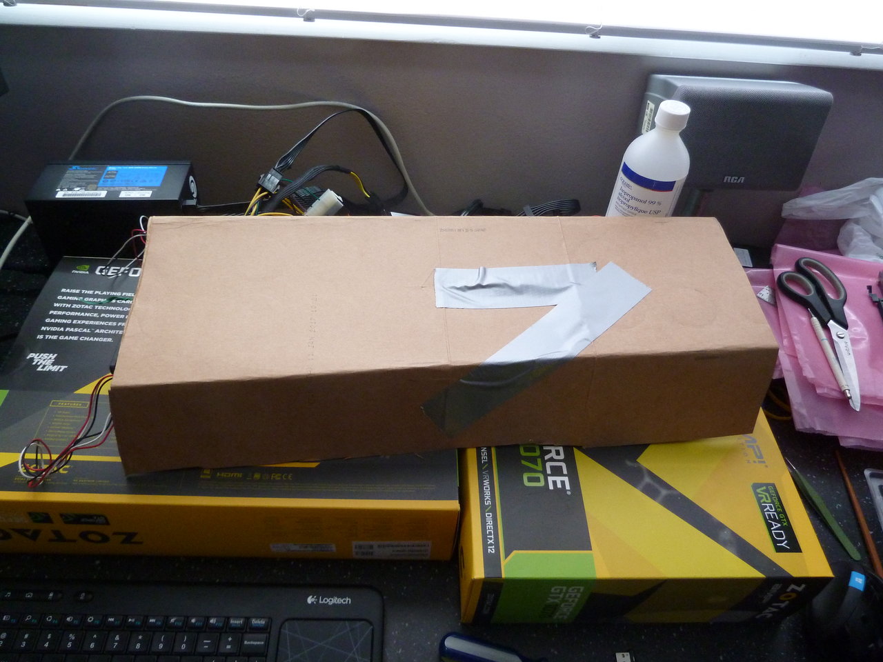
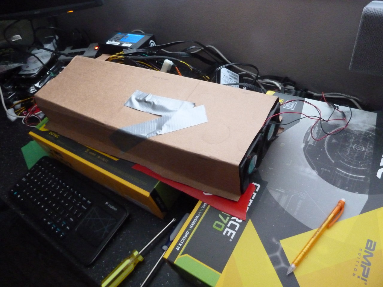
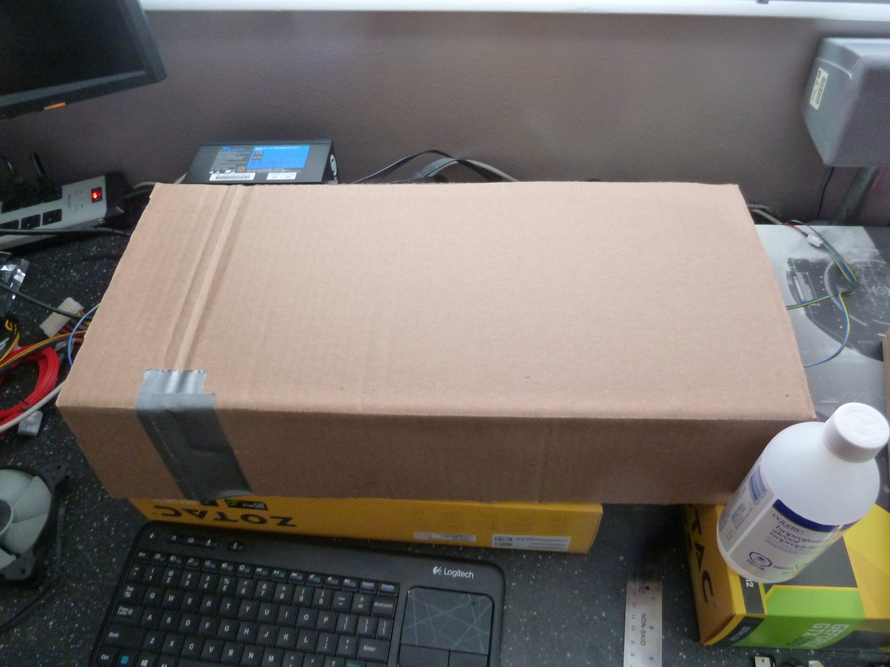
So I mocked up an exterior shroud to see what would happen.

P1010243.JPG


P1010244.JPG


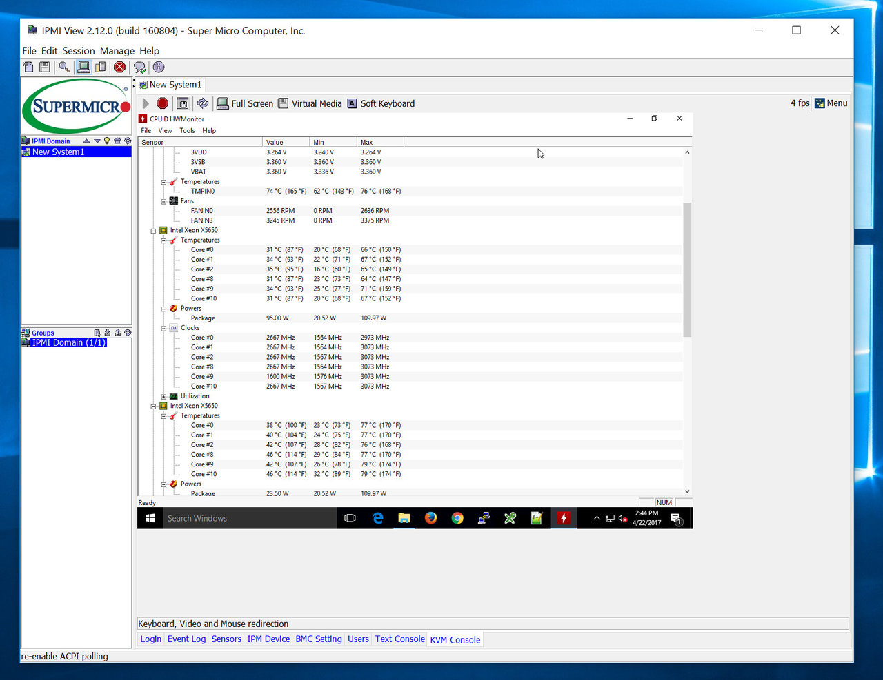
You may notice there's no video cable connected there. There's only an ethernet cable being routed out of the bottom. As this is a server style board, it has IPMI (IP Management Interface?) built in, which gives IP access to everything from the power switch, and sensor data to video output. Among other things, it's a network KVM that even works for the BIOS.

Inexplicably, Supermicro's reporting tools do not show cpu temp. Seemingly it's just a high/low value, so I have to boot into an OS to get actual temps.

ipmi.jpg


I fired up Prime95 and watched the 2nd CPU - the one farthest from the intake at the back - hits 80c or so, and the chipset (gray heatsink on the right) doesn't do much better.

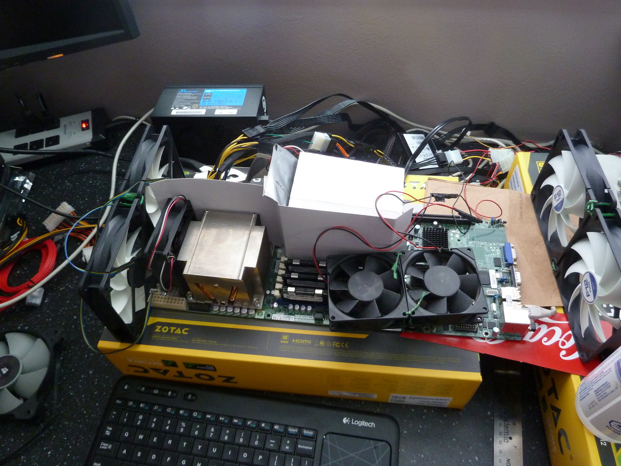
Couldn't get it working very well with 80mm fans, so I tried 120mm. The first setup that provided acceptable (sub-70c) CPU temps looks something like this:

P1010246.JPG

P1010245.JPG


Ridiculous. But it worked.

I decided to go back and try the 80mm fans. I dug up some old 60mm*25mm fans to add to the heatsinks (Does anyone remember the days of Delta Black label screamers? Thankfully I didn't have to resort to those...)

P1010247.JPG


The 60mms aren't attached. I'll have to find some creative way of keeping them in place, but they do sit there perfectly, which is good enough for testing.

And success! Prime95 for an hour didn't get over 65c on the problem CPU, and under 60 for the one on the left. The chipset even stayed under 70c, which isn't terrible either.

So I"m going to need 16 80mm fans, and 8 60mm ones. Here I thought I was done spending money on this project.

Come to think of it, I don't have the removable HD bays or drives yet, either.

And with that success, I'm off to drop another $300 on power supplies...
 
(Does anyone remember the days of Delta Black label screamers? Thankfully I didn't have to resort to those...)

Ahh, the good old days. I still have a few in a box that I just can't get rid of...every couple years I'll run across them and fire one up. Such noisy memories.

Here I thought I was done spending money on this project.

Haha, famous last words. ;)

At least you're not off to spend $2000 on water cooling parts?
 
Ahh, the good old days. I still have a few in a box that I just can't get rid of...every couple years I'll run across them and fire one up. Such noisy memories.


Haha, famous last words. ;)

At least you're not off to spend $2000 on water cooling parts?
Thankfully, no.

Though I just found out that the 4-bay hot swap bay I want will be over $100 too...


Now that I know that my thermal solution should more or less work, the next step is actually design the case. I'm a huge fan of blinkenlights, and the supercomputer in Jurassic Park made a big impression on me as a kid. Ever since, I've wanted to build something just like it but it's been expensive, difficult, and with little ability to make the lights useful in any way.

Now, though, LED arrays can be had cheap from ebay, and driving them with an arduino is relatively easy. Even better, you can actually tie the leds to useful data like cpu load. Even the computers are relatively cheap - Dual CPU, 6c/12t boards for ~$400ca ea. Four of those nets me 48 cores/96 threads at ~3ghz under boost. The stage for my own mini Thinking Machine is set!

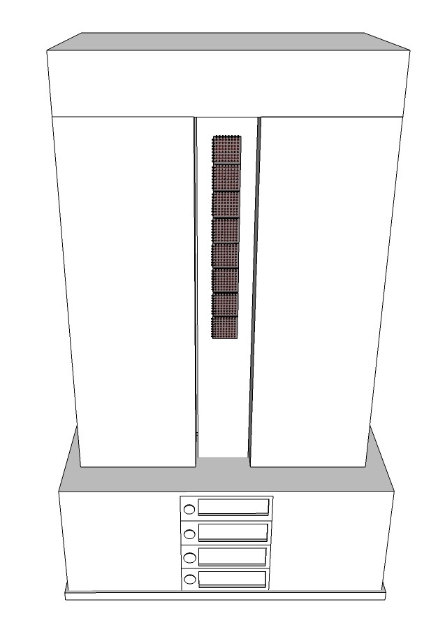
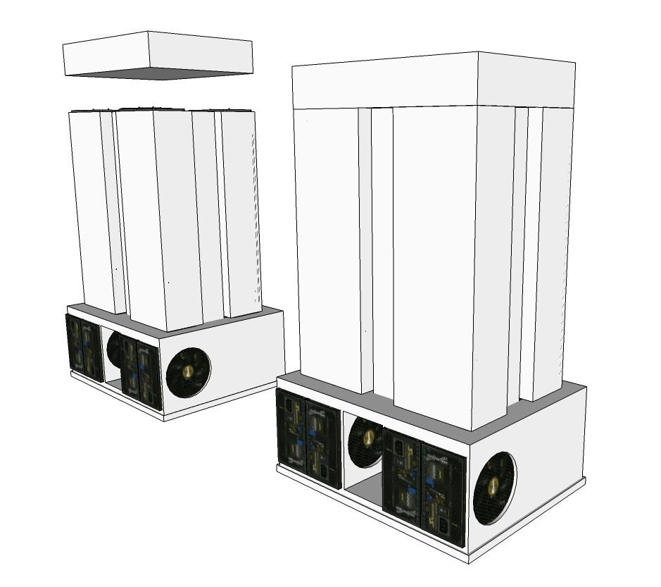
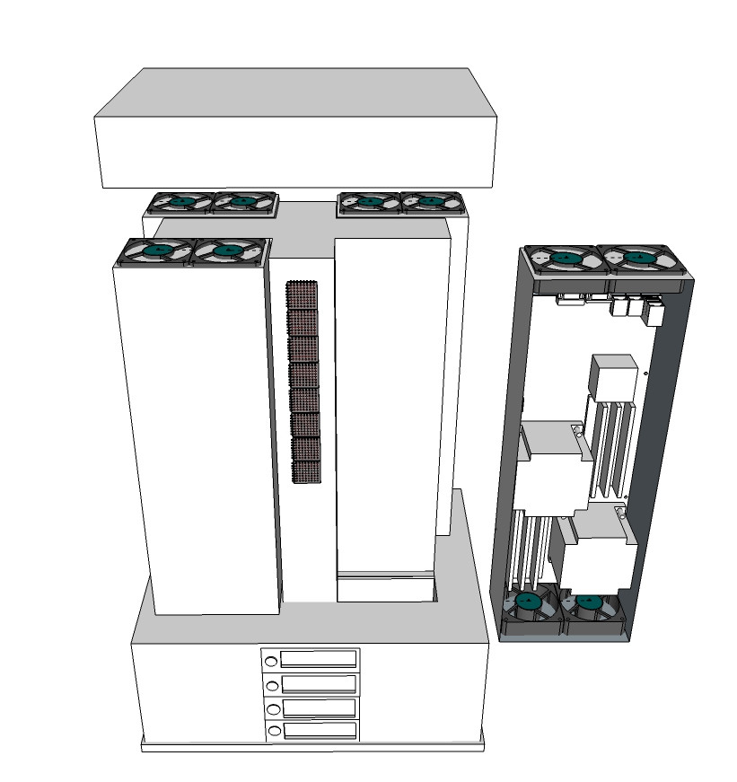
It was the form factor of the boards that convinced me to give it a go. Each motherboard is about 6.75" wide, and 16" or so long - much more interesting than the typical ATX square. I'll be mounting the boards vertically, each in it's own shroud, with intake fans on the bottom, and exhaust at the top.

Tmb-case.jpg


Hard drives go in a 4-bay hot swap bay in the front, along with power supplies and cooling intakes to feed the computing "chimneys". The 4 compute units get arranged in a box pattern on top, somewhat like the CM-2, with the LED blinkenlights (with one 8x8 LED array/cpu) goes in the middle, like the CM-5.

Tmb-case-back.jpg


The top is removable, and is there to cover the fan outlets and the system for securing the compute units to the frame.

Tmb-case-exploded.jpg


That's the plan, so far. I probably won't be posting again for a while, as there's likely to be very little progress over the next few weeks - not only to I have to work out exactly how I'm going to build this thing, but I have to finish turning one side of my garage into a shop to do it in.

This is only a very rough idea of what I want, and is all very much subject to change. The arduino side of things hasn't even been started yet, and I'm still working out what I want for materials and finish. I'll also probably end up ordering things like the fasteners off of eBay, which means an automatic 1-month delay for delivery.

Sorry for the ugly 3d. I'm not fond of Sketchup, but it was most convenient thing for some quick and dirty modelling.
 
Personally I like Sketchup. Your drawings get the idea across.

I like the concept, but I have one concern. Those server heatsinks are some heavy duty hunks of metal. I've seen claims of board warping on consumer mobos and, while the server boards mounting screws are closer together, I still have to wonder about hanging them vertically.

Cheers on the concept, I look forward to seeing how this turns out.
 
Personally I like Sketchup. Your drawings get the idea across.

I find sketchup's controls clunky, and the auto snap seems to be erratic at best.

I like the concept, but I have one concern. Those server heatsinks are some heavy duty hunks of metal. I've seen claims of board warping on consumer mobos and, while the server boards mounting screws are closer together, I still have to wonder about hanging them vertically.

Thankfully, the heatsinks I have are fairly light. All the weight in them that's there is in the base plate, directly on the socket, so there isn't any additional torque on the board. I'm far more comfortable hanging these heatsinks vertically than I am something like those ridiculously over-engineered Noctua monsters.

Cheers on the concept, I look forward to seeing how this turns out.

Thanks!
 
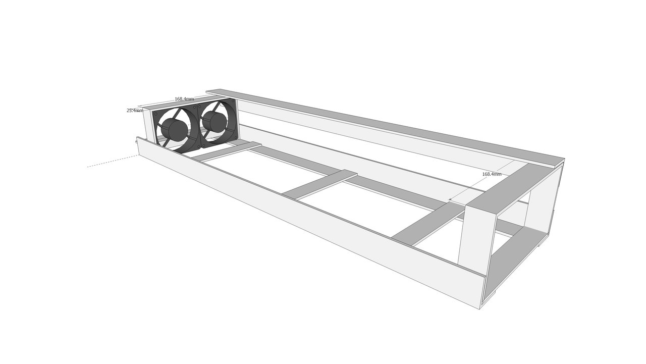
So, I've been trying to design the case/shroud for the individual motherboards, and I was mostly thinking about building a framework out of aluminum bars and angles, then bolting aluminum sheet to that. Sort of like an endo-skeleton. There were issues with this approach - having to countersink bolts to keep from interfering with the next layer up and the like. Not to mention the fact that using tapped holes and bolts to tie multiple layers of metal together would have to be extremely accurate - and sub-mm accuracy across as many joints as I need would be terribly difficult.

Something like this:

endoskelton.jpg


Up until yesterday, that was the plan. Then I found that the cheap and easily available aluminum I was planning to use as the skin was going to be too thin to work well. That meant that I'd have to go with actual 2mm aluminum sheet - more expensive and harder to work with.

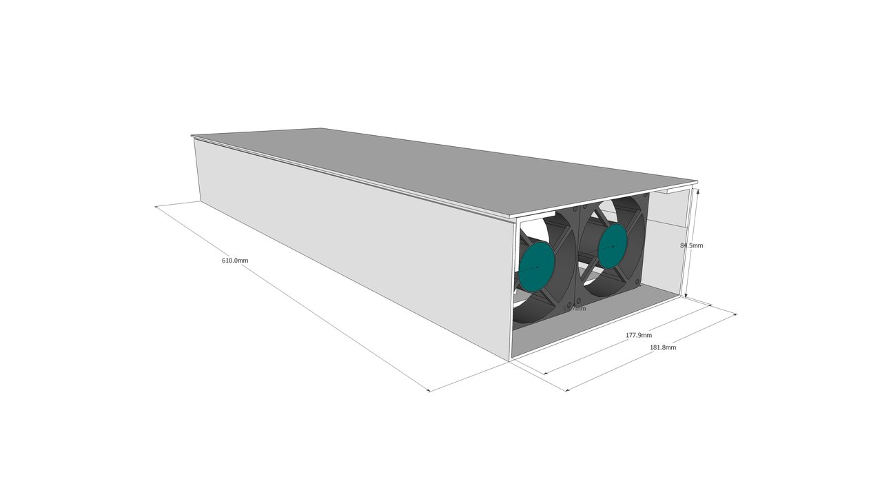
This morning, it occurred to me that if I were using the much stronger 2mm aluminum, I could skip the frame entirely and go with an exoskeleton (or monocoque) approach - build the tray and sides of the case out of a single sheet, and just bolt a lid to that.

Thusly:

exoskeleton.jpg


4 total pieces. Stronger construction. Better motherboard mounting. Easier to mount the fans. All the win.

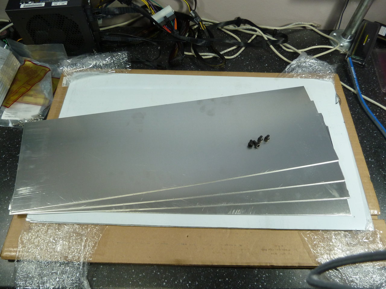
So, I went down to the local Metal Supermarket, and picked up bunch of 2mm 5025-h32 aluminum sheet.

P1010248.JPG


The smaller pieces are the case tops, at 7.5" by 24". The larger pieces are 13 3/4" by 24", and I'll have to hope that the metal brake I bought can handle that. I asked after getting the bending done for me and it was an extra $90 on top of the $90 I spent on the sheet.

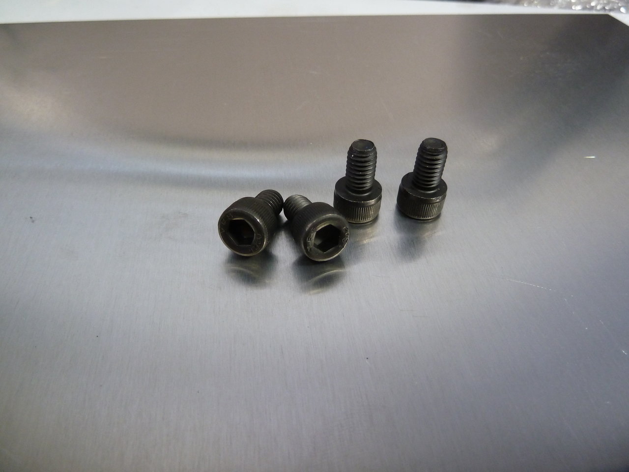
I also stopped by the nuts and bolts shop. I had planned to use M6 Hex Socket bolts to hold everything together, but was afraid it'd be costly. They're about $0.50 each at the local store, and about $0.25 each online - and I'd have to wait at least a month to get them from China.

It turns out the nut and bolt shop sells them for $0.10. I actually laughed when I heard that I could get 50 of them for $5. Keep in mind that I'd just seen them 5 for $2.50 at Home Depot.

P1010249.JPG


Its a good thing they're cheap. This trip was a snap decision, and I'd just intended to check pricing at the stores - I hadn't yet fleshed out the full plan. I ended up under-estimating the number of fasteners I'd need by about 30, and I may be about 1/4" short on the aluminum sheet. Getting more fasteners is easy - I have to go back to both places for more materials for the base framework anyway. The slightly undersized aluminum sheet is a little more difficult, but I can compensate for that without it looking much like a mistake as well.

I also have more parts from Amazon.

Power supplies (the original is in the upper left along with the franken-cable):

P1010250.JPG


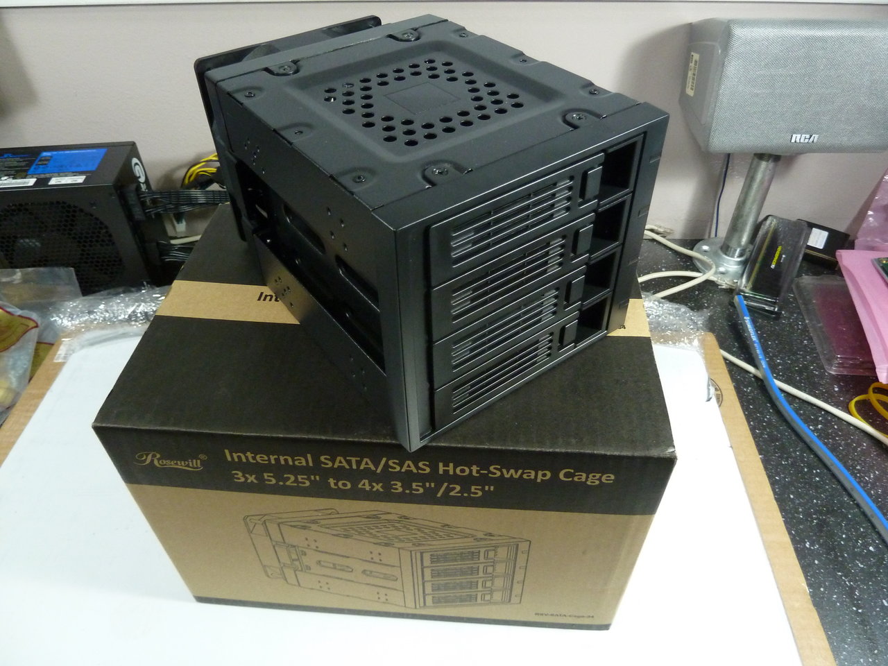
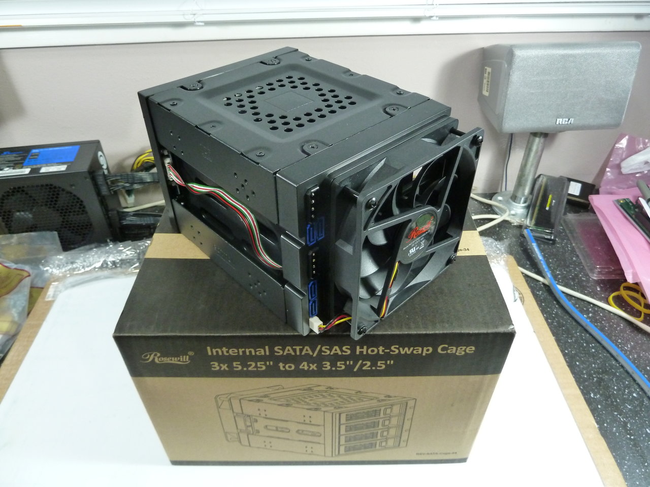
And I found a deal on a 4-bay hot swap drive chassis:

P1010251.JPG


P1010252.JPG


So more progress than expected, sooner than I expected. I'll be bolting the bending brake to my work bench some time in the next few days - hopefully I don't mess up one of my...

*Checks invoice* I don't know how much each sheet of aluminum costs. There's 2 different sizes and they don't break it down. It gives 11.02 as a unit cost for each one regardless of size. That'd be weird and annoying if they were actually the same cost, as one is literally almost twice as wide as the other.

Anyway - I hope I don't mess up one of my apparently $11 pieces experimenting.

Actually. One of the smaller pieces has a bunged up corner. I'll sacrifice it for testing and just buy another one of those. As a bonus, I'll find out what the actual unit cost is as well.
 
Definitely progress sooner than expected, very cool. Pretty good deal on all your experimental bits too. Run back and buy some more big AL sheets before they realize they're the same cost as the small ones. :)

There's not much clearance between the tops of your power supplies and the bottom entrance to the rear towers in your mockup drawing. Do you think you'll get enough air flow? Easy enough to mess around with some scrap and find out I suppose, just something that caught my eye.
 
Definitely progress sooner than expected, very cool. Pretty good deal on all your experimental bits too. Run back and buy some more big AL sheets before they realize they're the same cost as the small ones. :)

They can't quote prices without knowing the dimensions of the metal - the computer calculates everything. Someone said it's all done by weight, which would make the per unit price on the invoice the fault of a lazy programmer.

There's not much clearance between the tops of your power supplies and the bottom entrance to the rear towers in your mockup drawing. Do you think you'll get enough air flow? Easy enough to mess around with some scrap and find out I suppose, just something that caught my eye.

Good catch. I could make it taller, or I may end up making the unit wider and laying the power supplies horizontally - that simplifies contruction of the base considerably, but I didn't like the look as much.
 
So, some progress of a different sort. I tried to set up the bending brake, but I need some bolts and C-clamps to make a go of that, so I put that aside and took a stab at the embedded half of the project - the Blinkenlight array.

The theory is to take some cheap 8x8 LED arrays and run them off an Arduino microcontroller. I'll have to confess, though, that I've never really done anything like this before.

Sure, I've thought about doing it a lot, but I'm a planner, not a doer. That means I have a ton of stuff set aside for that rainy day when I actually get off my ass and decide to do something. I've got a big box of everything from rotary encoders to LCD displays that I've collected over the last few years.

The other impetus to do something was the second of my 2 Xeon Duallies I'd just built. The big one, "Akuma", got set up with a set of Corsair RGB fans. I had always intended the second one, "Tenshi", to have RGB lighting as well, but had been put off by the pricing. Instead, I bought myself a 5m roll of 5v ws2812b LEDs and put them aside till I, once again, got off my ass and did something.

As it turns out, the Tenshi build was more or less complete, and I wanted to install it in it's final location. That location is a little awkward to get at, so if I wanted to light it, I'd have to do it sooner rather than later.

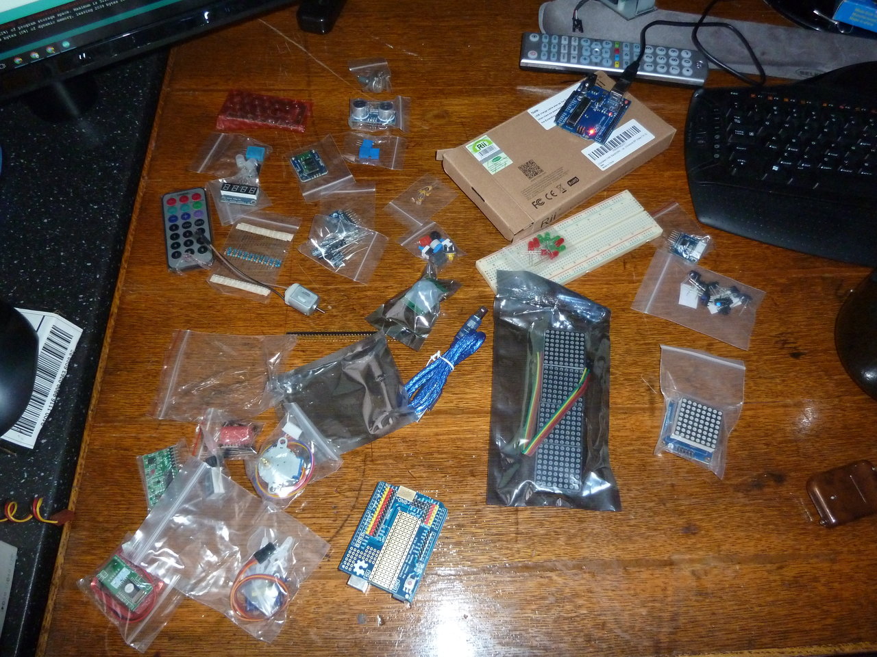
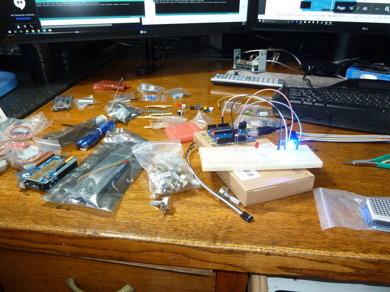
So, I dusted it off and pulled out my arduino learning kit.

P1010281.JPG


I went through the first few projects in an hour or too, making LEDs blink.

P1010282.JPG


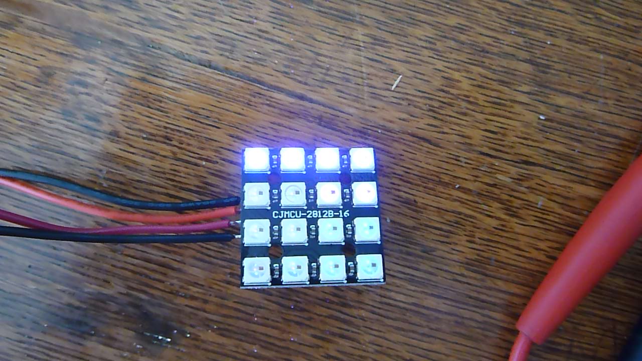
After messing about with the single LEDs, I jumped straight in to the FastLED library for RGB leds.

P1010283.JPG


Success!


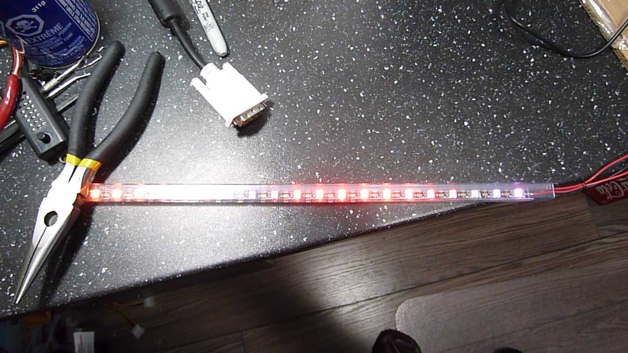
From there, It was a pretty short step to go from the 16 LED test board to an actual LED strip.

P1010288.JPG


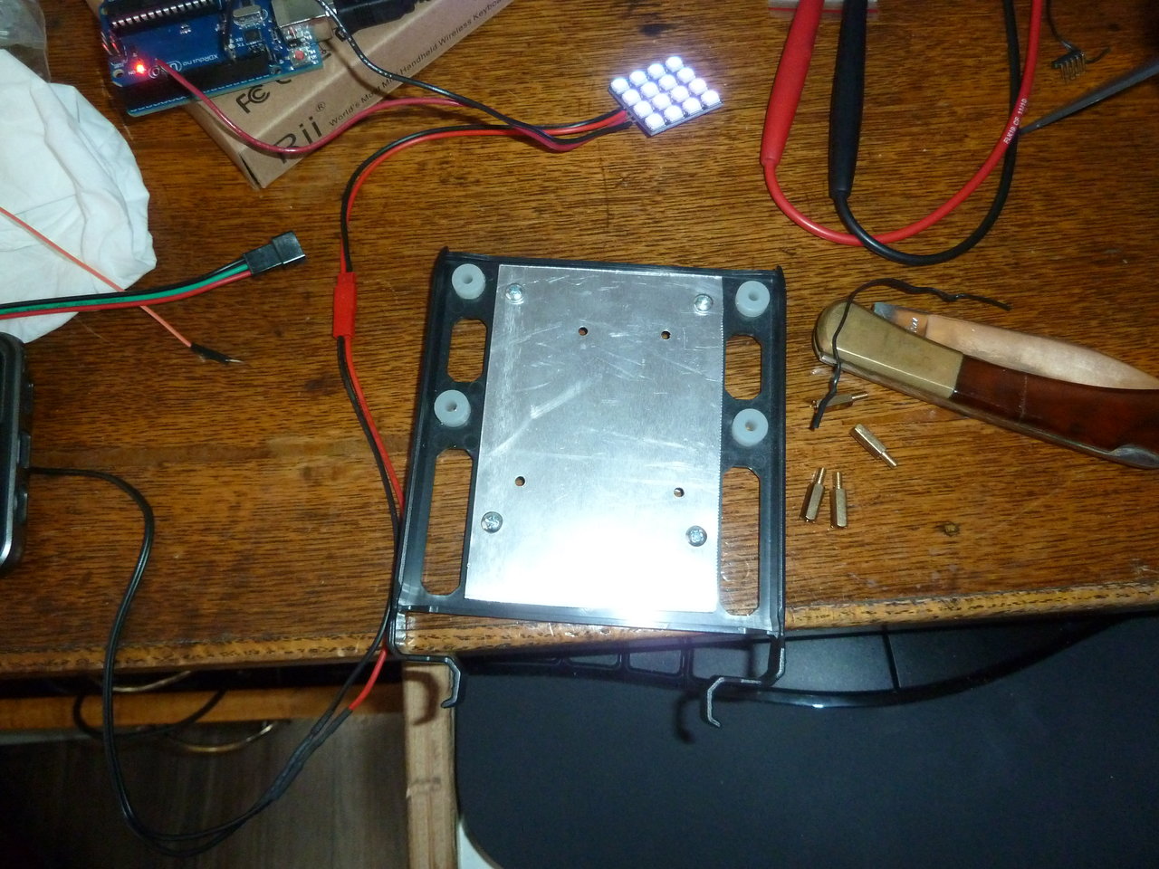
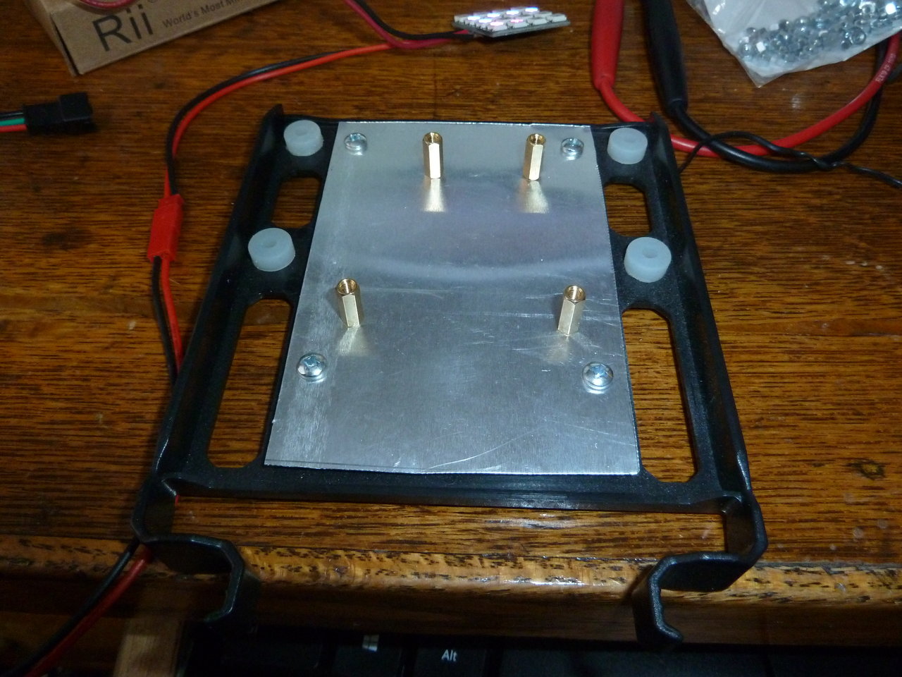
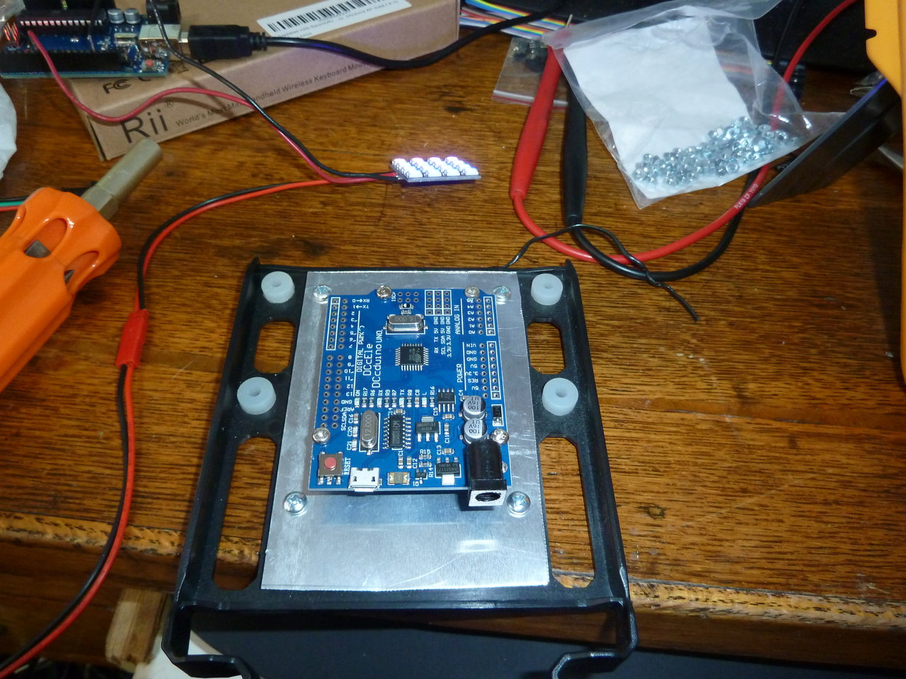
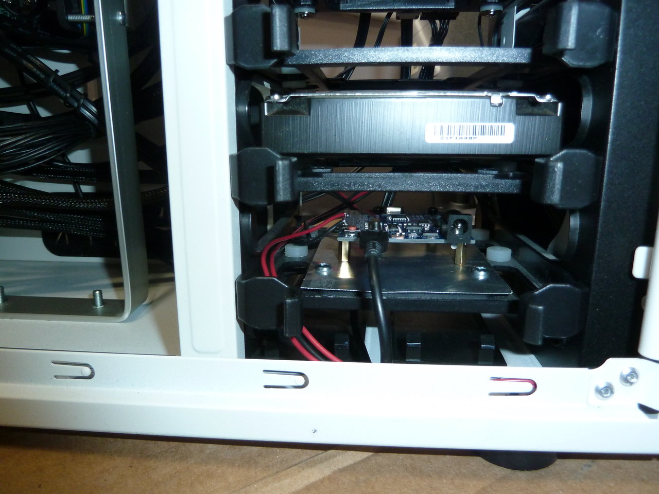
From there, I hacked together a mount for the Arduino on one of the HD trays on the Antec P280.

P1010284.JPG


P1010285.JPG


P1010286.JPG


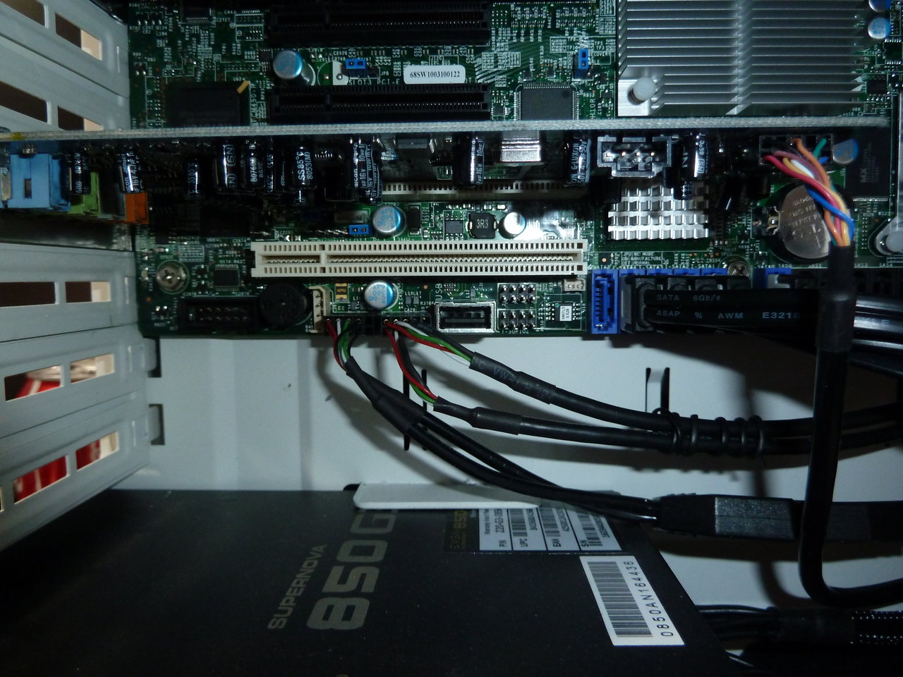
The Arduino itself is powered off of USB. I'm going to use this setup as a dev platform to allow software control of the LEDs. The motherboard, being a Supermicro Server board, actually has a full USB2.0 port directly on the motherboard itself, so I don't have to use a header.

P1010289.JPG


P1010287.JPG


The fruits of my endeavors


It's just running a test sequence for now, but at least the HW is finished and installed for the next time I get the urge to do some dabbling.
 
Last edited:
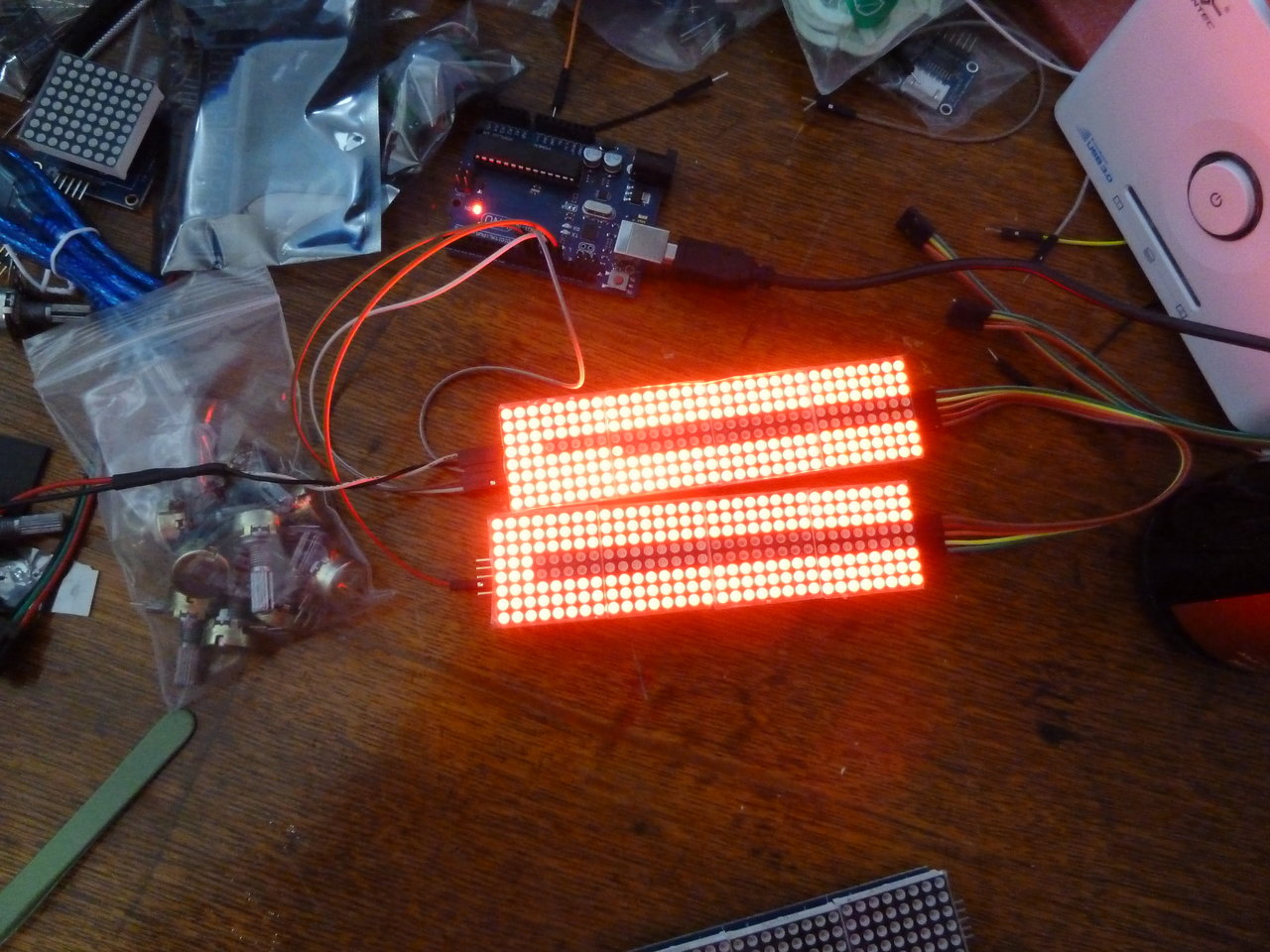
Once I'd gotten the warmup out of the way, I tried to tackle the next bit of the cluster project - the Connection Machine-style LED display. This is an array of red LEDs indicating CPU load on the front of machines from Thinking Machines CM-1 and CM-5 supercomputers.

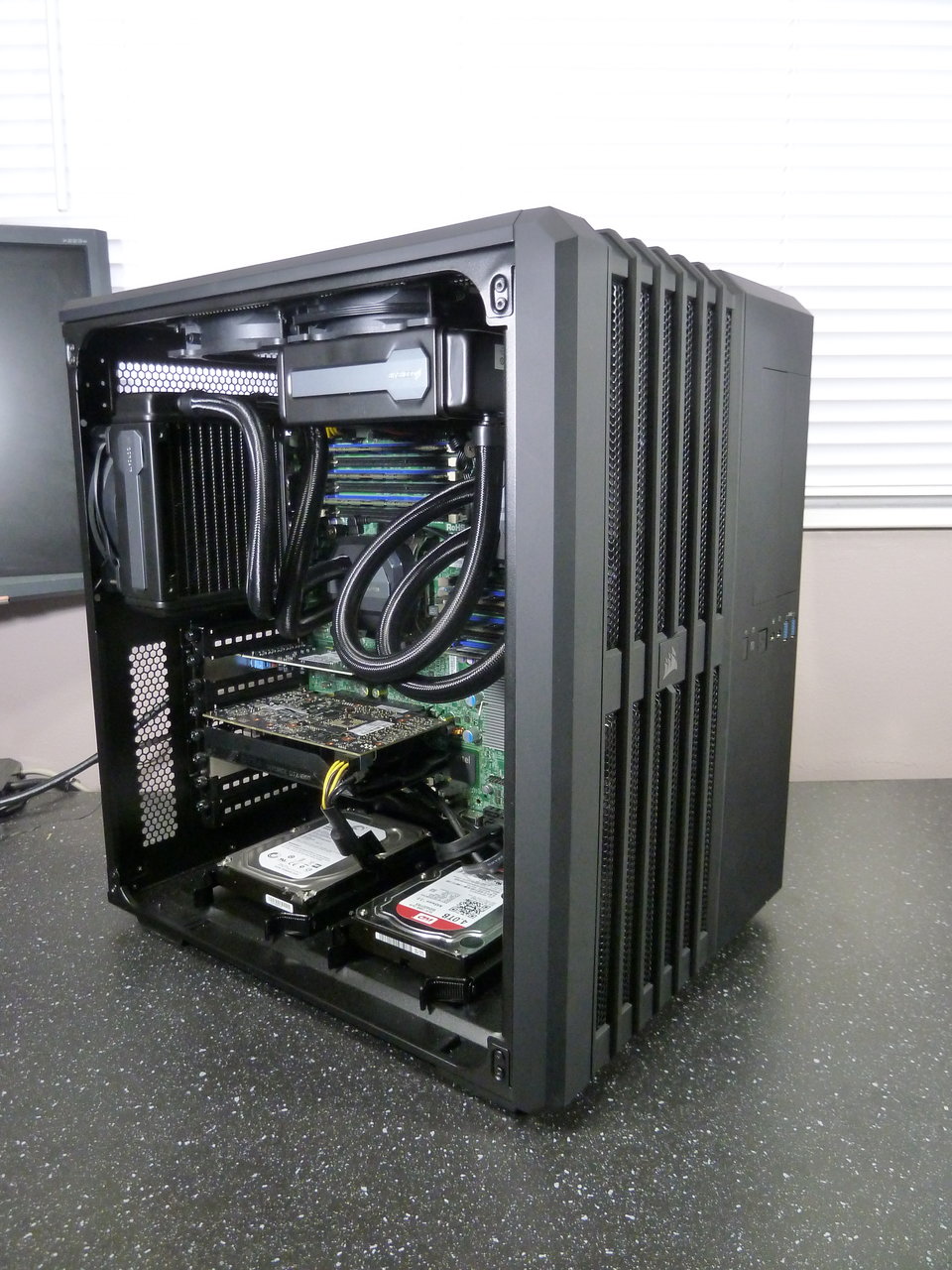
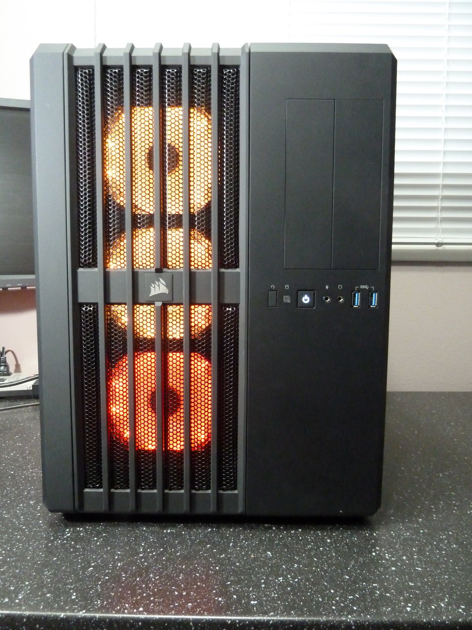
I had originally planned this for use with "Akuma", mounting two blocks of 4 8x8 LED panels - one each in the vertical 5 1/4" drive bays on the Corsair Air 540 case.

For those that haven't seen my posting in the dually or workstation threads, here's Akuma - the drive bays are on the right:

P1010195.JPG


P1010178.JPG


It was during the planning of that build that I came across the X8DTT motherboards, which had an unusual form factor that I hadn't seen before. To the detriment of my wallet, I came up with the idea to combine those motherboards and my LED array plan and this project was born.

Unfortunately, the LED arrays are a lot harder to work with than the LED strips. I couldn't find much good documentation on the hardware setup - most everyone I saw looked like they just plugged the things together and made them work.

It took a couple of days to get one block working, but there'd be glitches - one 8x8 block might partially light, or drop out completely for a while. I couldn't run them for more than 10min or so without something going wrong.

I checked and double checked the wiring, and tried 3 different power supplies. I though I'd nailed it when running the LEDs off the Seasonic PC power supply seemed to fix the issues, but everything fell apart when I tried to daisy-chain a second block of 4 arrays.

It turns out that not only did I have insufficiently stable power, but trying to use the hardware-based serial pins on the arduino cause issues without wiring a common ground between the USB powered arduino, and the externally powered LEDs. Something nobody bothered to mention. (I had seen it recommended for the RGB LED strip, and I'd initially set the arrays up that way, but my first power supplies were causing issues).

So several days, 3 power supplies, and two different control libraries later, I mostly got it to work, but only for a single test cycle. After one particular test the second group of 4 8x8 arrays drops out. I don't know if it's the cheap hardware I have or what, but that second board would cut out halfway through a single test loop, and not work for any of the individual tests EXCEPT the one that caused the issue in the first place.

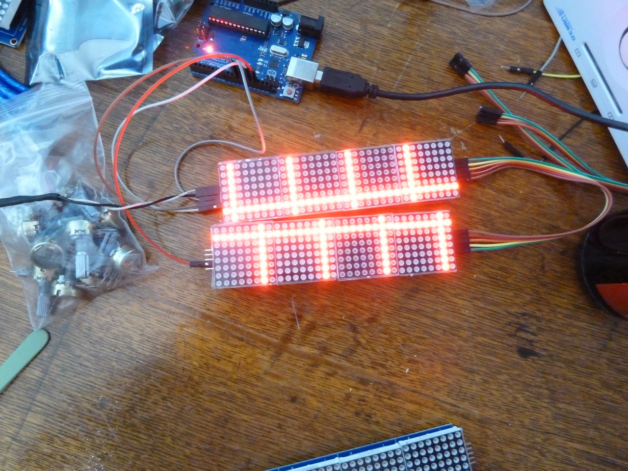
Fine. Cut out that single test (a blink test addressing all arrays simultaneously) and... Success. Several hours stable test loop running 512 LEDs from a single arduino!

P1010307.JPG


P1010298.JPG


I had originally planned one block of 256 LEDs per node, but they're pretty tiny - only about 1 1/4" wide. Now that I've proven the hardware works, I'm going to splurge a bit and use 2 blocks per node - 2048 LED in total. I've got a few ideas for how to display CPU load, but the blocks are in 2 groups of 8, and I have 6-core/24-thread CPUs. Eventually I'll polish the software up for different patterns and numbers of cores, but for now I'll be happy to just get the basics to work.

Now that I've sorted the hardware, I've started on the software side. Unexpectedly, this seems more obtuse than even the weird analog voltage issues I had. There are existing arduino CPU monitor packages, but they use old software that won't work any more, and they didn't compile properly on the tools available anyway. There are libraries for cross platform metrics that might work (Sigar), but they've been abandoned. Something like CPU-Z could be used, but it seems they've rolled their API off into a paid library.

To be honest, I loathe windows software development. I do old school C, php, and mysql. Windows development seems like an arbitrary labyrinth of random crap. It took 2 days of messing with projects in Visual C++ to even get Microsoft's own example code to compile!

Ugh.

However, perseverance has paid off. This very day I've managed to extract CPU performance info from Microsoft's Performance Data Helper library. I have yet to drill down in to individual core/thread %usage, but the counters are all there. After that, all that's left is to figure out how to send data to the arduino, and make a protocol for displaying the info on the LEDs.

I'm sure I'll be a while yet. Then I have to do it again for linux, because the cluster will be run on multiple OSes, because Software!

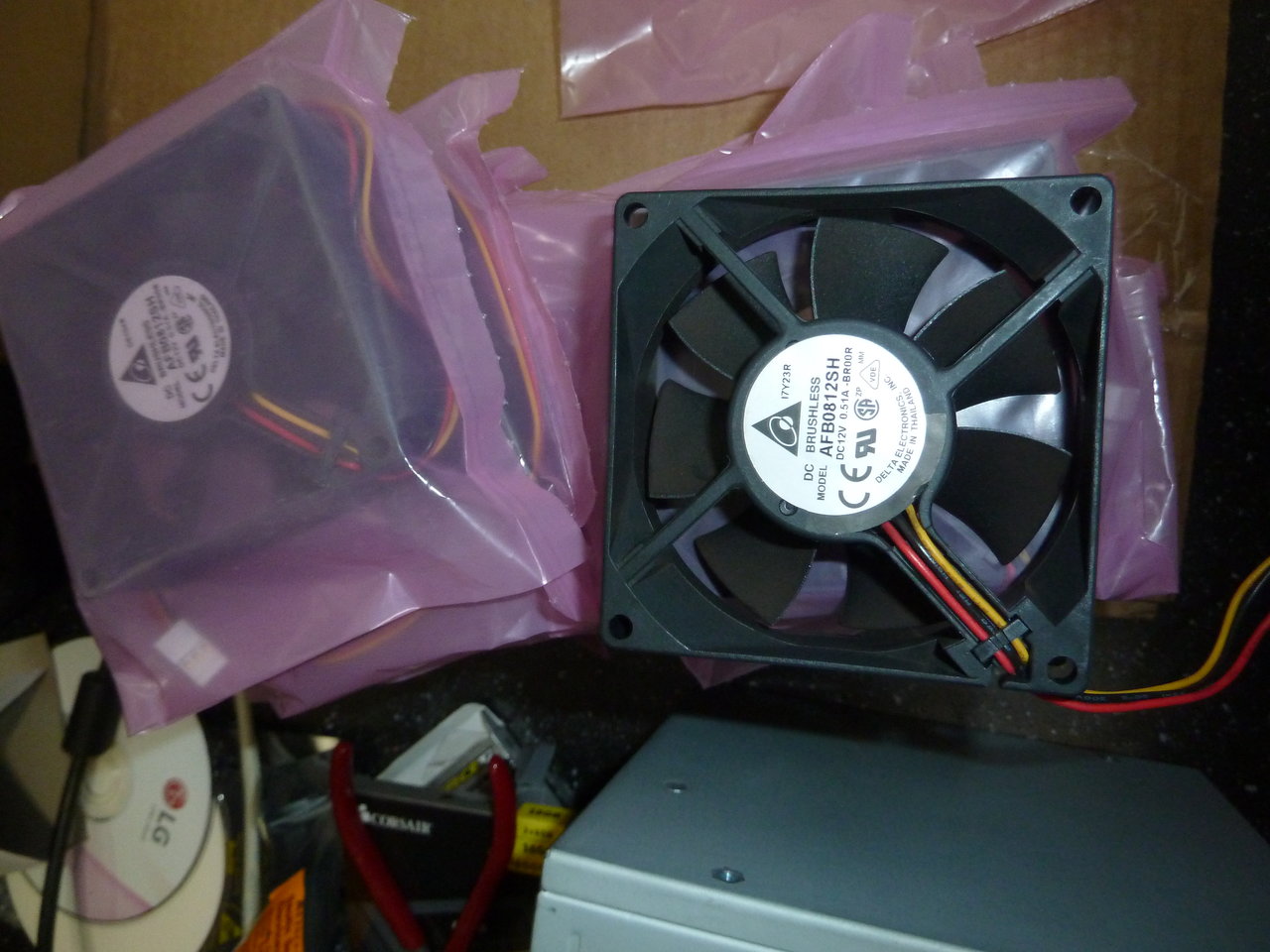
Lastly, I've taken delivery of the 80mm fans I'll be using. I got a deal on some delta fans, but they're a whopping 1/2 amp each, and are pretty loud. Not that I expected this cluster to be anything but deafening and hot :O

Oddly, these fans don't have the correct pinout. I'll have to re-wire the lot of them to make them work. I'll want to extend some of the wires anyway, so that's not a huge deal. The bigger issue is that I've got 4 fan headers, but 6 fans to work with. A common limit is 1 amp/header, and these fans are 0.51amp. Not sure if I can run two on a header or not...

P1010296.JPG
 
  • Like
Reactions: Derf
like this
So, more money spent.

P1010313.JPG


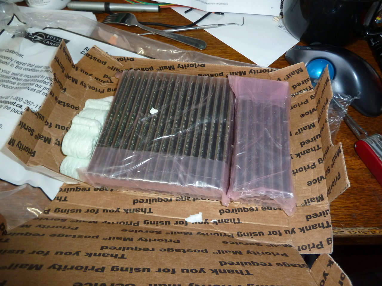
Brought in an additional 96gb of ram, so 192gb total for the cluster - 48gb/node and 24gb/cpu.

P1010317.JPG


P1010319.JPG


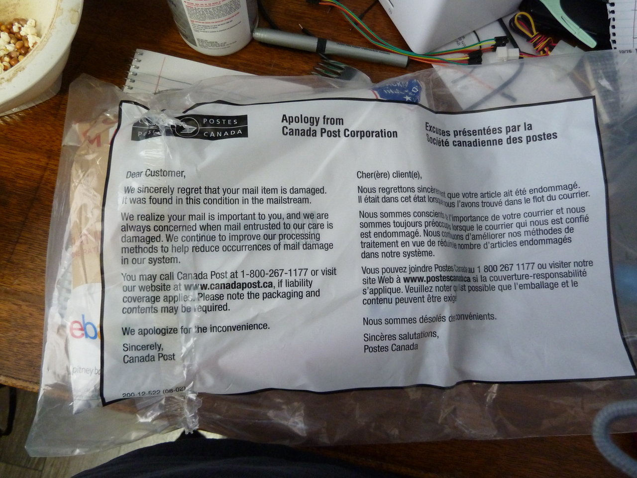
Once again, an eBay purchase gone right, despite arriving in this scary looking bag:

P1010309.JPG
 
Wow, that packaging. Amazing that they all showed up fine.

Looking forward to seeing the first rev of the case with all the LEDs.
 
Wow, that packaging. Amazing that they all showed up fine.

I can't say I was impressed but, sadly, that was not the worst-shipped ram I've received in the last couple of months. I had ordered some ECC ram for my file server - 3 sticks - and they shipped it in a padded envelope, inside of which each stick was in a to-size static bag.

This was shipped internationally. No support, no extra padding, nothing. At least the 96gb of ram had heat spreaders and was tightly bundled into a block - but these 3 were regular bare sticks, loose inside a padded envelope. Needless to say, one of the sticks was faulty, and when I asked they ship a replacement in more suitable packaging the response was along the lines of "We'll see". I decided to return it instead.

Looking forward to seeing the first rev of the case with all the LEDs.

It'll be a bit, yet. I can't find my C-clamps, so I'll have to get out to my dad's place to borrow his, and the power adapters haven't shown up yet. No more progress has been made with the Blinkenleds either. I'll also have to order more of the LED sets - I have 3, two of which will go on my main PC, and I'll need a total of eight for TM-b. Those take about three months to arrive :O

Once I get the C-clamps, I'll do some practice bends and hope I don't mess up too much material before I figure out how it works. Then I can bend up the first node and figure out how to mount the fans - for which I'll need to make another material run.

So there's a lot of what ifs and playing about before I have a solid plan on how to move forward. I haven't more than the vaguest of ideas how the stand for the nodes will go together after that.
 
So, a small update. I'm having problems with overseas shipments - anything from China is taking up to 2 months or so extra to arrive, for unknown reasons. That means I'm currently still short of fans, and, crucially, the ATX->Supermicro power adapters. The only thing new that I have received are a handful of stainless steel switches that will be used to power the systems on.

I haven't had any build progress, either. My time is currently being spent on insulating and drywalling my garage, so I can move in all of my tools and get an actual shop set up. I'll need that done before I can work on the system base anyway. With no power for the systems, and no way to build a base, there's a bit of metalwork I could do, but I'd want my shop to do finishing anyway, so no point worrying about that for now.

I'll post more as it actually gets done.
Most likely it is being held up at Customs. There is always a pretty significant delay going in/out of China, and that can be increased quite a bit if the company you ordered from is not very responsive to information requests from Customs. It's always something like specific values, weights, or pictures of the items.
 
Most likely it is being held up at Customs. There is always a pretty significant delay going in/out of China, and that can be increased quite a bit if the company you ordered from is not very responsive to information requests from Customs. It's always something like specific values, weights, or pictures of the items.

I hope that's all it is. I really want those ATX adapters - it's another $50 in parts and about 4 days work to make my own :(

It took 4 months for me to receive a package of switches, with no obvious extra customs investigation indicated.
 
I know it's madness, but if you were able to source the motherboards, why not the power supplies designed for them? No luck?
 
I know it's madness, but if you were able to source the motherboards, why not the power supplies designed for them? No luck?

These motherboards are pulls from a Cray cluster computer, afaik, powering pairs of boards at a time. Sourcing such things where I live is costly, to say the least. Not to mention the weird formfactor. I'm much happier adapting an ATX supply than trying that.
 
Back
Top