[Project Log] Wife said, 'Get rid of that nasty computer case' desk pc

Mungler

n00b
Joined
Oct 13, 2005
Messages
34
My faithful akasa server case has served me well for a long time, but now the time has come to move on. My wife hates the size of the case and has seen how little of the space inside is utilised so tasked me with downsizing. I took the opportunity to suggest 'getting rid of the case entirely' whilst rubbing my hands together with glee. This carefully worded statement led me to embark upon placing the computer in my desk. She did catch on after a while but, after agreeing to add some blue LED's, the project gained full approval ;)

So here is how it looks at the moment, complete with a chair stolen from the dining room.

My cunning plan is to put the components into the top drawer, complete with window and a nice custom water loop to replace the AIO cooler currently being used.


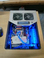
The front panel of the draw will have a dual rad mounted in it with fans drawing air into the space and a second dual rad will be placed into the top surface of the desk to serve as an exhaust (arrows in the picture indicating airflow), with the components and water loop items in the space in between. The I/O panel will emerge out to the underside of the desk where a cable channel already exists. The GPU is mounted flat, via a pci-e extension, to impede airflow as little as possible. The ports emerging as the I/O panel does.
The eagle eyed amongst you may have spotted my first challenge, that PSU.
Standing on its narrow side would allow the motherboard to be pushed back further making the cabling area safer, but will leave very little clearance for the rad.
I started a separate discussion about options for the PSU, including taking it apart. I'm still sitting on the fence regarding what to do here (I have invested in a bunch of temperature probes in order to investigate further.
In the mean time I move on to a physical mock up


Using a spare ATX PSU I was able to get a much better perspective on the problem. There is about 1cm of clearance between the PSU and the 'radiator'


With the PSU laid down I have a good clenched fist or 7.5cm of clearance for the rad but have to sacrifice space near the front and the I/O panel (and GPU ports) slide further into the realms of knee damage. For now, this is what I think I should go with. It will be simple enough to add a knee guard under the desk to prevent accidental port damage. Also I can flip the PSU fan so that it is pushing air up to the exhaust rad. I may decide to ventilate the leading edge of the PSU and block off the regular vent in order to keep everything in line airflow wise, but this is still being tested at the moment.

Next step will be design finalisation and kit purchase.
 
Last edited:
I really like this idea! "flip flop" looks better for air flow.
one thing I would suggest is moving the mobo and the res closer(maybe up and over the mobo) to the right side and run the cables out the back corner threw a small hole. if you need usb port access put a hub on the front of the drawer or just up on the desk. no port damage.
 
Why not swap the rear radiator and the PSU? This will make it so the air vents out the back, instead of the top. There's no unsightly hole costing you real estate on the desktop, and the airflow is encouraged to pass around the mobo, instead of over it.
 
You want airflow over the board to cool the chipset and only having the psu as exhaust isn't a good idea these days.
 
You want airflow over the board to cool the chipset and only having the psu as exhaust isn't a good idea these days.

Perhaps "around" wasn't the most accurate, I meant directly across the board, with the board directly in line with the airflow. Air would pass above and below the board, nixing the possibility of a pocket of hot air sitting under the board. And I wasn't suggesting using the PSU as exhaust, rather using the rear radiator as exhaust, so the airflow is straight front-to-back.

Of course, all this is omitting the fact that, unless the GPU is included in the cooling loops, having two 240mm rads might be unnecessary for just the CPU. You might have more luck (read "better cooling") with a couple of 120mm fans on the back, and save the $$ from buying a 2nd rad and fittings.

Mungler love the idea. Look forward to seeing where this goes.
 
I really like this idea! "flip flop" looks better for air flow.
one thing I would suggest is moving the mobo and the res closer(maybe up and over the mobo) to the right side and run the cables out the back corner threw a small hole. if you need usb port access put a hub on the front of the drawer or just up on the desk. no port damage.

I considered this for a while, but when tested in the mock up several new problems came up. Simply shifting the mobo right until it touches the mounts for the res did not give enough clearance for cables running into the I/O, putting a lot of stress on them. I thought about raising the res and mounting it to the side wall but i think the ram module placement on my current board would mean I wouldn't be able to move it far enough to make a difference. It would also mean that the chance to add a ram cooling water block later on would be more of a major rework. Thanks for the suggestion.

Perhaps "around" wasn't the most accurate, I meant directly across the board, with the board directly in line with the airflow. Air would pass above and below the board, nixing the possibility of a pocket of hot air sitting under the board. And I wasn't suggesting using the PSU as exhaust, rather using the rear radiator as exhaust, so the airflow is straight front-to-back.

Of course, all this is omitting the fact that, unless the GPU is included in the cooling loops, having two 240mm rads might be unnecessary for just the CPU. You might have more luck (read "better cooling") with a couple of 120mm fans on the back, and save the $$ from buying a 2nd rad and fittings.

Mungler love the idea. Look forward to seeing where this goes.

I think I get what you mean. There is almost zero clearance behind the desk, so an exhaust in the rear would be practically flush with the wall. I did for a moment consider mounting the rad on the other side of the wall (it's an external wall) but this was veto'd by the boss. I recently saw the article for the new corsair sf series psu, but I will have to explore all other options before I commit another hundred being spent on this project.

Also, yes the gpu will be part of the loop.


I have some plans forming for the exhaust area so that it is not just an ugly hole. Watch that space.
 
Last edited:
still tweaking the design so no real life photos yet. Itching to get started on this but, as with all projects, get things right before you pick up the tools.
The top section had to be a window as this was one of the main features of the desk build (plus the boss wants to see lights), but along with the window, I also had to put in enough material to provide a sturdy mount for a double 140mm rad and its fans as I would be taking away most of the wood.

I have added a representation of the desk surface so that I can properly visualise the window section. The rear portion will be a metal plate for mounting the 140mm fans/rad. The metal plate will have a lip on the rear so it can be secured to the desk surface. In addition to that on the closest part of the metal plate, from left to right on the image, a small square hole for a pair of USB connectors 3.x obviously, a 5.25'' space for mounting a fan controller and finally the round hold for the power switch.
 
Last edited:
Time for an update. It has been slow going as I foolishly decided to move house.
However:

Parts List:
CPU Block HEATKILLER® IV BASIC (INTEL processor) ACRYL CLEAN
GPU Block HEATKILLER® GPU-X³ GTX 680 "Hole Edition"
Radiator x2 Alphacool NexXxoS XT45 Full Copper 280mm
fans x4 NF-P14s REDUX PWM 1500RPM 140mm Quiet Case Fan
reservoir + pump D5 Photon 270 Reservoir/Pump Combo
fittings 10 compression fittings. 5x 90 degree 5x straight
fan controller Speed Touch 6 LCD Fan Speed Controller
kill coil Silver Anti Algae Kill Coil [PMSKC1] from XSPC Online Store
and a pci-e extension cable.
Sorry for the slightly blurry pic. I was shaking with joy. Still got a few more bits to source, but well on my way to getting started.
 
Last edited:
a flurry of activity recently. I started work on the top section that would house my exhaust vents, fan controller, power button and USB ports.
I cut the rough design but have left the back long so that I can bend and trim it later. I started withe the hole for the 5.25 fan controller

The edges of the mount were a bit rough. I didn't spend long filing them as it was something that was not going to be seen. What i did do (not shown in the next picture) was get some kapton tape to ensure no contact outside the screw clearance areas

That was just a try in. I have noticed this picture was taken before I removed the masking tape and filed the edges. it looks a bit better than this now. It was a bit of a struggle to get the bends at the right level for the fan controller mount points. Being a bend that is not on the edge of the material meant I could not use the bending machine on it so I had to go freehand with pliers and a hammer.
Despite being my first time doing this kind of build. I'm pleased with the results so far and have learnt a few things in the process:
- Digital calipers are great
- Don't manually bend metal exactly on your measured edge. Allow some extra material so that the bend doesn't spread outside your area.
- Don't just measure on specs. Measure the real thing (as sometimes the specs don't quite tell you the measure you are thinking).

Next up will be the radiator/fan holes and mounts.
 
Last edited:
taking advantage of the long summer evenings I have surged on with preparing parts. I got these sexy lian-li fan grills which proved quite hard to find in stock anywhere. I love the honeycombesque mesh and the rounded edges. But I could not find any templates for cutting holes for them and the warning of 'Works for Lian-Li Case Only' made it obvious that i would get little help. Not wanting to ruin the piece of metal I already started on. I made a template.

I was very happy with this and the fit was nice and tight so I went ahead and cut the holes on the top panel

I have not yet decided on a finish for the metal section yet. I'm thinking of cleaning them up and giving it a brushed finish. The black and silver contrast is quite nice and doesn't seem to clash with the silver/copper/blue effect that will be going on inside the desk.
At this point I just have to add a 16mm hole for the power button and this section is finished. I'm leaving the USB hole out for now as I don't have a clear method for mounting the ports.

Next up will be the front facia
 
Last edited:
you could get one of these and mount them with screws anywhere convenient.

2 Port Panel Mount USB 3.0 Cable - USB A to Motherboard Header Cable F/F

edit: looks good!
Thanks. That type of cable was my first find and I was going to screw it to the plate but, on reflection, I liked the cleaner look on the front portion of the plate. I've already found a slight variation on the cable posted in your link here. My thoughts now are to get some square nuts or similar (something like this) and spot weld them to the plate, screwing them to this to leave a flush port on the presentation side. Using square nuts as the give a bit more surface for spot welding.
 
As an Amazon Associate, HardForum may earn from qualifying purchases.
so with the USB port issue still rolling around my head I decided to crack on with another portion of the desk computer, the front fascia.
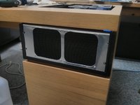
After measuring up the size of the rad I cut out a new drawer front

The rad has to be mounted slightly off centre as the chambers for the inlet and outlet, if you consider the line between the two fans the middle, is longer on one side.

There is a pencil line on the exact mid point of the drawer I tried to strike a balance between material left on either side of the rad and the centreing of the fans grills. I also had to get some short screws. The Lian-li grills came with some fat screws that would never have screwed directly into the rad and the fans came with thinner screws but they were too long (as they expected to used through the fan)
I then moved on to mounting the fascia on the base plate. The idea I have here is that for ease of maintenance, be that draining the loop, upgrading components, etc. I could do with an easy way to get at the system. Obviously I was going to have a window in the top surface of the desk which could easily be lifted out for access, but felt it better to have a full removal plan. So I came up with spacer brackets.

two brackets that leave a gap between the base plate and the fascia. This is to allow the base plate to drop flush with the drawer front when it is fully inserted, helping to hold the whole thing firmly in place.

As you slide the system in, the top of the front fascia has about 1-2mm of clearance. When fully inserted the base board drops slightly to straddle the existing wood of the desk draw giving a flush floor to the whole thing.
The astute among you will have spotted the piece of wood along the top edge of the draw. I will need to remove this before final installation. For now I have not gone beyond any point of no return regarding the desk itself.

next up is the front plate to cover the rad on the fascia.
 
Last edited:
now that I have moved house and got things a little settled. I spent the xmas break doing the desk build. I am happy to report that I have now completed the build. A full gallery of the pictures can be seen here. Unfortunately I had a bit of a mix up with my web hosting solutions so have misplaced some of the previously posted pics. But I took a number of new ones to keep you going.

IMG_20170125_185658.jpg IMG_20170125_205302.jpg

I hit a few bumps in completing the project which I'll try to outline here for those that may be tempted to do their own draw conversion.

  • the orientation of the cpu waterblock is important. Given the generic mounting solution I had I thought I could mout the water block any way round. but the components near the CPU slot had something to say about that. I had to turn the waterblock 90 degrees and then re think my pipe runs.
  • even though I made a template for the window hole to guide my router. I made the fatal mistake of not remembering to turn it over when I switched from working on the bottom of the desk to the top. this meant that my hole is off by about 1cm which is really quite annoying, but something that I can remedy with a bit of edging strip that I purchased.
  • sleeving and resleeving cables is super easy and I thoroughly recommend doing it to make the scheme in your build that little bit more coordinated (also you can save yourself a bit of cash by not having to purchase 'custom' ones.
  • remember a drain! and make it accessible. I remembered that I was going to put a drain in at the last moment. drilling a new hole after painting everything is a nightmare and you'll be grateful that you can do water changes more easily.
    to do this I took the exit tue from the front rad (the last component in the loop before returning to the pump) and cut it about 5cm from the fitting. I kew this was going to be tricky to refit but it allowed me to drill a hole for a bulkhead fitting which I tee'd off the original pipe. Now I have a blanked off plug on the under side of the baseplate (accessible from the cupboard below) to which I can attach a valve and another length of pipe for draining. You can't get lower than that :)
  • on the io holes I decided I needed a little more insurance against accidental leg/cable interfacing. So I simply added a couple of stylish kitchen door handles along the lower edge to guard against it.
  • The bit I had the most fun with was squeezing the GPU mounting bracket flat in a vice :D
I did not upgrade any of the components of the PC itself so I am running a geforce gtx 680 and an i5-3570. I have not overclocked anything on the machine. At idle, the cpu and gpu sit at roughly a 10 degree delta with the fans entirely off. With the fans at just slightly under 1600rpm that delta drops to 7 degrees. But that is way to loud for me. The pump has been set at its second lowest speed. So when the fans are off, the PC is 'literally silent'. The odd thing I have noticed is, I tried doing some gaming on this machine and I could leave the fans off then too! I know I overspecced the rads a bit (to allow for future upgrades) but I never expected to be able to run the witcher enhanced edition, 1900x1220 resolution at max settings for well over an hour without it getting warm. I moved on to a more demanding title (not exactly bleeding edge though), elite dangerous, again at high settings things would get toasty when flying into a docking stations (lots going on in there) and temps still didn't get over 50 degrees (31 degree delta). So, with the fans running at 900rpm I get almost total silence and know that I am getting enough cooling.

Thanks to everyone for following along and the handy comments I received. I'm happy to answer further questions on the build if anyone has any. but for now I'm busy using it! :D
(at least until the 1080ti comes out and the vive drops in price then it's upgrade time)
 
Back
Top