NUC-romancy: Gigabyte "Brix" GB-BSi5H-6200

RazorWind

Supreme [H]ardness
Joined
Feb 11, 2001
Messages
4,646
With my humblest and most sincere apologies to the [H] member who sent this little guy to me for taking as long as I have to get around to making this thread, it's time for some... NUCromancy.

Eh? Eh !? :D

On the bench today is a Gigabyte "Brix" (I think?) GB-BSi5H-6200 NUC, which according to its owner, doesn't turn on anymore. Unlike a graphics card, there isn't really much to be learned with the housing on, since we can't measure anything on it. You'll have to take my word for it, but it really is dead. I tried turning it on, but... nothing.
yepitsdead.jpg

So, let's get it cracked open.
lidoff.jpgallapart.jpg
board1.jpgboard2.jpg

Texel bamboozled my chair when I stood up to take the photos, but it's hard to get upset with him.
texel.jpg

He's fascinated by almost anything that happens to be on the bench, but he LOVES to steal the little cut tapes with SMD components inside, which is a recipe for chasing him around the house for ten minutes to take it away from him.
texel2.jpg


Now, let's get after the board. Diagnostics on this should be, fundamentally, the same as on a graphics card. We clearly have a power issue of some kind, so there's a great chance that our big logic ICs like the CPU are fine.

One of the key differences between this and a graphics card is that we only have one power input, which is located at this barrel jack. First thing we should test for there is, do we just have a short straight through the jack?

Nope. This looks good.
noshort.jpg

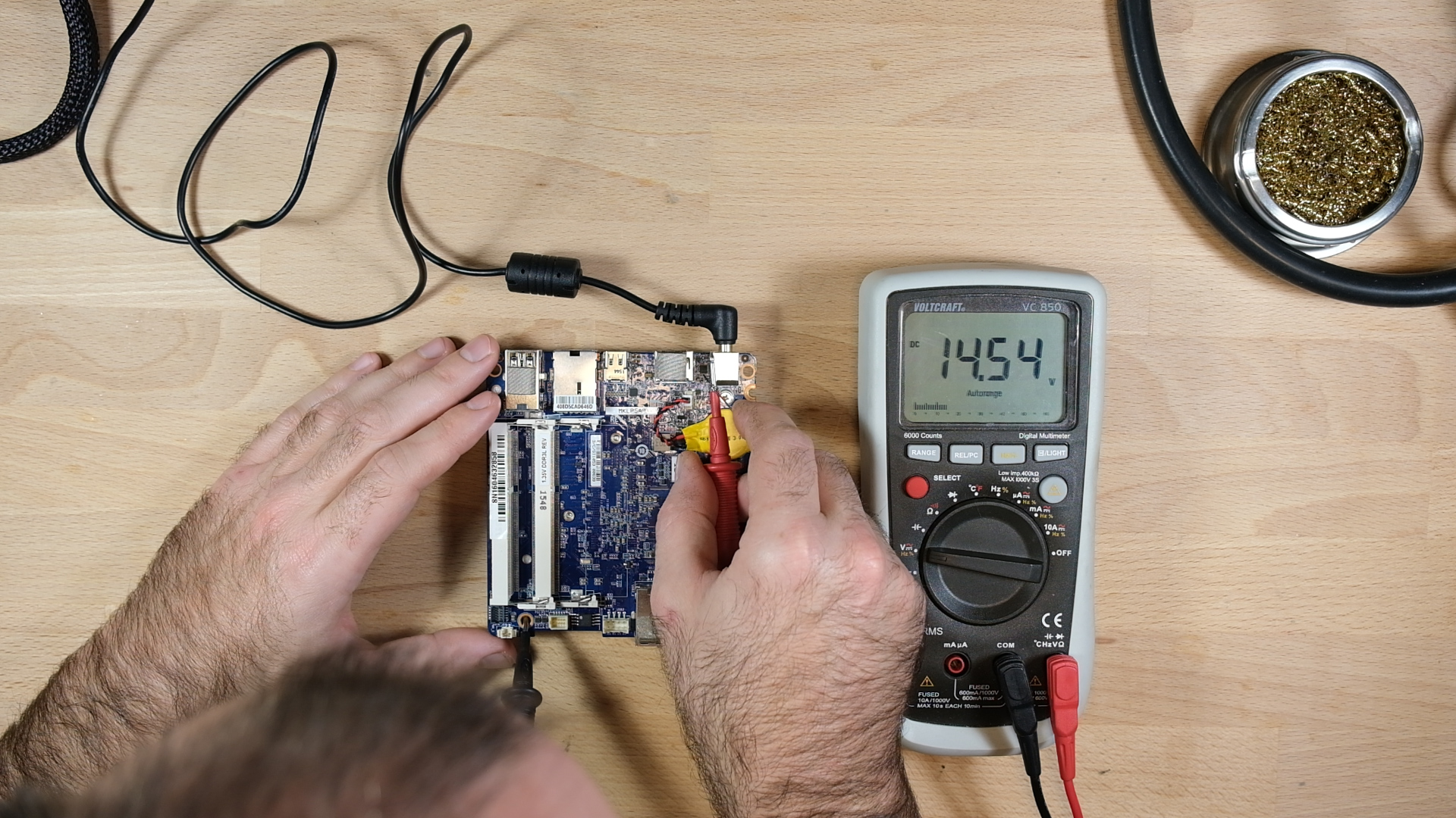
Ok, we should also have tested this before, but the power brick is actually working, right?

Yep. (In reality, I did test it before, but I just didn't take a picture)
powersupplyok.jpg
 
Alright, moving right along, I plugged in the power connector, and started taking measurements on the board. What we're looking for here is what power is getting to, and what it's not.

Testing for voltage at the barrel jack. Looks good.

power_jack.jpg

Ok, so the traces on the board connect the pin at the jack to this MOSFET next to it, which seems to be there to help control the process of starting the board up. We've got voltage on the drain side...
power_mosfet.jpg

...but not on the source side. What that tells us is that the MOSFET isn't being turned on.
no_power_mosfet.jpg

Another thing I checked for is voltage at the power button, but no dice. That was a long shot, but worth checking.

no_power_switch.jpg

Ok, so we need to figure out why that MOSFET isn't turning on. If you look at this image, you'll see that the traces go from the +19V pin on the barrel jack to the drain side of that MOSFET, through the MOSFET, and along another trace, to another MOSFET. Notably, there is a capacitor on that trace, with the other side connected to ground. Also note that the gate pin on that first MOSFET is connected to an IC we'll talk about in a moment, the APL3542A.

Click on this image to enlarge it, if you need to.

magnified_1.jpg
 
Alright, the aforementioned Anpec APL3542A... Here it is, next to the barrel jack, opposite the MOSFETs.
Datasheet here:
http://www.anpec.com.tw/ashx_prod_f...17011316223128.pdf&original_name=APL3542A.pdf

APL3542A.jpg

What this IC does is control whether power is available to the rest of the board, subject to a series of rules:
1. It needs to have power on its own power supply pin (pin 1)
2. It needs to be told to turn on, via its enable pin (Pin 9)
3. It enforces over current protection by measuring the voltage drop between pins 10 and 3 (input reference voltage and current sense, respectively)
4. It imposes a delay in powering up, based on the value of a capacitor on pin 6
5. Maybe some other stuff, I don't think it's relevant to us now.

Pin 4 is connected to the gate on our MOSFET 1, referenced above. When the APL3542A decides it's ready to power up, it produces a voltage on pin 4, which turns on the MOSFET, and allows power to be supplied to the rest of the board (or at least to the second MOSFET). For whatever reason, this is not happening. Let's troubleshoot.

Pin 1 - looks good.
apl3542A_pin1.jpg

Pin 2 - also looks good This supplies power to the gate pin power supply. So, something greater than 12ish volts goes in here, and then comes out on pin 4 as whatever voltage is configured for the MOSFET's gate pin.
apl3542A_pin2.jpg

Pin 9 - Looks healthy. This is the enable signal. It tells our IC to start up.
apl3542A_pin9.jpg

Pin 10 - Input reference voltage. If my reading of the datasheet is correct, this is dead center within the range we expect on this pin.
apl3542A_pin10.jpg

So, what all that tells us is that we should be getting something on the gate pin output to turn on our MOSFET and power the board up. But we're not.

One possible reason for this is that we actually are, but then we draw too much current. We've established that we don't have a short to ground right at the barrel connector, but we might have a short to ground downstream from it that's causing our over current protection to trip. Let's check that.

Aha! If we check the resistance on one end of that capacitor in between the two MOSFETs, we find that we do, in fact have a short to ground right there.

short2ground.jpg

Furthermore, if we measure voltage at that spot as we plug in the connector, we'll find that we actually do get a little voltage momentarily. So, we're tripping the overcurrent protection, and the APL3542A is shutting us down to keep from damaging anything else. Cool, huh?
Sequence 01.gif
 

Attachments

  • apl3542A_pin2.jpg
    apl3542A_pin2.jpg
    1,012.2 KB · Views: 0
So, what do we do about it? Well, ordinarily, you'd have to do something like voltage injection to figure out which component in the circuit is causing the short, but if you remember the image with the two mosfets, you may also remember that that second mosfet is isolating this part of the circuit from the rest of the board, so the only component attached to the circuit is that MLC capacitor. As it happens, MLC capacitors are quite prone to failing this way, so I think we can skip straight to just removing the cap from the board, and checking to see if our short is cleared.

Flux on.
fluxon.jpg

Apply heat.
heat.jpg

And it's off! It's important to move quickly in situations like this, since the board has those two MOSFETs right there, which can be damaged by the heat from the hot air station, and also the barrel jack, which is made of plastic, and could melt.
itsoff.jpg

After it cools down, we check for a short, and... It's cleared! Where we had zero before, we now have 140K.
noshort2.jpg

We can confirm by testing the removed capacitor. Zero ohms through it, so that means it's our culprit.
measuringdeadcap.jpg

So, our next step is to get our hands on a good cap to replace it with, and solder the new one on there. For that, I have to pay a visit to Digi-Key, so we'll reconvene once I've got it in hand.
 
Alright, parts are ordered, and video version is up on Youtube, for those who like those.


I had to guess as to the capacitor value, but I went with 22uF, which is literally the highest value that exists in that size.
 
I was reminded earlier this week that I never followed up on this. We'll get to why later, but the story continues. I should note that this post is actually weeks after the fact - I'm pretty sure I shot this back in December.

Our next step was to get our hands on a replacement capacitor for the one that was shorted. Here, from digi-key we have a tape of replacement capacitors. These are 22uF made by TDK.
IMG_4612.jpg

Next, we'll clean up the pads on the board...
IMG_4613.jpgIMG_4614.jpg

CAMB5210.00_01_17_15.Still005.jpg

And solder the new cap into place.
cap_install.jpg

IMG_4615.jpgIMG_4616.jpg

After the board cooled down, I checked to make sure the short was still cleared. Yep, it is!
short_still_clear.jpg

Now, it's time to clean the flux off the board, put the heatsink back on, and test it.
cleaning1.jpg

I also cleaned the old gross thermal grease off of the dies, while I was at it.
die_cleaning.jpg

Heatsink on, we're ready to test. Keep in mind that what would happen before is that we'd power up the whole board for a few milliseconds, the APL3542A would freak out over the short to ground, and shut off. That being the case, the way we'll be able to tell if our short is cleared is that we'll continue to have 19V (the output voltage of the power brick) at our replaced capacitor, which is on the right side in the photos above.
heatsinkon.jpg

Next, plug in the power... We're not seeing any smoke or fire, so that's a good sign...
pluggedin.jpg

Now, we'll test for voltage. 19V is what we're expecting there, so we should now have power to the various buck converter inputs on the board. This is a minor victory!
19v.jpg

I reinstalled the fan and made a couple more voltage checks. We've got 5V at the power button, so that's a good sign. It means that the input voltage is getting to somewhere on the board that contains a buck converter that steps that down from the 19V input.
5V.jpg


I also did a check at the input to the two main logic VRMs. I'm actually not sure which is which, but the fact that we have 19V here means that our APL3542A is not freaking out and shutting us down.
19V2.jpg

At this point it was time to plug in a monitor and see if it works.
CAMB5210.00_06_59_19.Still011.jpg

But.... Nothing happens. The board is still dead. Why could that be?
nothing.jpg
 
Back
Top