My PowerMac G5 Build Log

nalc

[H]ard|Gawd
Joined
Sep 25, 2010
Messages
1,077
I wanted to attempt an interesting project. I always have liked the way PowerMac G5 cases have looked since launch date, but I don't want their lame hardware. I was lucky enough to score a complete dual G5 rig with a dead mobo on ebay, to use as the basis for this project. I'm going to do a gaming rig in it. This means provisions for good aircooling, full ATX mobo, one each of optical, mechanical, and solid state storage, and a powerful PSU.

Since we're getting near to launch date, I'm holding out for Sandy Bridge, but I've gotten everything I could:

CPU - Sandy Bridge, will pick up early next week at Microcenter
Mobo - Sandy Bridge, will pick up early next week at Microcenter or online
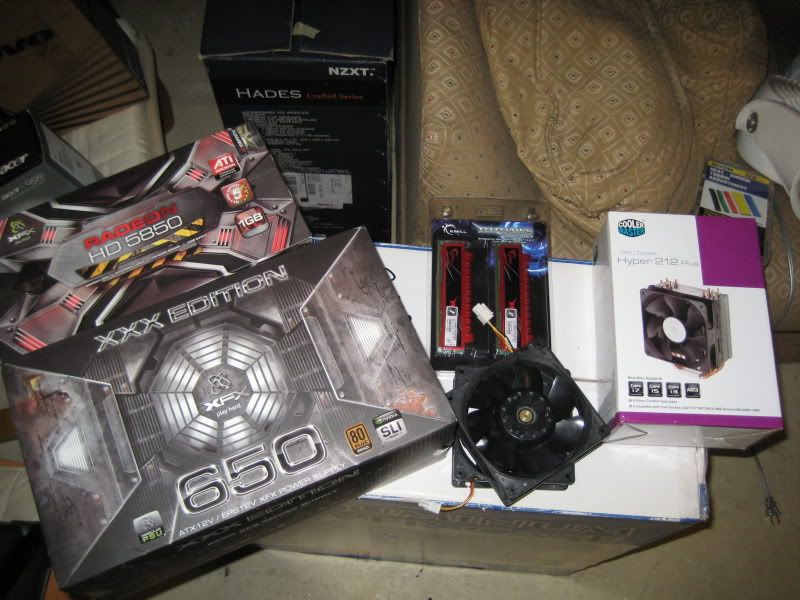
RAM - 2x4gb G.Skill Ripjaws DDR3-1333
GPU - XFX Radeon HD 5850
GPU2 - XFX Radeon HD 5450 (maybe, if I want to use it to run to my TV as a third monitor)
PSU - XFX "XXX Edition" (I kid you not, I think they get paid by the "X". So many freaking X's, since I'm currently running an Xeon X3210 core2quad)
HDD - Samsung Spinpoint F3 1tb
SSD - Intel X-25M 120gb
DVD - Some generic SATA DVD burner pulled from a broken HP desktop from like 2006
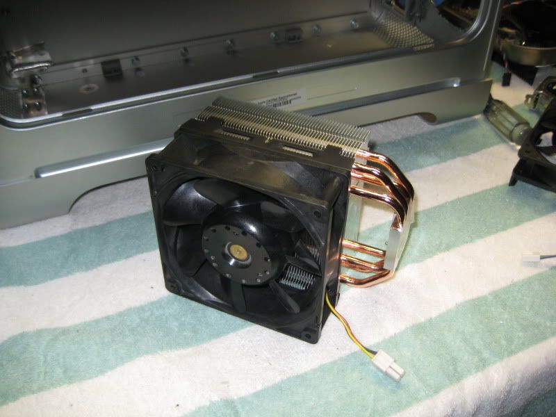
HSF - Coolermaster Hyper 212+
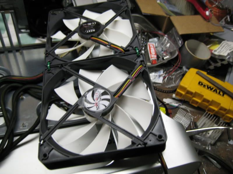
Fans - 2 x San Ace 120mm, 1 x Delta 120mm? Not sure on third or forth fan yet.

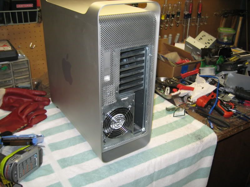
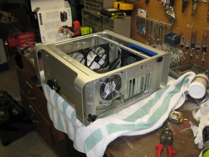
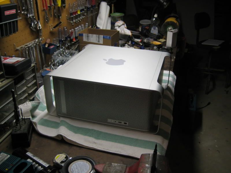
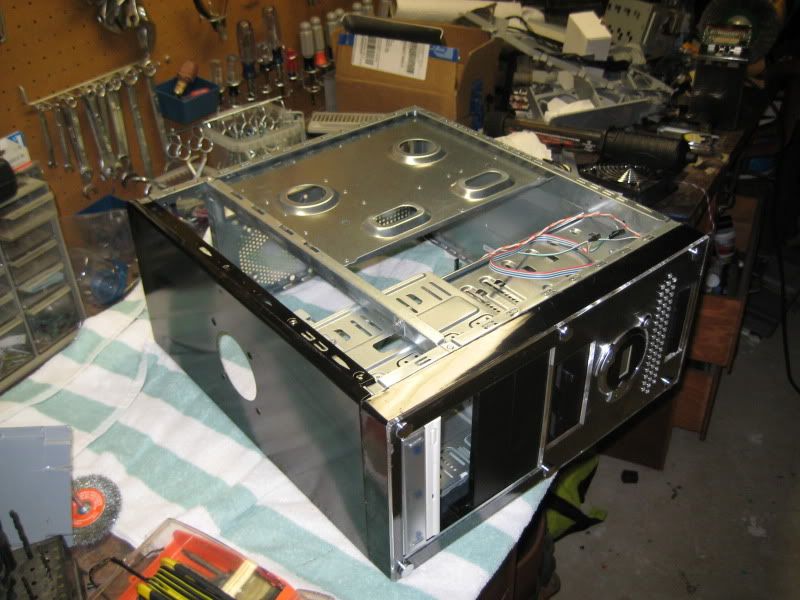
On its side, like a beached whale.
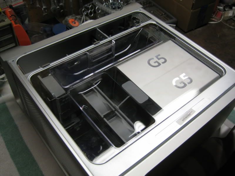
IMG_3758.jpg


And, opened up
IMG_3759.jpg


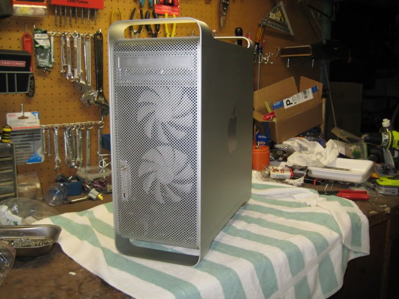
It's about the size of a regular ATX midtower.

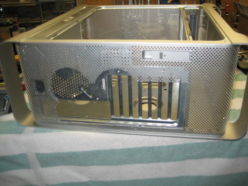
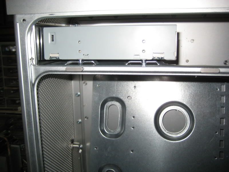
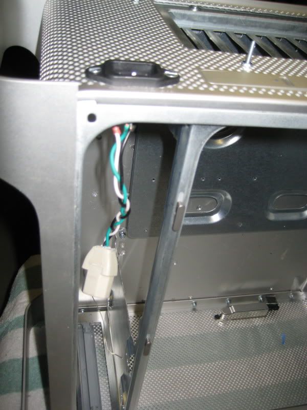
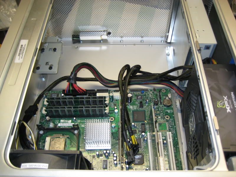
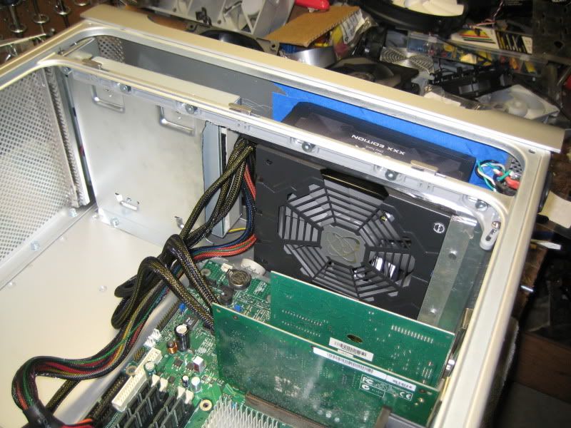
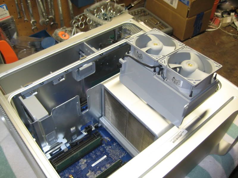
The inside is where things get dicey, though. There's a shelf for the top 20% of the case. Above the shelf is the DVD drive and two hard drive bays, with a small cooling fan.
Below the shelf, taking up about 70% of the rear panel is the motherboard. It's a non-standard size. It's very wide, going the full depth of the case. It has four PCI slots, but the I/O panel area is somewhat longer than normal. It's roughly the size of two microATX boards side by side.
Below that is the PSU, taking up the last 10%, about 2" total. It's wider and longer than a normal PSU, but a little bit shorter.

There's the easy way to mod this. You keep the top shelf as is. You put in a MicroATX mobo tray. You open the Apple PSU casing, remove the circuit board, and replace it with the insides of your PSU. Even though the Apple one is shorter, it has two fans in the front. So for a normal PSU that has a 120mm fan on the top, with that fan removed it can fit height-wise in the Apple PSU casing, and be cooled by the two fans blowing front-to-back. Nice and easy.

Not wanting to void my PSU warranty or spoil its good looks or deal with two noisy 60mm fans (I have shocked myself by picking up a bare PSU circuit board while it was running and powering my computer, I'm not afraid of hurting myself doing it because I've been there and done that and it put some hair on my chest and that's about it.), I didn't want to take mine apart to put it in that housing.

This created a conundrum. With my trusty measuring tape, I deduced the following:
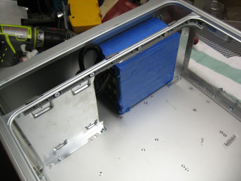
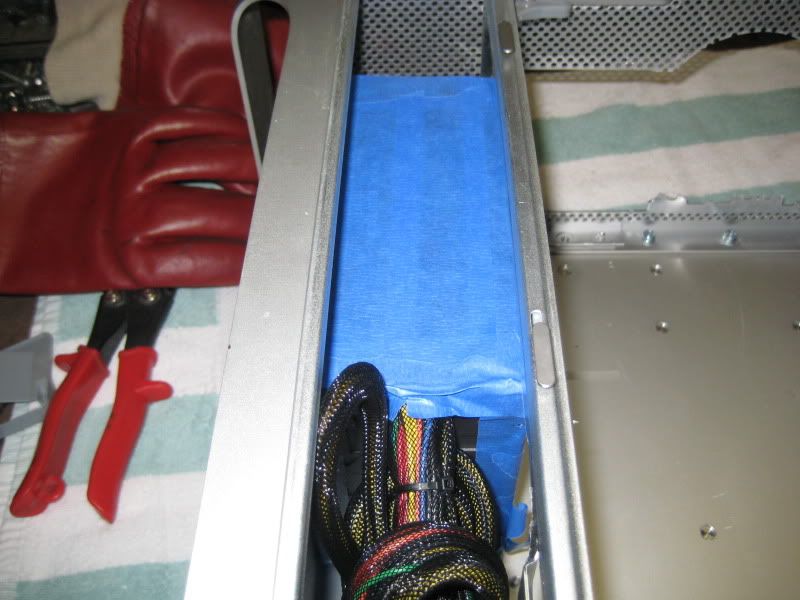
The case was not tall enough for me to fit the mobo tray and the PSU vertically. I'd either have to go mATX, which I didn't want to do, or find a different spot to put the PSU. I wanted to see if I could put it in front of the mobo, facing downwards (think Lian Li PC-A05) but the case wasn't deep enough, and I didn't want to have the PSU with the fan in a vertical orientation because it would block airflow through the front of the case.

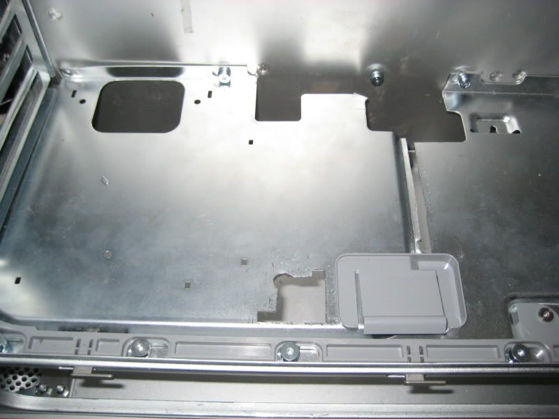
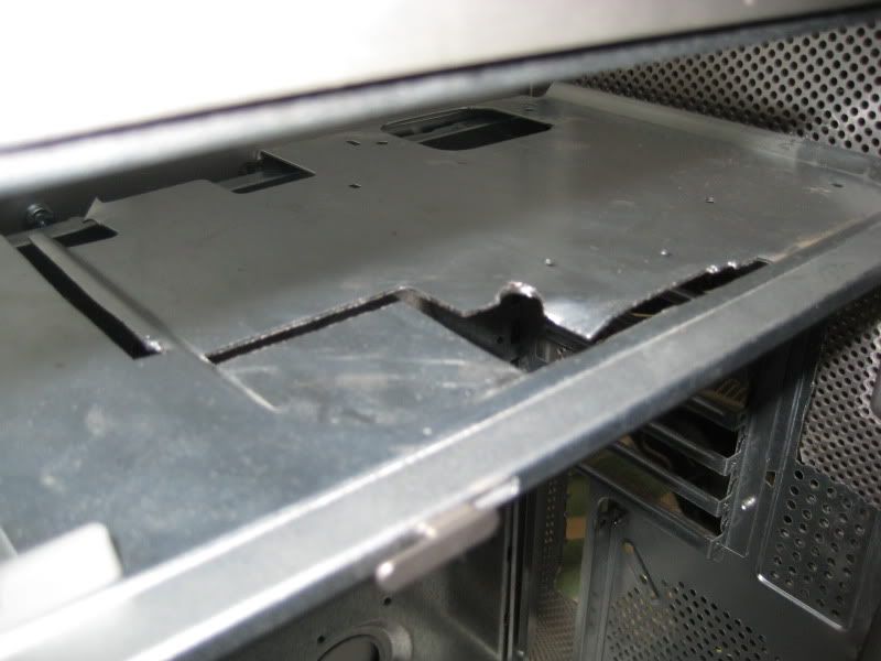
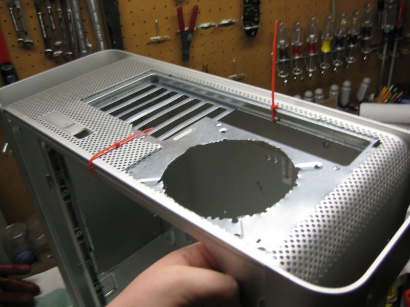
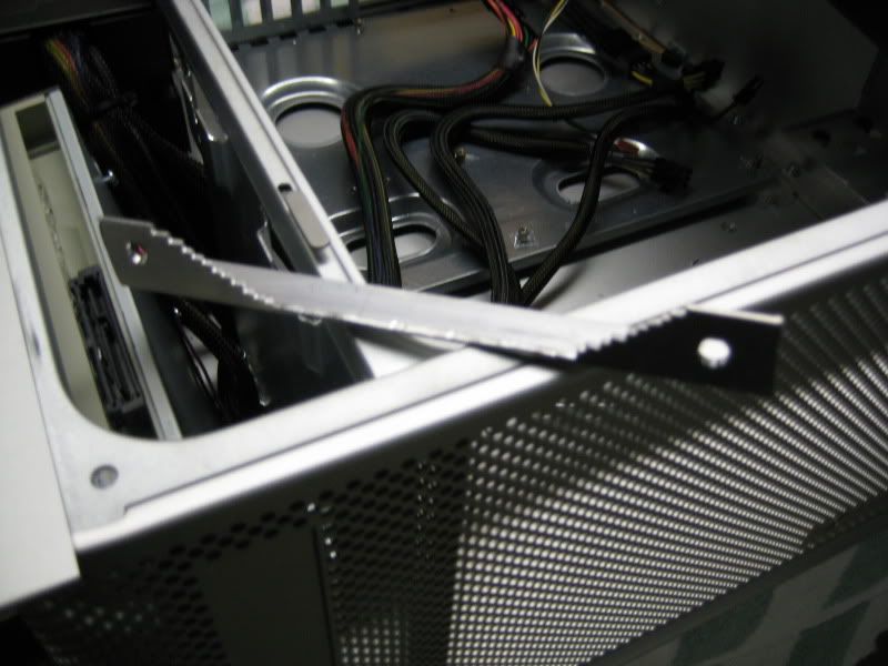
So, I knew that I had to rip out the HDD cage and cut a hole in the shelf.

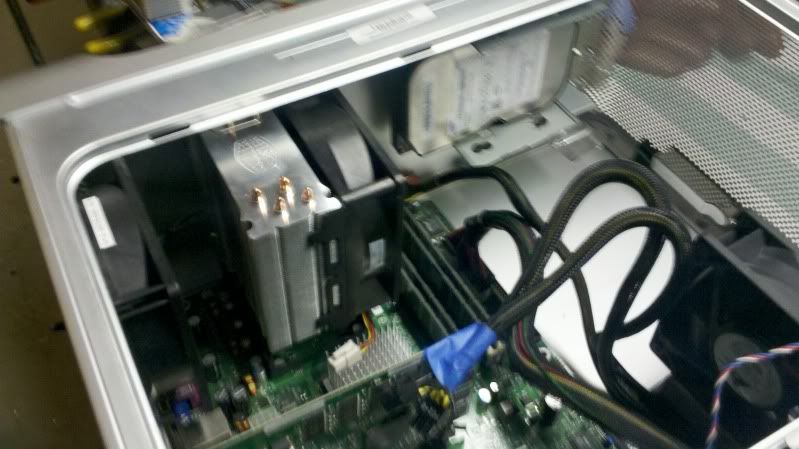
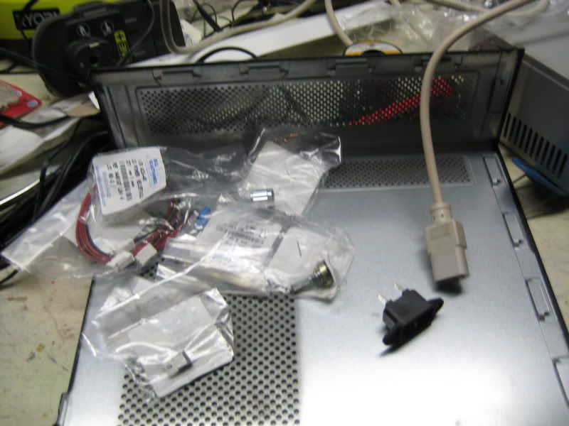
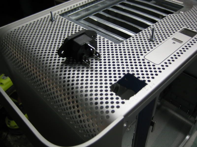
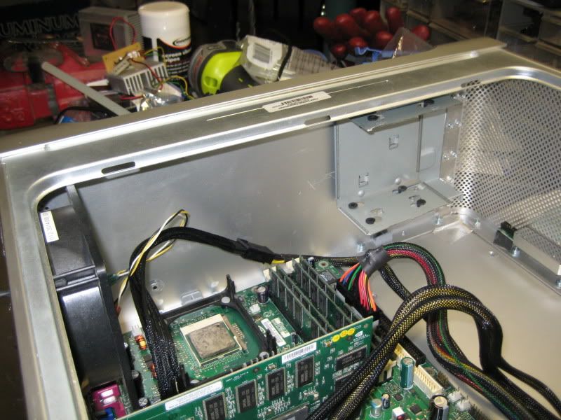
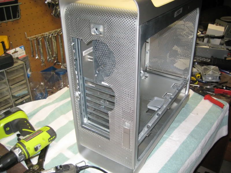
I took out the Apple crap
IMG_3762.jpg

And then realized, to my dismay, that I couldn't remove the CPUs. Apple makes it weird. In the normal case, mobo is mounted to the case with standoffs. The CPU is mounted in a socket on a mobo, and the HSF is held onto the mobo with some sort of retention mechanism.
In a powermac G5, that's not true. The mobo is mounted to case standoffs. However, it has holes above some of the standoffs. The CPUs are mounted on small circuit boards with the voltage regulation circuits, which are then permanently attached to large heatpipe heatsinks. So you put this big CPU/HSF assembly onto the mobo, then screw it directly to case standoffs.

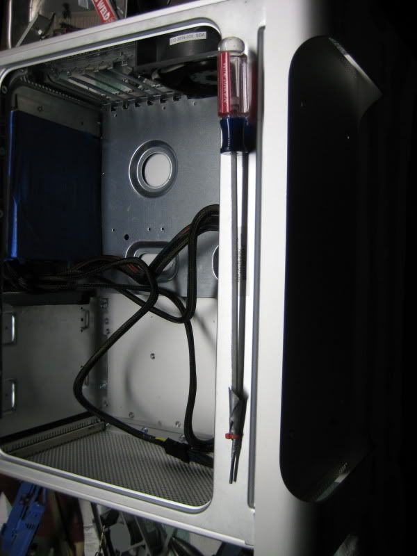
This was the first major challenge, but far from the last. To get the CPUs off required a 2.5mm hex wrench. This was fine for the screws around the edges, but there were also screws in between the fins. To get to them, you need a 2.5mm hex that is at least 8" long, because you need to slide it into a narrow gap between heatsink fins, all the way to the screws on the back of the case. Obviously, I didn't have a tool for this, so I ended up taking a cheap L-shaped hex wrench that comes free with furniture from Ikea or whoever, and bending it flat. I then duct taped it to the end of a long flathead screwdriver, and reinforced it with some zip ties. This was able to get me enough leverage to get to those stupid CPU screws. Once I got those out, the mobo and PSU went very quickly, and I noted the poor design requiring that the mobo be removed in order to take out the PSU.
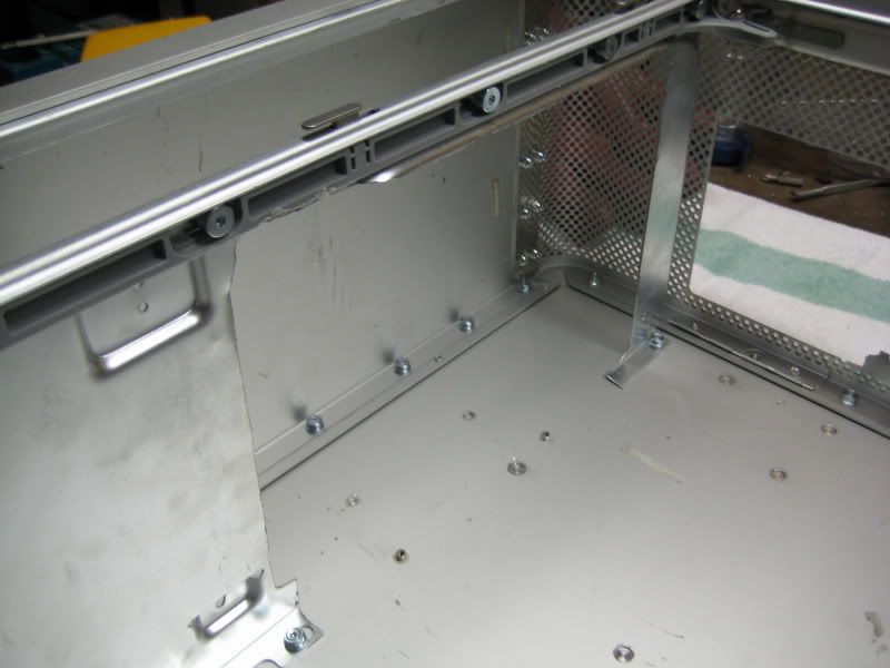
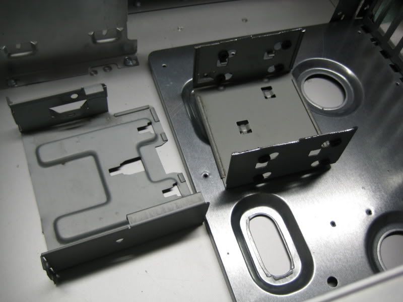
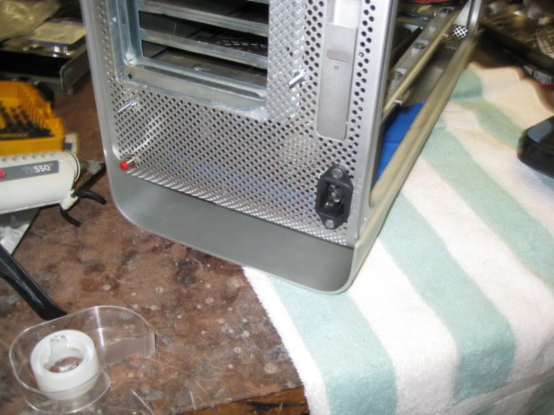
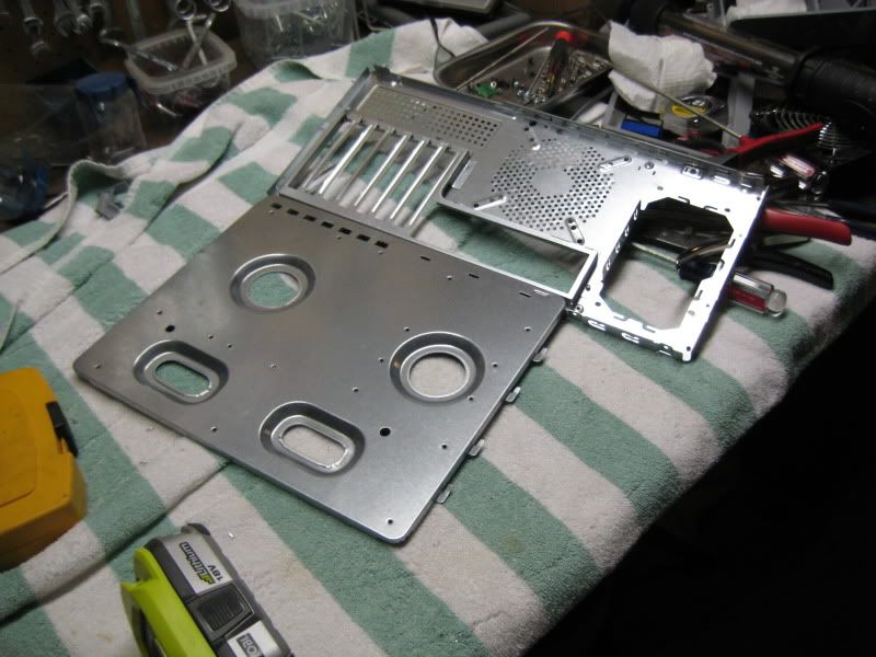
The empty case:
IMG_3766.jpg


The donor case that I got the mobo tray from:
IMG_3764.jpg

IMG_3765.jpg


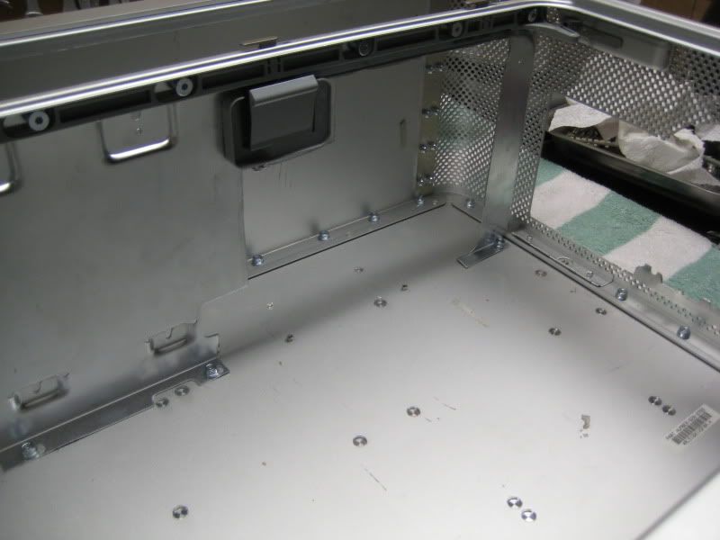
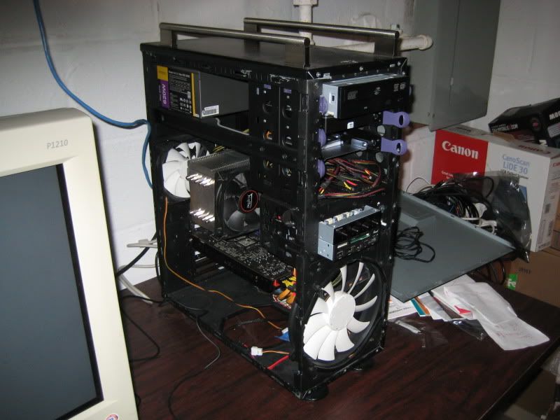
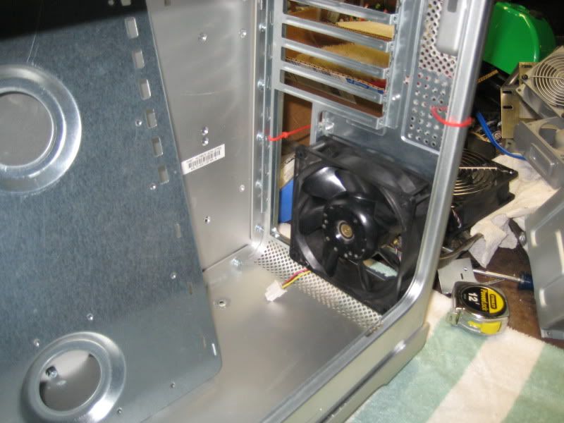
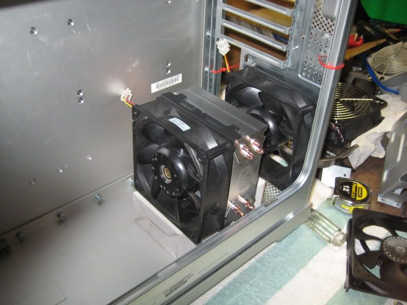
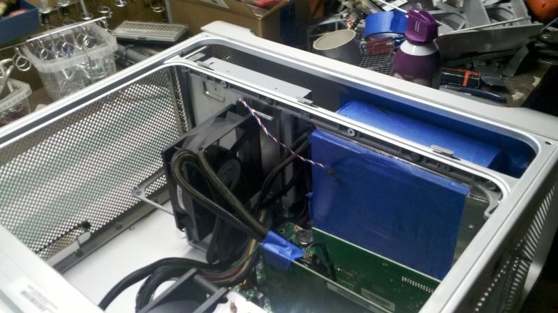
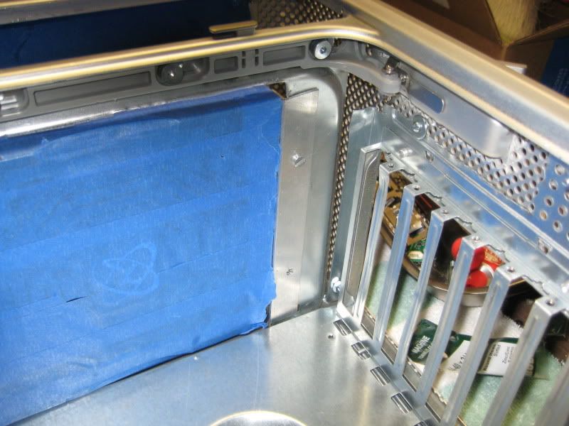
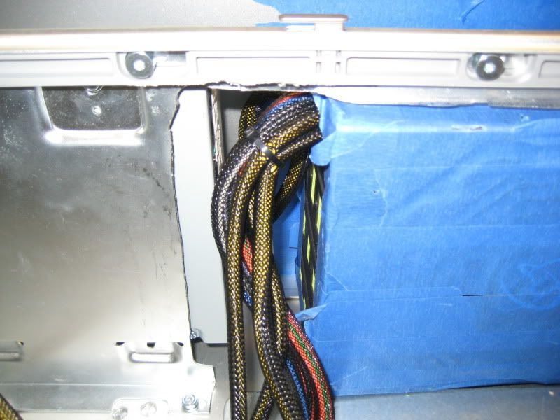
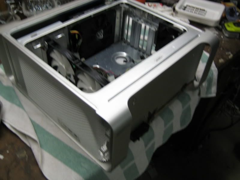
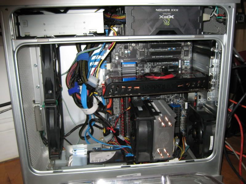
After removing the internals, I did a test fit of the ATX backplate (note that in these pictures, the case is upside down, so the ATX tray is in the "normal" mid-tower orientation, against the right side of the case. With the G5 case, as with some Silverstone and Lian Li cases, the mobo is against the left side of the case, and the right side panel is the one that opens. This, my CPU will be at the very bottom, with the video card above it, and the "ATI Radeon" writing on the side of the video card being upside-down. You can also see the "shelf" that is about 80% of the way up the case, at the very bottom of the pictures)
IMG_3768.jpg

IMG_3767.jpg


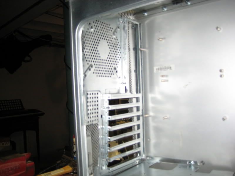
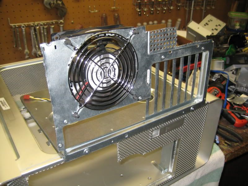
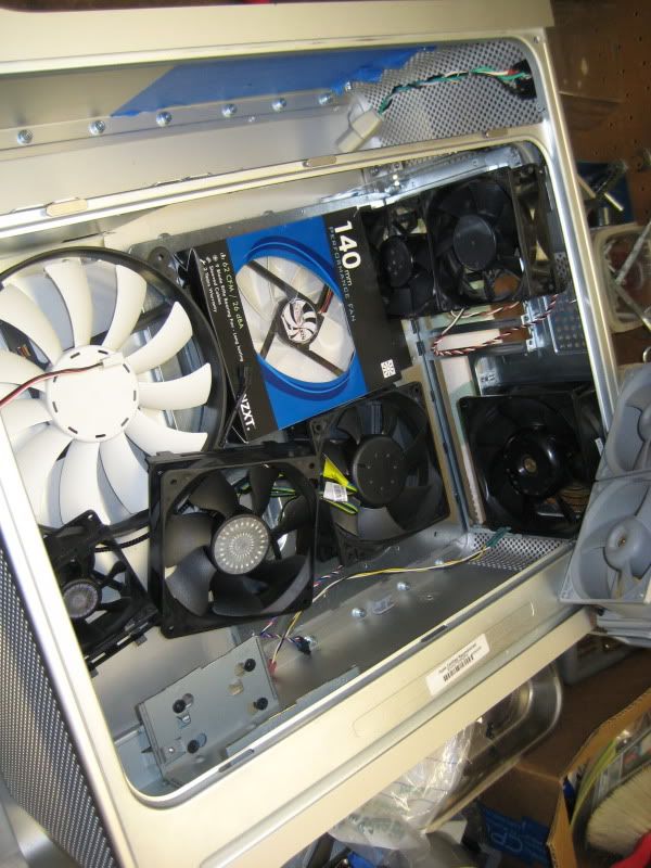
As you can see, it fits, but there's no room for a PSU between the mobo and the case floor like there is with the stock configuration. I'll need to find a new PSU mounting location. Additionally, take note of my fan configuration. some people completely remove the fans when doing a G5 conversion. Some re-use the dual 92mm fans that were part of the stock configuration, and some do a single or dual 80 or 92mm configuration on their ATX backplane (if they used a removable mobo tray from another case). I had never seen one with a 120mm rear exhaust fan, and I wanted to see if there was room for it.

Also note the lip running around the inside,. This is where the side-panel is seated, with a rubber seal. Cutting or damaging this would make the side-panel be unable to fit without cutting the inside of the side-panel, which I'll take a picture of tomorrow.
 
IMG_3784.jpg


Some more on this "shelf", the dastardly contraption that it is. It's that cross-bar about 80% of the way up the case. It's made of about 1mm thick steel. It's one tough son of a bitch to cut. The rest of the case is about 2mm thick aluminum, which cuts real smooth and easy. But the steel shelf is much stronger. I needed to cut it, and I had to cut it inside the case. It's only removable by unscrewing about 80 torx screws and fully disassembling the case into sheet metal, which I didn't want to do. That crossbar can't be cut out, because it has the nice latching mechanism. The side panel has a lip that rests in a groove near the bottom, and then indentations that latch onto the crossbar. The small lever at the back above the PCI slots is used to open and close the side panel. It's a real nice design, but it can't easily be taken apart.

I came up with a rough idea of what I wanted to do. At the very top of the case, at the back. I'd mount the PSU. I'd mount the ATX mobo tray below it, in the inverted CPU-down orientation. The dimensions neatly added up. In retrospect, it may have been wiser of me to keep the PSU at the bottom, but more on that later.

Clearly, I would need to cut a hole in the shelf in order to fit the PSU up there. That lip I told you about covers all of the corners, so I couldn't slide the PSU in from the side. It would have to come from the bottom.

At first, I wanted to keep the clear plastic air deflector, visible in one of the earlier pictures. It's a molded piece of clear plastic that fits in the side panel and does some ducting for the CPUs. It latches to the bottom of the shelf. I wanted to keep the latch intact.

Nibbling my way through the shelf (this was the most grueling part so far, took several hours, going 1/16" at a time, very sore hands for a few days)
IMG_3769.jpg

IMG_3771.jpg


IMG_3773.jpg

Unfortunately, the cutout I made was too small, and I had to remove the latch. I can probably still use the air deflector, since the side panel will hold it on, but this meant I needed to cut the shelf again.

Second cutout:
IMG_3775.jpg


Finally, this allowed the PSU to fit snugly. I'll secure the PSU with aluminum L-brackets later on. It's wrapped in blue tape to prevent scratches.

IMG_3776.jpg

IMG_3778.jpg
 
Here are most of the components
IMG_3780.jpg


For fans, I have some nice ones. I have a pair of Sanyo Denki "San Ace" 120x38mm fans that move 100cfm each. Supposedly they're the best fans around, and quite popular among watercoolers. Very good static pressure means they work well with heatsinks and radiators, and they undervolt well. I want a quiet build, so getting a nice 120x38 fan and undervolting it is a good idea. I plan to run one on my Hyper 212+, and the other as the 120mm rear exhaust.

I don't want or need a ton of fans. The huge mesh in front of the case means that I shouldn't need a ton of intake fans.

I want to run three - the two San Aces near the heatsink, and a third to blow air onto the video card and PSU.

The downside of my design was that the PSU intake is facing the GPU intake. They both have to fight over the same air. To alleviate this, I'm considering two options. I have a 120x38mm Delta fan that does 150cfm, and a 200x30mm NZXT fan that does 166cfm. The NZXT is quieter, but both are too loud for normal use. Again, I'll crank this fan up during gaming, and undervolt for normal use. I'll have to see if I can fit the 200mm fan, and if I can use the clear air deflector to improve performance with one fan or the other.

Shot of the rig as it's running now:
IMG_3781.jpg


I will be taking the HDD, SSD, and video card from this rig and moving them into the G5. Then, I'll move that rig into my Lian Li PC-7077B case for use as a HTPC. Specs as follows:
Xeon X3210 (quad core 2.13ghz Kentsfield)
4x1gb Wintec AmpX (there's that stupid letter "X" again) DDR2-800
Antec Neo Eco 620C power supply
Scythe Infinity heatsink
Sapphire Radeon HD 4650
IDE dvd burner to free up a SATA port
Zalman 32gb SSD
couple of 500gb WD drives for storage, add more drives and a SATA controller card eventually as storage needs grow.

It's in a heavy old steel Chieftec Dragon, with handles I added to make it less of a PITA to move around.

Anyway, back onto the G5

Luckily, they use a standard DVD-ROM, which should fit. There's a nifty little door that moves up and down.
IMG_3789.jpg


Imagine the Hyper 212+ with the stock fan (I forgot to take a picture). Wimpy wimpy wimpy! Now with the San Ace. Hefty hefty hefty!
IMG_3790.jpg


The back, after some more cutting
IMG_3787.jpg


It fits. It actually fits. To my knowledge, I am the only person to have a G5 case with a 120mm rear exhaust fan. It's a tight squeeze, though. Top of the fan is touching the lip around the case, but the side panel still fits on.
IMG_3788.jpg


Lots of cooling potential if I get a K-series Sandy Bridge and overclock
IMG_3793.jpg


You gawt a purdy mawth, boy. Cut out the nasty perforated steel fan grille and replaced it with a nice less-restrictive wire one. Used rubber anti-vibration mounts.
IMG_3796.jpg


Side panel still fits on. It touches the 120mm fan, but it fits.
IMG_3799.jpg


Next order of business was the hard drives. I cut out the hard drive rack to make room for the PSU.

This is where the shortcomings start to pile up for the G5 case. It's all sheet aluminum, but that means that things are very hard to mount. It's not like a normal case that has a metal skeleton with thin panels. The G5 has thick panels that support themselves. If I wanted to screw something into the aluminum, it would go through the case and out the left side. This, the only places I could actually screw things into the case are the shelf, the back panel, and the bottom, where the holes won't be visible. Additionally, the left side is not removable.

Normally, there's two ways to handle drive mounting. You can make a fixed drive cage part of the case. You need to make both sides removable, so you can screw in both sides of the drives. Otherwise, if you want to make one side not removable, you put the hard drives in a removable rack so that they can be screwed in outside of the case, then snapped in.

The G5 had nice side-mounted ones that slid into the top, but I removed that in order to fit a full-ATX mobo. I wasn't sure where or how to mount the hard drives, and even seriously considered ditching the optical drive or the mechanical hard drive, as my 120gb SSD is plenty even for games.

From the dragon case my rig is currently in, I pulled one of the 3.5" drive cages. It fit four drives, and had the nice rubber grommets to prevent vibration. Since it was way too big, and I didn't want it obstructing airflow or hitting my video card, I nibbled the top half off.
IMG_3800.jpg


You can see two pieces in that picture. The left piece is the bracket for the case that holds it. Three tabs slide in the bottom, then a screw in the far side holds the cage in place. The right piece is the cage itself.

What I elected to do was mount this in the very bottom of the case. Remember, there's a radius on the corners, so there's about an inch of clearance between the edge of the mobo tray and the bottom of the case. I bolted the bracket to the bottom of the case, so that the top rear edge of the hard drives was near the front bottom edge of the mobo. This way, I can remove the rack with a single thumbscrew (which is very awkwardly placed on the far side of the bracket, such that you can't see it and have to do it by feel.

After almost two week's work, here is where I am (with my P4 mock-up system)

The bottom, featuring the hard drive rack
2010-12-31_02-40-55_702.jpg


The top, featuring the PSU
2010-12-31_02-41-18_16.jpg


It's a much cozier fit than anticipated. I have a whole bunch of unused space between the front edge of the mobo tray and the front of the case, but everywhere else is cramped. Additionally, I discovered today that the PSU cannot be removed with a mobo installed. If I need to swap it out, I need to remove the mobo as well as half of the standoffs, so it can swing out over the mobo tray. So much for my brilliant plan. I'd have been better off mounting the PSU at the bottom of the case, and moving the ATX tray upwards, so that the last PCI slot was at the very top. That's part of the impetus of making this log (I was going to wait until I was almost finished). I need some advice.

What I need to do:
I need to make a fan controller. I have no front drive bays to install an off-the-shelf one. I don't have many fans, either. One channel is fine. I have a design that uses a LM350 voltage regulator that should be capable of 1-channel, 36-watts. I ordered the parts and am waiting for them to arrive. I got a nice aluminum knob, and plan to mount it somewhere on the front or top of the case, with only the knob visible, and the circuit board hidden somewhere inside. It uses a LM350, a 100 ohm resistor, and a 5k pot to theoretically adjust from 1.25v to 12v.

I need to figure out the pinout of the front panel headers. Getting the power button and LED to work are essential. Getting the USB to work would be nice. I don't care about firewire, and depending on the size of my fan controller knob, may try to replace the firewire port with the fan controller knob. I've seen a few pinouts online, but need to confirm them (some say there are issues with firewire pins being shared with power switch pins)

I need to epoxy in the mobo tray. The backplate is firmly attached to the rear of the case, but the tray itself is just wobbling, and there's no way to screw it into the aluminum side panel. I need to mount in the P4 mobo and get it lined up, and then I can epoxy it in.

I need to determine a solution for the DVD eject button. it's not accessible from the front of the case. The large mechanism for the tray door blocks the eject button. I am considering opening up the drive and soldering a second eject switch. Then, I would mount the switch discreetly. Ideally, it would be inside the case, and then a thin metal rod sized to fit in one of the circles in the front mesh would be mounted so that it stuck out a millimeter or so from the mesh, very discreet, but could be pushed to open the drive. Not my first priority, as I will only need to open the drive to install Windows, and I can do that with the side panel off so I can reach the drive.

I need to figure out my PSU location. I liked the design I came up with, but I'm nervous about the fact that it will fight with the video card for air, and that it can't be removed without first removing the mobo (which in turn most likely can't be removed without removing the heatsink).

I might have better luck moving the mobo tray up to the top, and mounting the PSU by the CPU, perhaps even having the fan face downward and cutting ventilation holes in the bottom of the case (I'm not worried about how it looks). Of course, that will likely cause problems with something else, although I'm not sure what. I might have issues with the GPU hitting the DVD drive, I'll have to measure.

At this point, I'm open to entertain any comments or criticisms on what I've completed so far, and look forward to some advice on how to figure out the fan controller, eject switch, front panel connections, PSU location.

Also, any suggestions for a title?

I was thinking Bad Apple, like "a few bad apples ruin it for the rest of us". Then I was thinking I could paint it black and call it "Black Macgic", but I'm not a good enough painter to feel comfortable painting it. It's got this nice texture, anodized or powdercoated or something I'm not sure, and I don't want to have paint issues. I was also thinking of a pun with "PowerMac i5" since I'm leaning towards the i5-2500K atm. But those are somewhat lame, I fear.
 
At this point, most of the big structural stuff is complete, and I'm getting into the nitty gritty of making the wiring work.

I shouldn't have been surprised at how difficult this is becoming. I'm maintaining a decent standard of workmanship, and this is a very time consuming project. It appears at first glance to be just moving a mobo tray around, but things have a way of becoming more complicated then they seem.

First, a shot of my really ghetto hex key. This has to reach down between two 7" deep heatsinks to undo some bolts, and it worked. It's a long flathead screwdriver with a 2.5mm hex duct taped and zip tied to the end.

IMG_3806.jpg


Some shots of how tight PSU clearance is. It will fit, though. PSU is against the roof of the case, and as far back as I can go without hitting the ~1" radius edge fillet.
IMG_3807.jpg

IMG_3808.jpg


Mail arrived from Amazon, contains a NZXT individually sleeved 8-pin mobo extension, so that it will reach from the top of the case to the very bottom edge. At this point, I've narrowed down my Sandy Bridge mobo requirements to "has 8-pin connector" so that I can use this bad boy. Overall, though, I'm still not much of a fan of individually sleeved cables. I like the all-black flat cables like some Corsair PSUs have. I like the cables that are braided inside a clear round jacket a lot. I would really like to see something like a mobo connector where all the wires are black, so you don't see the rainbow leading into the sleeving, and through the sleeving. But individually sleeved just doesn't appeal to me.

Envelope from All Electronics for some wiring arrived, as well.
IMG_3809.jpg


First on the docket was the power plug. Because of the edge fillet, the PSU sits about an inch or two from the rear of the case, meaning the plug can't be accessed. I wanted a proper panel mounted IEC connector, so I chose to butcher an IEC cable and buy a male socket.

Nibbled the hole
IMG_3825.jpg


Installed. I braid whenever I have three wires. I also had to cut off most of the strain relief boot on the end of the plug, so that it could bend properly.
IMG_3830.jpg


Trying to figure out my fan situation:
IMG_3832.jpg


1. NZXT 200mm fan.
Pros: 167cfm, 36db - moves the most air
Cons: Will require modification to the plastic air guard to fit (fan is slightly too wide for the case)

2. Delta 120mm fan
Pros: 150cfm, second most amount of air. Fits easily
Cons: Loud as a jet engine

3. Apple 92mm fans
Pros: Has a nice shroud that I could re-use
Cons: Can't figure out the damn wiring

4. CM 80mm fans
Pros: Not a PITA to install
Cons: Poor airflow/noise performance

5. CM 120mm fan
Pros: easy to install, quieter than Delta
Cons: low airflow

6. Dual 92mm fans (JMC Datech and Nidec Beta V)
Pros: Would fit in nice apple shroud, and I already know the pinouts
Cons: Spin in opposite directions, both have temperature sensors which are a drawback for intake fans as it keeps the speeds low no matter what, one has good airflow and the other has okay airflow once the sensors are bypassed

7. NZXT 140mm fans (one or two of them)
Pros: 70cfm, 26db, can fit two in the front of the case
Cons: Not sure

8. Another fan option (Maybe a silverstone air penetrator, would be perfect, but expensive - the first 7 options are all free or already acquired)

Right now, leaning towards the NZXT 1x200 or 2x140. However, I need some advice on placement. I want an air intake that directs air to the top of the case. I have the PSU fan and the GPU fan intaking from the same area, a narrow plenum formed by the mobo, PSU, GPU, and side panel. I ideally need something that will direct enough air for my HD 5850 (80mm fan) and my PSU (135mm fan) above the GPU.

I figure that the front of the case is open enough that the CPU HSF really doesn't need any airflow from the front of the case, as it's already an overkill fan setup. So something like running two front intake fans wouldn't be as good as, say, running a single more powerful fan blowing across the top of the GPU. The only reason I considered 92mm fans was that two of them can fit side by side, and both blow on the GPU.
 
I also assembled my LM350 fan controller.

It uses a LM350 adjustable voltage regulator, rated for 3amps (so 36 watts per channel, 1 channel)

Had a boatload of problems with it, until I noticed that they sent me 100k ohm resistors, not 100 ohm resistors. The 100k ohms were so high that the controller didn't work, but I had some 150 ohm resistors hanging around, and fixed it with one of those.

It uses a 150 ohm resistor and a 1k linear pot to adjust voltage. Have been having multimeter oddities so I couldn't measure the range exactly, but it's enough to bring the fans to a complete stop and to full speed.

I wanted a single channel setup so that I could have one knob for the whole thing, and not have to make four cutouts on the front of my purty case. Only options seemed to be getting a 4-channel high wattage one and only using 1 of the channels, or DIY.

I have a few major concerns with this, though.

I think (but I'm not sure) that the heatsink I'm using to cool the LM350 is hot (electrically). I have to measure it and double check the datasheet, but I think it's at whatever voltage my fan output is at. This is not a good thing at all, as it could short out to the case.

The fans can be brought to a dead stop by it. At first, this sounds cool, but in practice I wouldn't like a knob on the front to be able to make my PC overheat. Would have preferred a ~5v minimum setting like most fan controllers.

During testing, I burned the potentiometer. Smoke came out, and a few seconds later there was an orange glow from inside. Then, it worked normally, and has been working normally since then. This worries me, as I don't know what happened, and I don't know why burning it up inside didn't break it.

IMG_3837.jpg
 
After some thought, I am very hesitant to use that fan controller, for the reasons above. I would hate for someone to brush against it and turn the fans off, or for the possibly live heatsink to short out against the case, or another disaster. The potentiometer did smoke and burn a little when I turned it on, not sure why.

After some reflection on the fan situation, the Delta 120mm is just too loud. I will instead go with the two NAXT 140mm fans, I think. Side by side, they have 70cfm each at 27db, and can mount easily, without cutting the clear air deflector. They move similar air at a lower noise level to the Delta (150cfm vs 2x70cfm). I'm sure I'm losing a significant amount of static pressure, but they're not up against a heatsink or anything that would be cause a problem.

I tackled the DVD-RW situation. Apple uses a standard optical drive mounting, and has a really nice door that slides down when the drive opens using a very nifty little spring mechanism. Unfortunately, there's a problem (of course). Apple has a keyboard button to open the drive, so there isn't one on the front of the case. Because of this large door mechanism, there's no way to ghetto mod one either (initial thought was to take a thin metal tube that fits inside one of the mesh holes, and glue it to the button so that it only sticks out an eighth inch or so from the front of the case and is very discreet, but the door mechanism completely blocks off the front of the drive.

To remedy this, I opened up the drive and soldered a nice external eject button. Since I don't want to ruin this cases good looks, I mounted it on the back. I will likely use that drive to install windows, and then never use another CD in it again, but it's nice to have and a rear-mounted button is very discreet.

The button:
IMG_3839.jpg


PSU unmasked (no, it's not really made of blue tape)
IMG_3838.jpg


Mock-up views:
IMG_3841.jpg

IMG_3843.jpg

IMG_3844.jpg


Clearance is cozy, to say the least, with the exception of the gaping open area in front of the case. This will be well utilized though, giving me room to run the cables, and allow me to mount the fans a few inches behind the mesh so they are less restricted and harder to see.

Next up on the docket is figuring the pin-out of the front panel connectors. It uses a single connector for firewire, USB, power switch, and power indicator. I have a diagram of it, but I'll have to do some soldering to put on the regular mobo front panel headers. Other than that, the last big thing is mounting the fans. I had a genius idea for wire management. Wire management is so easy in most cases, with room between the mobo tray and the back of the case. I don't have that luxury, so there's nowhere for them to hide. I plan on using those square sticky pads with the zipties that a lot of OEMs use, but with a twist. Instead of zip tieing the cables themselves, I'll use the zip tie to affix a velcro cable strap. This way, I get neat wire management, but it's easy to move them around if I have to.
 
Late suggestion... What didnt you mount the psu in the front at the bottom and leave the HDD bays intact? then just run a kettle extension from the back panel into it. Like on the Lian-Li A05.
 
That was my original idea, but there wasn't enough room to fit the PSU on the bottom in the front. The RAM slots would get in the way. I love the A05 design and that was my initial plan, but the A05 is a couple inches deeper, so the PSU can clear the RAM slots.
 
Interesting idea I hope it turns out well. Can't wait to see more of your progress.
 
I'm liking it! I love seeing all the mods. It makes me wish I had done a few things differently with mine.

I look forward to seeing the end result.
 
Mounting the front fans now. Decided to use the two NZXT 140mm fans. I will mount them from below the DVD drive. I'll make a L-bracket under the shelf.

Nibbled out the L-bracket. I've gotten pretty fancy with the nibbler by now.
IMG_3846.jpg


The fans:
IMG_3847.jpg


Also got this little thing. It's a remote controlled molex connector. I'll use it to control some LED strips I mounted to the back of my monitors, mounted outside of the case.
IMG_3849.jpg


I made the front panel connector. Wired up USB, power switch, and power LED. The USB was semi-working - USB devices seemed to have power, but wouldn't connect. The LED doesn't want to light up, but the power switch is working perfectly, so the pinout diagram I was using was correct. Gotta play with it a bit more, and clean it up.

IMG_3851.jpg


Case put together. On the bottom, I have mounted a Gelid fan controller (it's their version of a Fan Mate). I have it running the two San Aces. They're both something like 6.3W, and the controller is rated for 12w.
IMG_3852.jpg

IMG_3854.jpg

IMG_3860.jpg


I built my SB in it:
Intel i5-2500K
Gigabyte P67A-UD4
2x4gb Ripjaws DDR3-1333
XFX HD 5850
CM Hyper 212+ with two San Ace fans
120gb X-25M
500gb WD Blue
XFX 650w PSU
DVD-RW

IMG_3868.jpg

IMG_3866.jpg


Gonna get some red SATA cables and clean up the wiring.

Tight clearance between the RAM and CPU fan
IMG_3872.jpg


Only major issue right now is the fans. The Gelid thing must be over-rated. They start off slow but ramp up in speed. The fan controller is hot to the touch, so I think they are drawing more current than it can handle. I ordered a Sunbeam rheobus rated at 20 watts per channel, hopefully that will work better. It's a 5.25" bay mount, but I'll probably put it somewhere in the case and just set the fans to a medium-low setting.
 
nice job. I love the Mac Pro and Power Mac cases. I have grown out of the crazy LED, huge window type case and now the only ones I really like are the simple and functional cases.
 
No, you're not the first with a 120mm exhaust on a G5, but I love what you've done. You've also answered my question about whether or not a PSU can fit up top there. =]
 
Back
Top