iDuplex - Prodigy on the Rampage

MrBean_Oz

Limp Gawd
Joined
Jul 7, 2006
Messages
366
As some of you may remember, a while ago I started a project worklog, named iProdigy. This was going to serve as a small, yet powerful gaming/everyday monster for my iWife :)

Well, the system is doing really well, I gave it a few weeks burn-in on the online racing simulator, iRacing, where it performed exceptionally well, driving the 30" display at full game settings, with a single GTX 670. You can see more from the link in my signature.

Well, the PC has finally found its berth on her Desk in the study, so I need a new iRacing monster.

Thus starts project iDuplex.

What should it be capable of?
A monster gaming rig, running 8-12 hour iRacing sessions, while driving triple 30" at 2560x1600 res, full graphics settings.

Needs to perform this in the finicky climes of Melbourne Australia, where summer temps can sometimes approach/exceed 43-45 deg C.

Platform
Micro-ATX, all watercooled

Hardware- already in my hands
Asus Rampage Gene IV MATX motherboard
Intel 3930k Processor
4x 4GB Samsung Slimline low-voltage Dimms (yes, them ones!)
2x MSI 680GTX Lightning cards

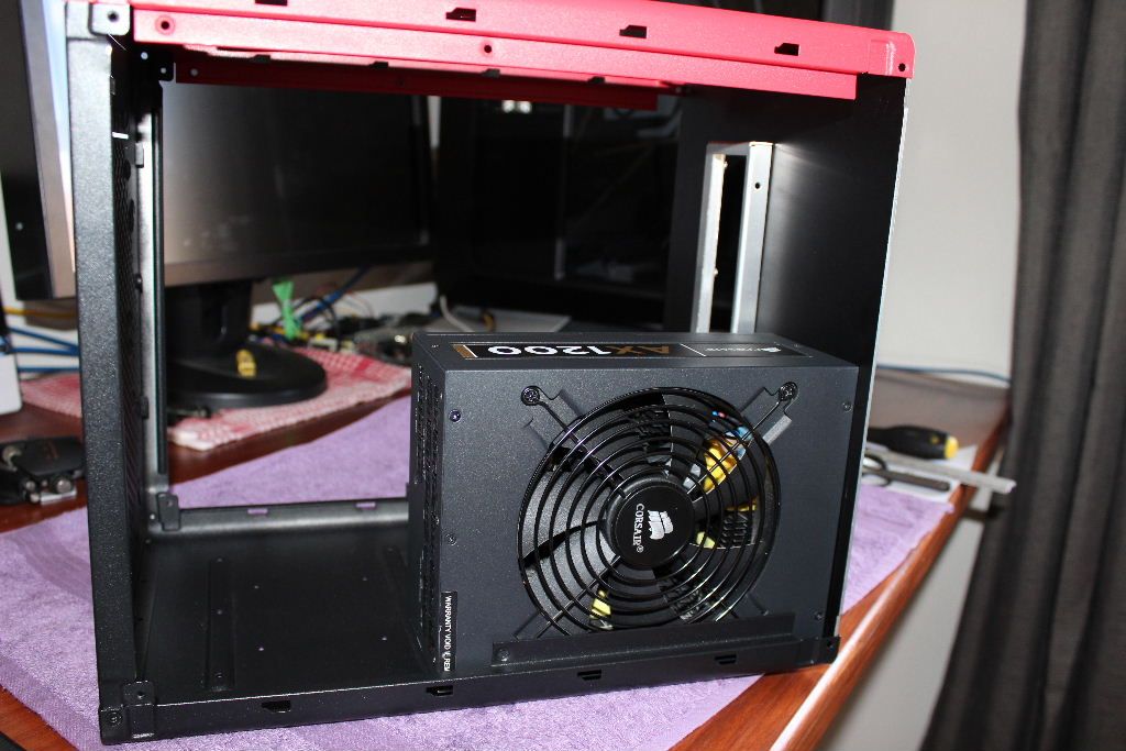
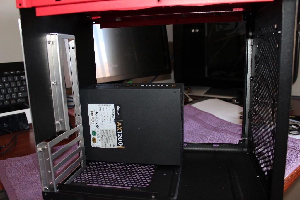
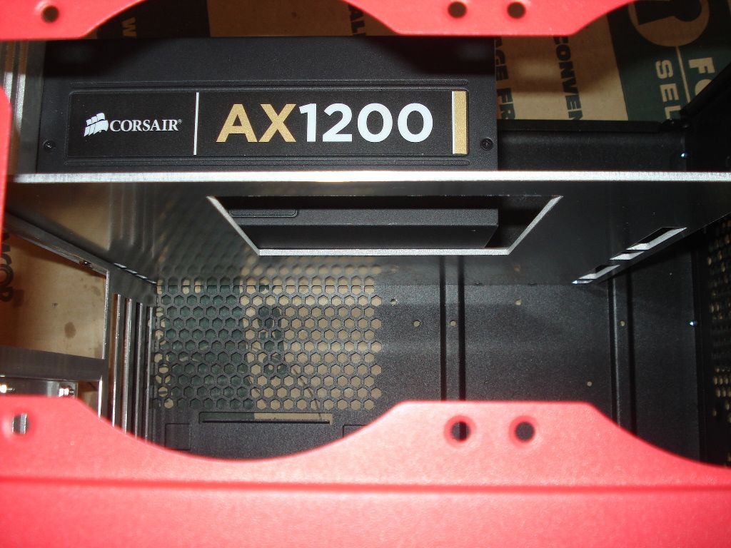
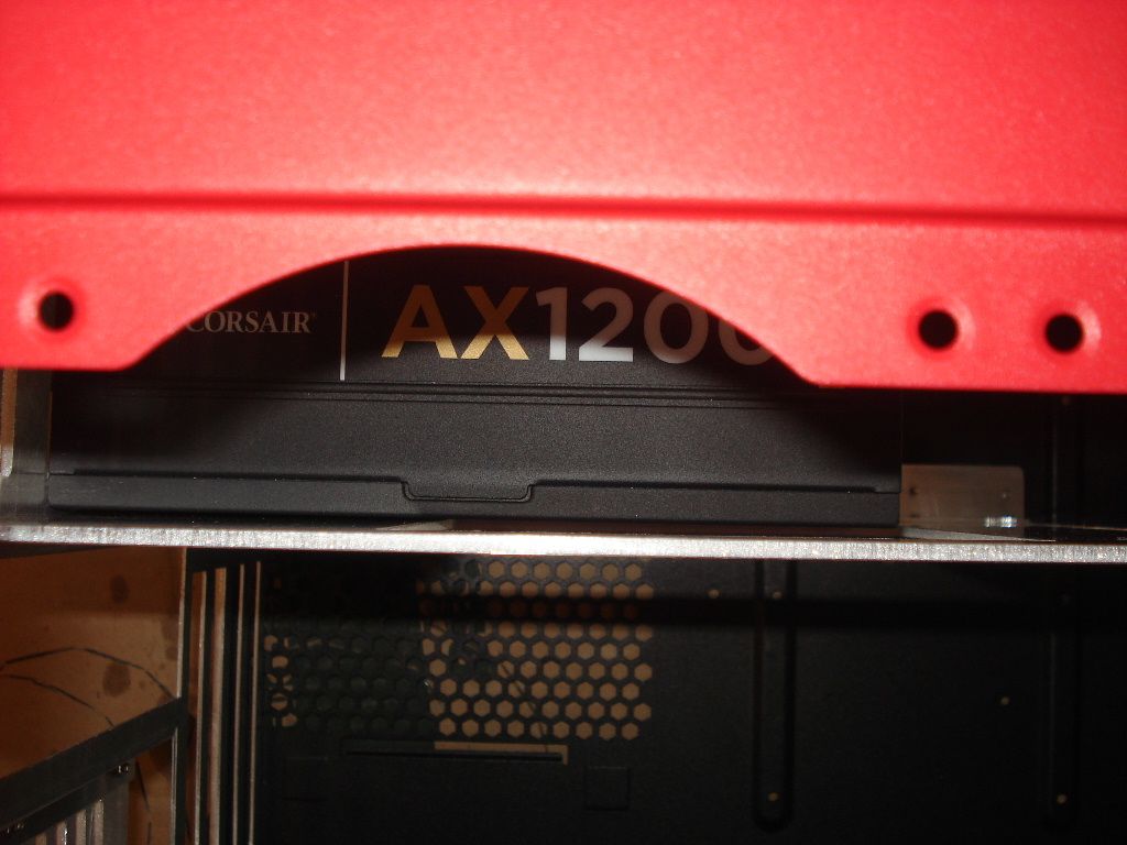
1x Corsair AX1200 (overkill, but no one wanted to swop for a Seasonic 860 Plat)

2x 256GB SSD Drives

1x Alphacool 280mm UT60 Rad
1x ApogeeDrive II for Socket 2011
1x Aquacomputer 680 GTX Waterblock (need a 2nd one, ordered)
1x Aquaero 5 Pro, temp and flow sensors

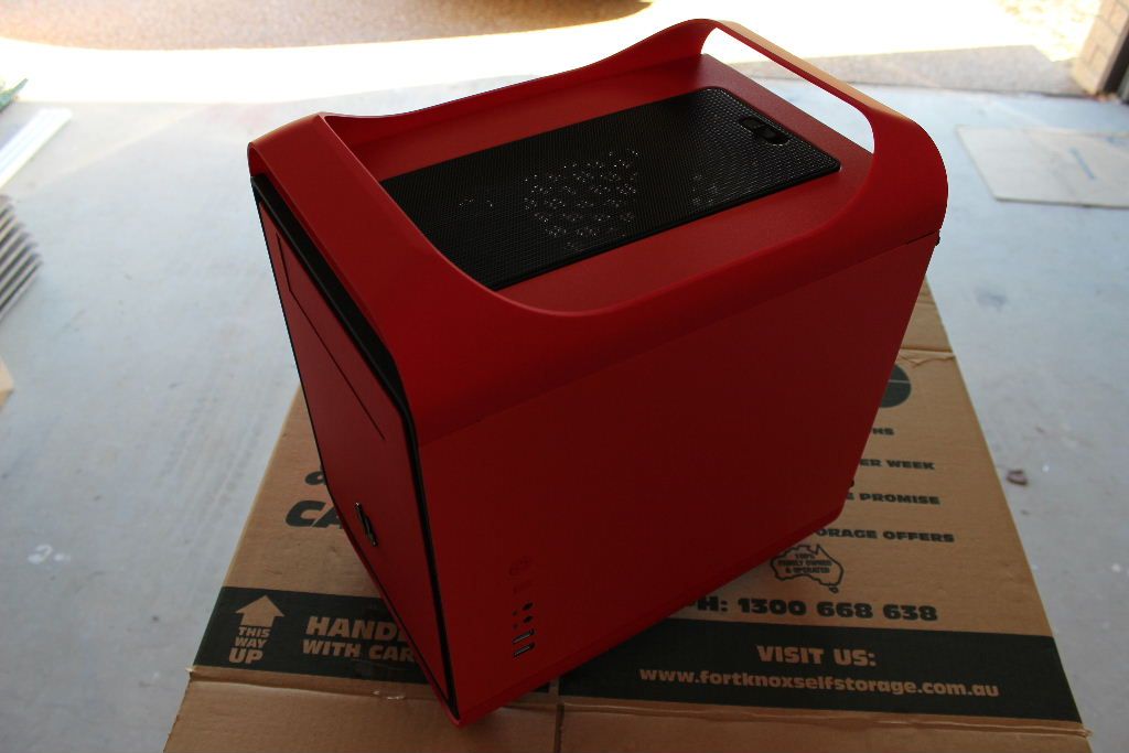
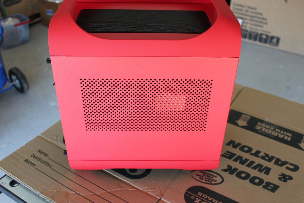
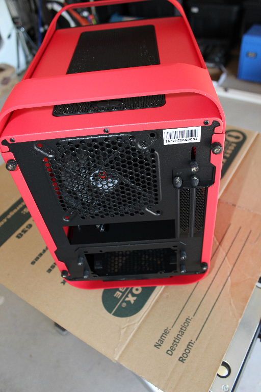
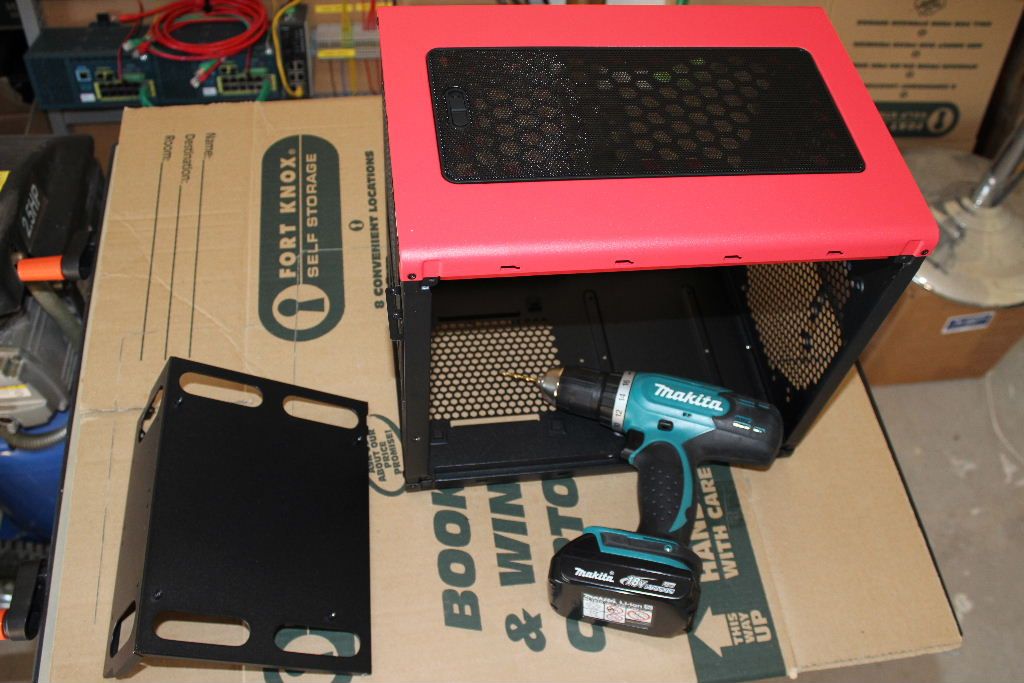
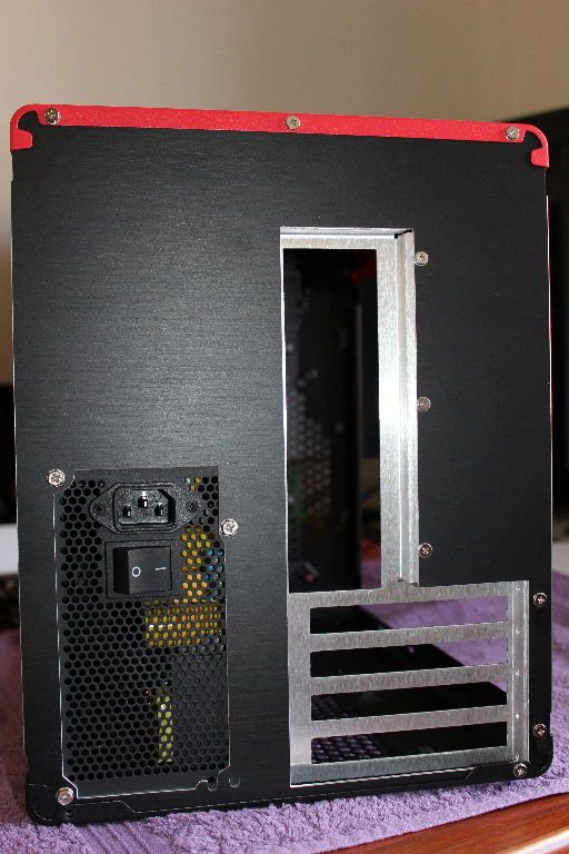
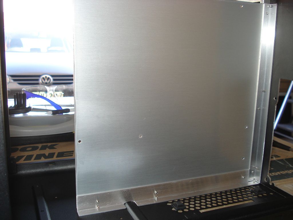
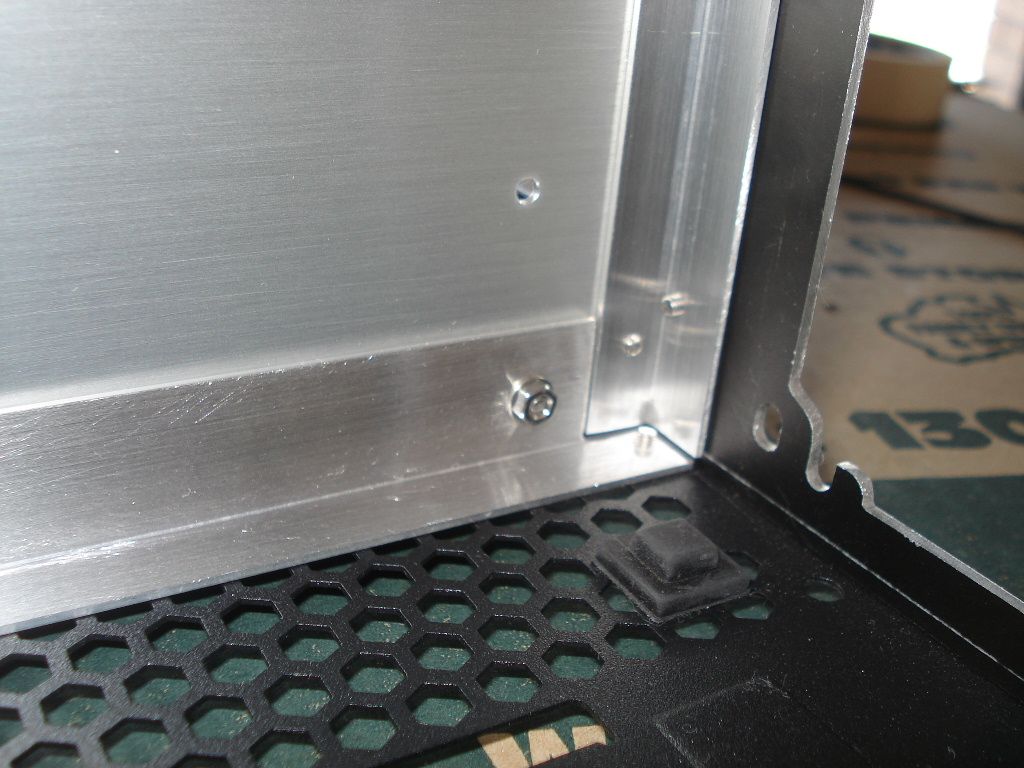
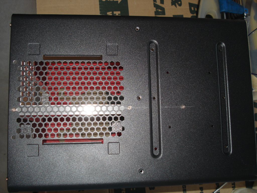
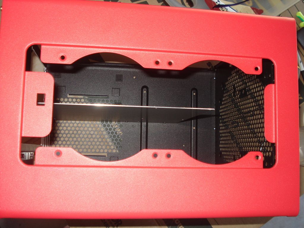
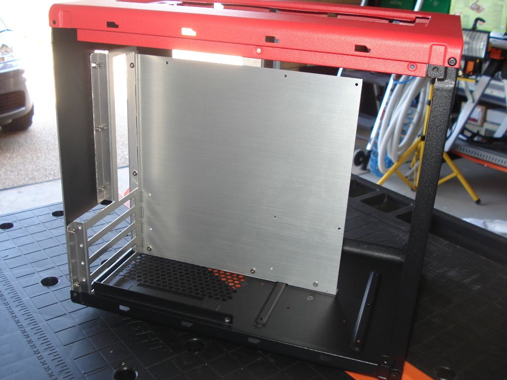
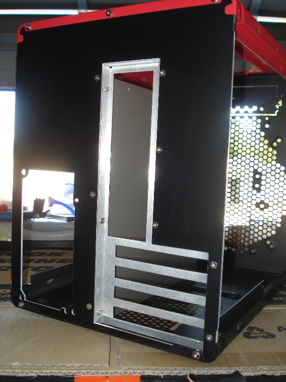
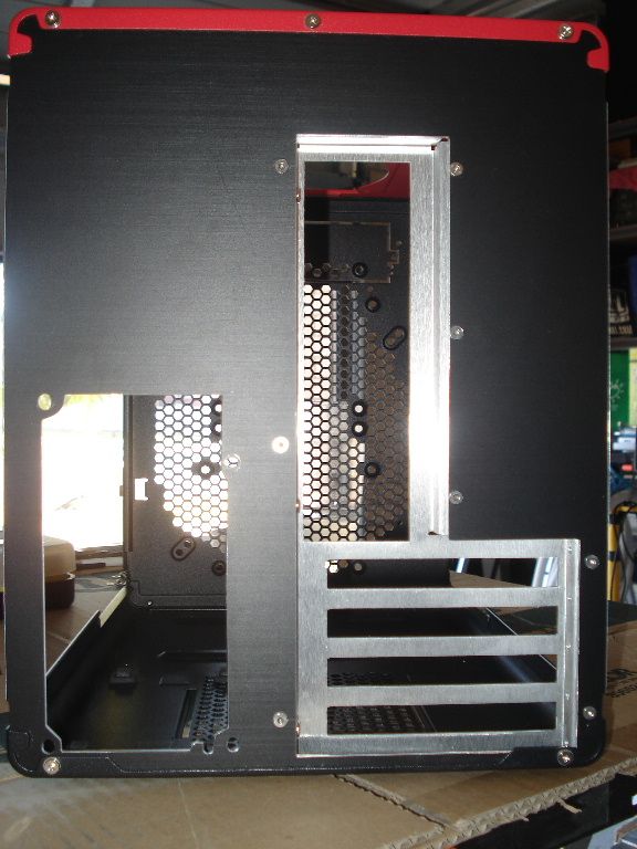
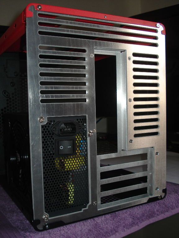
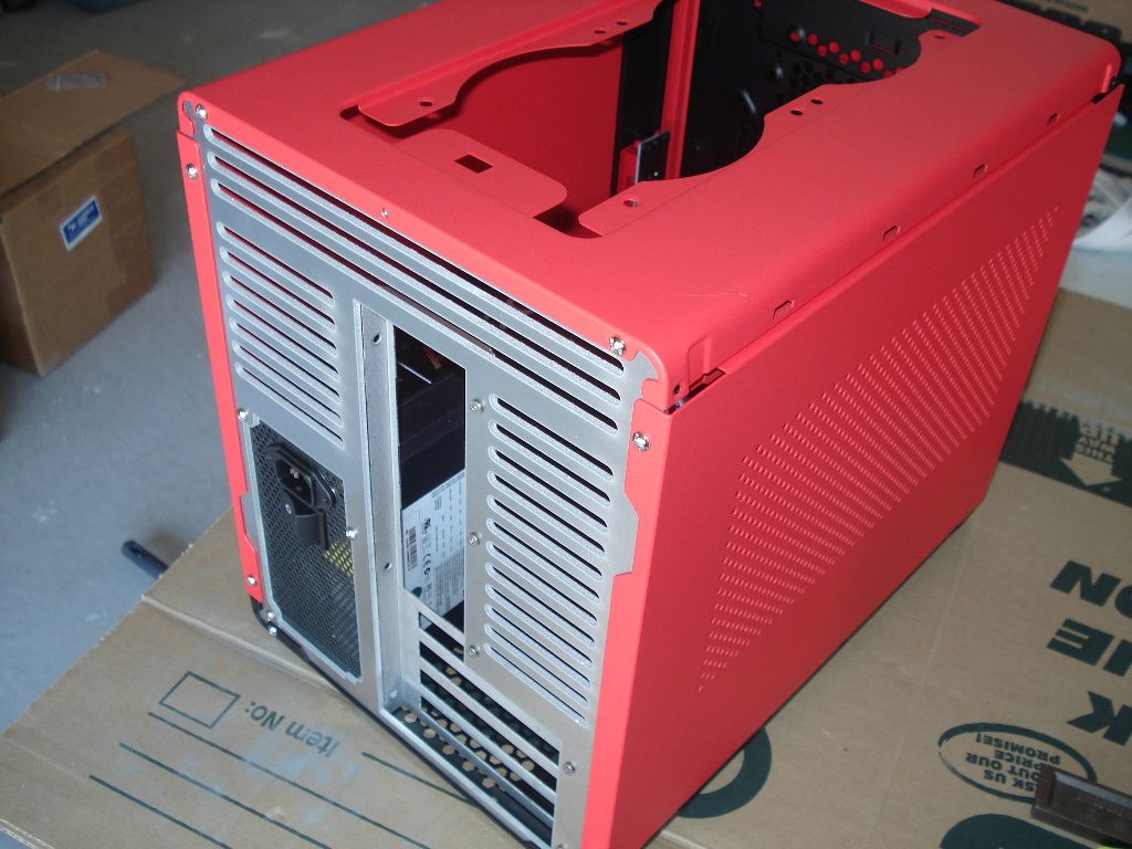
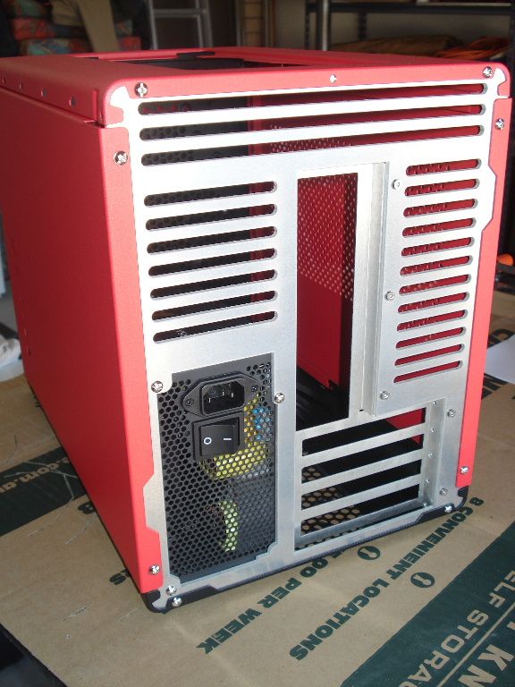
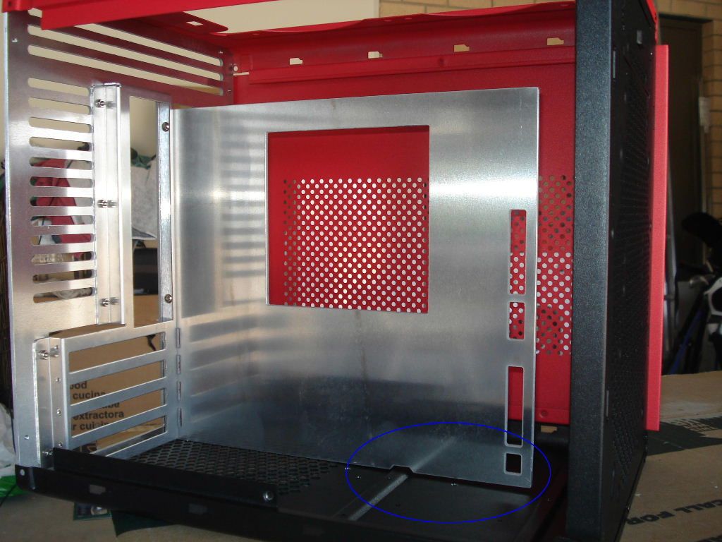
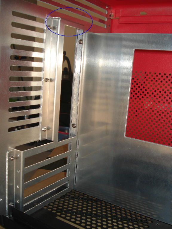
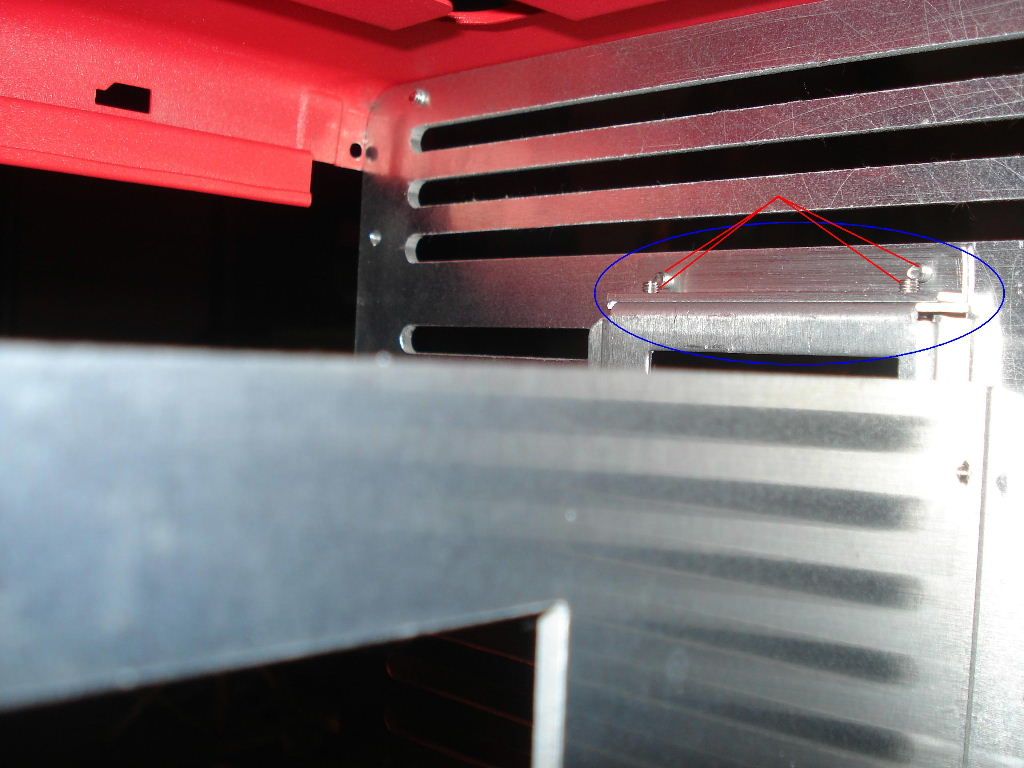
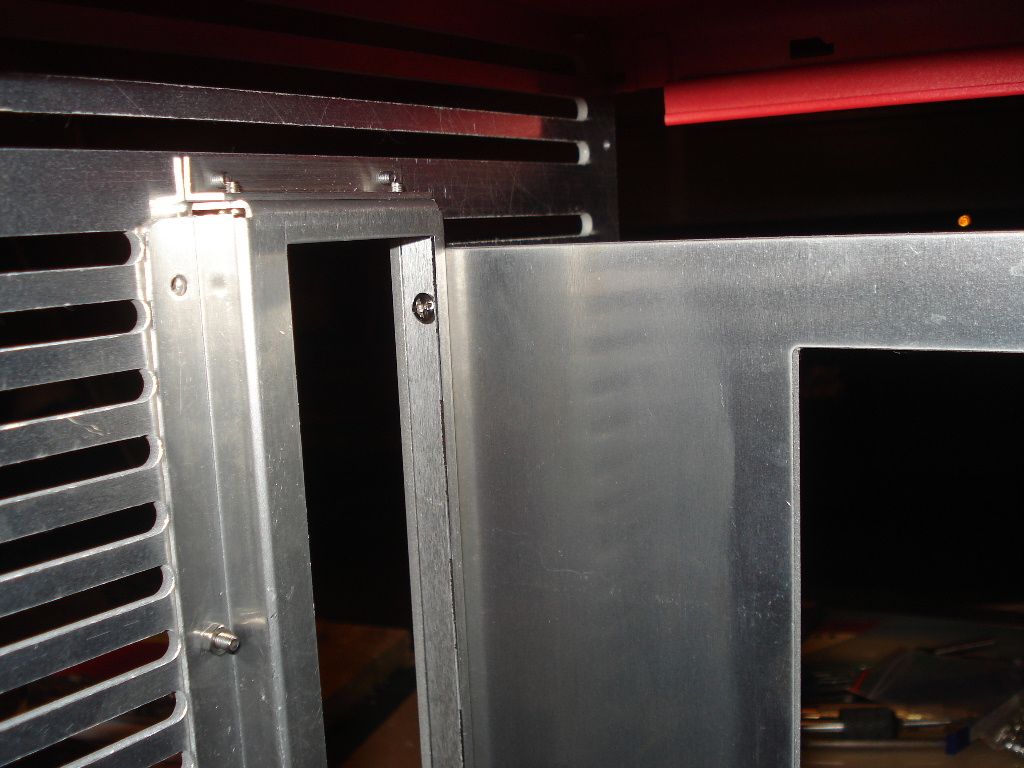
1x Red Prodigy mini-ITX case (wtf, Beano, you have a micro-ATX motherboard, idiot, case is mini-ITX?)
1x Dangerden micro-ATX rear port plate (ah, I see what you did just then)

Hardware - on order
1x Aquacomputer 680 GTX Lightning Waterblock - ETA 13 Feb 2013)
 
The Prodigy being a mini-ITX case, could have complicated matters, but, due to the rather volumous capacity of it, being similar in volume to many micro-ATX cases, I thought it might be pretty simple to convert it for MATX use.

edit: For the Boyz over at Bitfenix - this ain't red, it's a mix between red and pink, fwiw.

The standard required photos of the victim in it's pure, unaltered innocence - never will it be the same.

3.jpg


2.jpg


and the back, where the biggest changes will happen

1.jpg
 
Of course, for what I am planning, nothing on the inside will remain, it will be totally custom - so out with it!

4.jpg


All handled by my trusty old Makita 18V cordless...

5.jpg


Usually with my build logs, I would do a step-by-step of the process, from measurements to final product, but this takes to much time, and effort, so I will skip those mundane steps.

Here is a shot with the backplate in early stage of completion, with the AX1200 PSU fitted to see how it will sit and if any modifications are needed - generally I wouldn't expect any issues, as I plan things pretty thoroughly in my head beforehand, and I do take a few measurements, and go from there.

6.jpg


In the next pic, you can also see the Dangerden IO plate I ordered from Greig at Gammmods - I am sure this was the last one, and with DD having closed down, well, the next best would be a Lian-Li unit, with integrated motherboard tray - which I did not want for various reasons, which will become clear later on.

8.jpg


and the back side, not to shabby. All this done with a jig-saw, and a variety of hand files - no milling, no CNC. Did basic handtools as part of my Instrumentation Certification back in the mid 80's....so, pretty old school, hehe....

7.jpg
 
We cannot have the motherboard tray dangle loose inside the case, so I fabbed a few brackets for it, which provide a very sturdy anchor - Adamski over at Overclock.net might want to do something similar.

10.jpg


upon closer inspection, I need to trim the vertical one down, even though it would hardly be visible, sitting behind a monstrous 1200W PSU, well, this bothers me, see circled area...

9.jpg


Also here you can see what I've done to clear the one mounting point for the priginal HD cage....pardon the finish, pretty rough, and will get the treatment...

11.jpg


and a couple more from different angles...here I have taken some sandpaper to them, and also trimmed the excess 'overhang' down....

12.jpg


13.jpg


A close-up of the vertical trimmed down, no 'overhang' here....

14.jpg
 
Here is a shot from the bottom, with the rail being secured by 3x 3mm screws- both the bottom and vertical motherboard retention rails have been drilled and tapped for 3mm screws, makes life easy should you want to do future work/mods.

I hate poprivets with a passion!

15.jpg


and, a top-view, pretty much smack bang in the center :) This allows enough space for the motherboard and cards, as well as giving ample room at the reverse side for the PSU, with room to spare..

16.jpg


and a view from the motherboard side - please note how close the motherboard tray is to the bottom, it was done for a very good reason, which will become clear a bit later in the exercise.

This was also why I opted for the DD IO-port plate, as opposed to the Lian-Li one, which came with a mounted tray - I fabbed this one from 1mm aluminium, and is down to the exact mm to give clearance above...which is needed...for...something...special....

19.jpg


and for now, a final 2 shots from behind, with the backplate drilled and countersunked - came out pretty neat, all done by hand/manual labour....blah...

17.jpg


and

18.jpg


Enjoy, next steps would be to tap the motherboard plate to accept 6.5mm stand-offs - fortunately I have exactly 8 of them, what a relief... Motherboard tray is drilled already, just need to tap.
 
A Small update: Jeesh, I luv the postie, just dropped of my last bit of hardware, the second Aquaero WB for the 680, as well as the pretty decent SLI bridge to join the 2 blocks.

Also, the backplate in the earlier photos was only a prototype, alowing me to finetune a few settings, before finalising the AutoCAD drawing.

Anyway, here it is, not as spectacular as others out there, but then again, most of you know me as a very practical person, this would do a great job for its intended application. I am not really a 'bling' person, hehe :tongue:

This was exported to png, it came rather well, and I should have the real version very soon... exellent, pics to follow. It will be cut from 3mm aluminium, will be nice and sturdy.

BackplateResizedRender.png
 
From the dxf above to this......came pretty nice, 3mm thick, should be the final version....

DSC04461.jpg


A Few pics of the plate being fitted....

DSC04463.jpg


Here you can see how the whole shebang was moved a couple cm's towards the PSU side, to make way for the GFX watercooling...not so much in the center anymore.....

DSC04472.jpg


From the motherboard side, came out rather nice and clean...

DSC04475.jpg


and finally, with the PSU fitted, just checking to make sure all is well....great, good progress for the day...

DSC04474.jpg


and
DSC04477.jpg
 
I wish they would make a mATX option for this case. Then again, if they did that there wouldn't be any cool mods like this one. Very nice work.
 
That new back plate looks pretty bitchin'. Interesting color as well, subbed.
 
Love it, I have a prodigy sitting around waiting for the mATX modification but I didn't know where to start! Your build will definitely help me alot
 
Thanx for comments, and looking, as always, appreciative!

Just a few progress pics, this is coming together nicely, amazing how much one can achieve in a couple of hours here and there :)

For some reason, I quite luv these two shots.....

2_DSC04495.jpg


and

1_DSC04494.jpg


anyway, been having a go at fitting my finished motherboard tray, cut from the same 3mm aluminium on a CNC Waterjet - again, I could have done this all by hand, but I am running against time here....pretty busy professional life, iRacing, et al, so little time for modding...

With the tray fitted and perpendicular to the back, I notice the case was off by a couple of mm....

3_DSC04498.jpg


Ah well, nothing a few screws can't fix, bend the case back in shape, and attached them, all good and square...

4_DSC04499.jpg


and

6_DSC04507.jpg


and

7_DSC04509.jpg
 
From the back, it looks like this - please note screws will be shortened , this is just test fitting :)

10_DSC04502.jpg


a shot from above, showing around 1mm clearance between the motherboard tray and PSU - I have not modified the side of the case to fit the PSU, it has 1mm clearance on the fan-side too...


8_DSC04504.jpg


and

9_DSC04506.jpg


and a fina few for tonight - to get the motherboard tray and IO-port plate really stable and wobble-free, I also decided to fab a bracket for this area...

12_DSC04501.jpg


and this is what it looks after....

13_DSC04512.jpg


and

14_DSC04513.jpg


Ok everyone, all for the day, might be able to do motherboard standoffs tomorrow evening, let's see how it goes....need a bit more progress before my trip to Shanghai on Thursday...

Let me know what you all think, and please note, there is a bit of sanding that needs to happen on all the plates, so don't worry about it.
 
Are you planning on using the 1200w in that build? Also, what cooling are you planning on using? Looks good so far
 
@ Robert: I was considering using the AX1200, seeing as I've had it lying in my closet for more than a year already...

But, I probably will end up using a Seasonic 860 Platinum - let's see...so more monies, eish...

Have a look in my very first post, it mentions the watercooling components I will be using.
 
Last edited:
Back
Top