Home HVAC Control

Red Squirrel

[H]F Junkie
Joined
Nov 29, 2009
Messages
9,211
I've been posting tidbits here and there but figured I should maybe make a thread and keep it as a progress log.

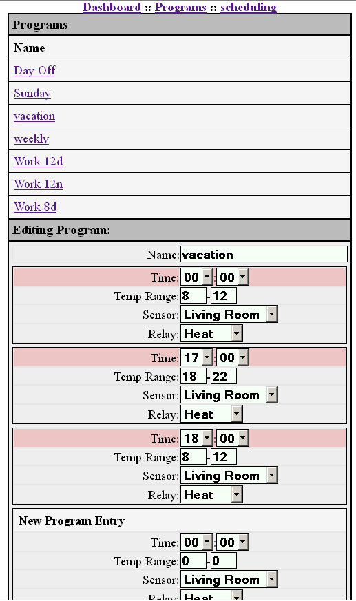
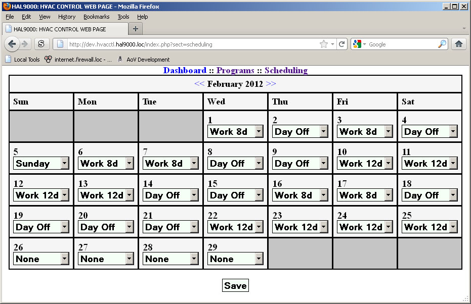
For the longest time I always wanted to make a thermostat that I can access via a web interface, and have very advanced scheduling features. Most off the shelf thermostats will allow you to make 4 to 6 programs per day, usually it's Mon-Fri and Sat-Sun. Well what if you work shifts, or get up on a different time on Sunday to go to church, or have a day off and want to override without actually changing the schedule? So I decided I wanted to code a custom coded app that could do that.

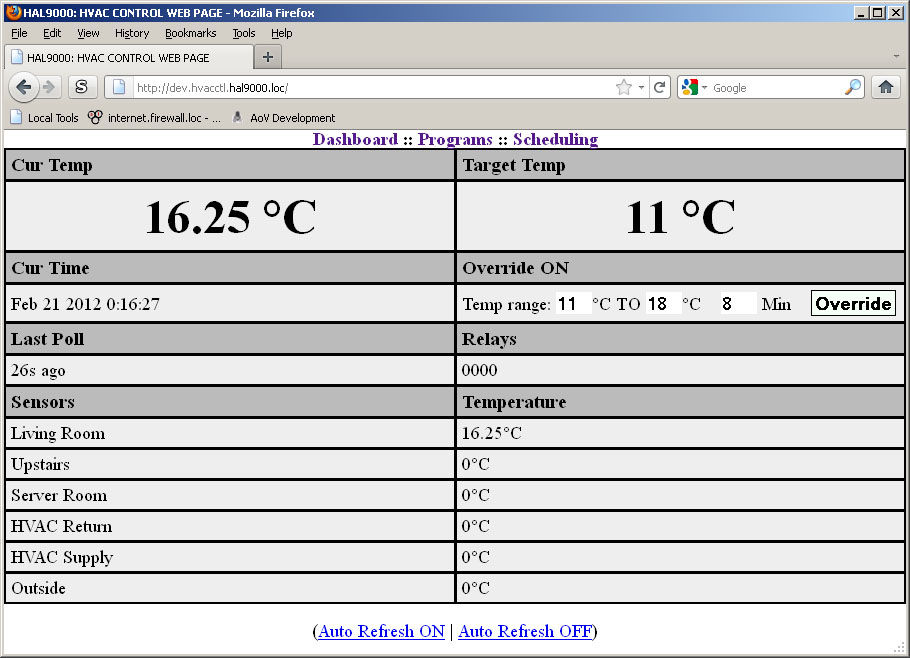
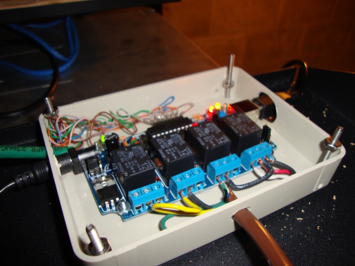
After thinking this over and doing research I finally decided to start making this a reality. First, I need a USB controlled relay board and USB controlled temp sensor. I found http://www.canakit.com which is actually here in Canada, and they have a 4 relay board with 6 temp sensors. How convenient, it's all in one piece of hardware. I need 1 relay for heat, 1 relay for the fan and 1 relay for the AC, which I don't yet have, but plan to get eventually. That leaves me with a spare relay I can do something else with in the future. It creates a virtual serial connection so it's very easy to code for, which is nice. I bought it not really knowing how easy it would be to interface with, so I got lucky.

lrg-1219-uk1104relay.JPG


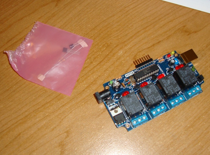
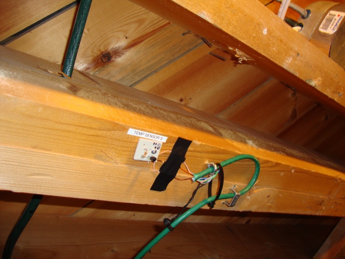
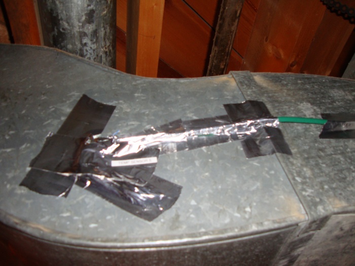
Also bought two temp sensors, they come with a resistor as they need to be connected a certain way with a resistor as part of the circuit.

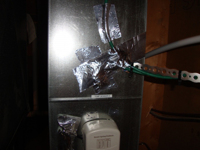
To make it easier to work with, I made a little circuit board using a random piece of plastic...

lrg-1220-dsc04156.JPG


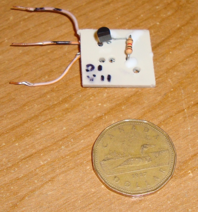
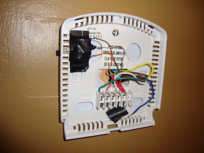
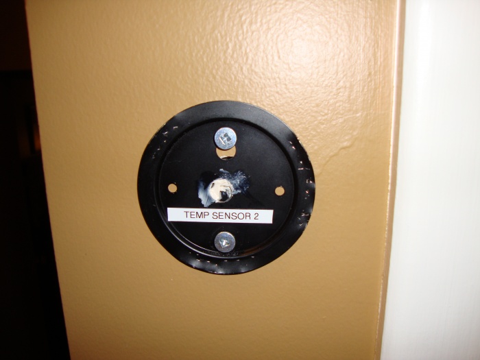
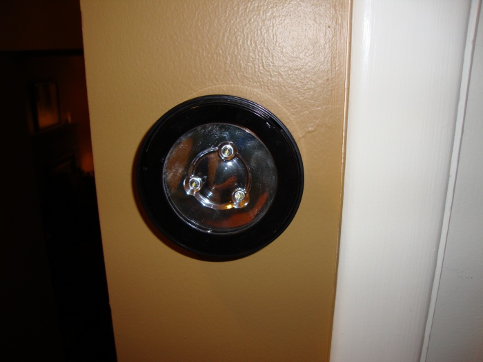
Crude, but should work. For now I'll be hiding one behind the existing thermostat if I can make some room, and the other I'm not sure yet, I just bought two in case I screw one up. I want one outside too but given it's winter I don't really want to be making holes in my outside walls, then going outside to work while I freeze my nuts off, so maybe adding the outside sensor could be a summer project in ~6 months from now.

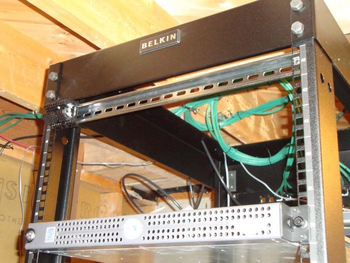
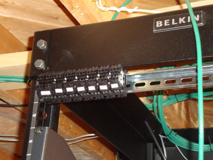
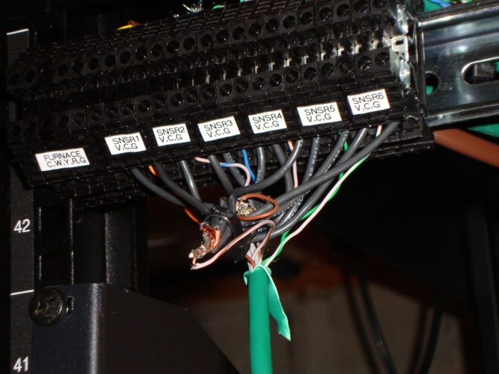
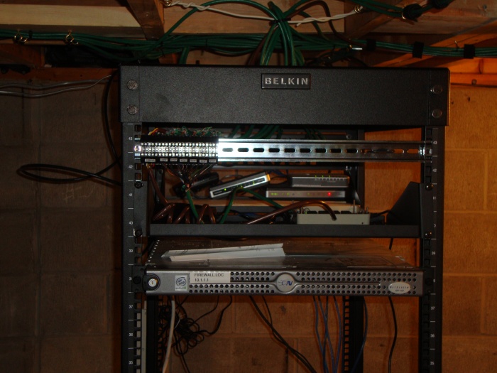
Now to interconnect all of this to the server, I wanted something that is clean and that can be disconnected easily, so upon my search for different types of terminal blocks, I decided that a DIN rail would be pretty cool to put on my server rack, so I settled with that.

lrg-1222-dinrail.JPG


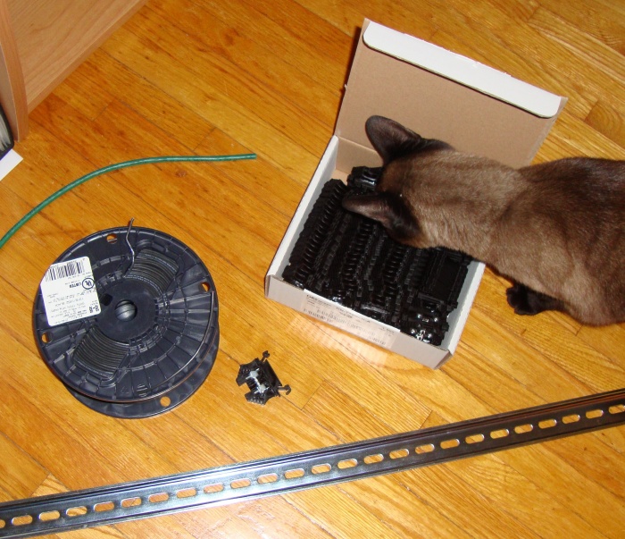
Just got that and terminal connectors the other day. Also bought some small wire for misc use as it was cheap. Got it at http://www.automationdirect.com.

I started a bit on coding a C++ class that can interface with the relay/temp board. Once I get that class working, I will then start on the actual control app and implement the class. I'm making this as modular as possible in case I use different hardware down the line, I can just code a class for that hardware then plug it in to the program, so to speak.

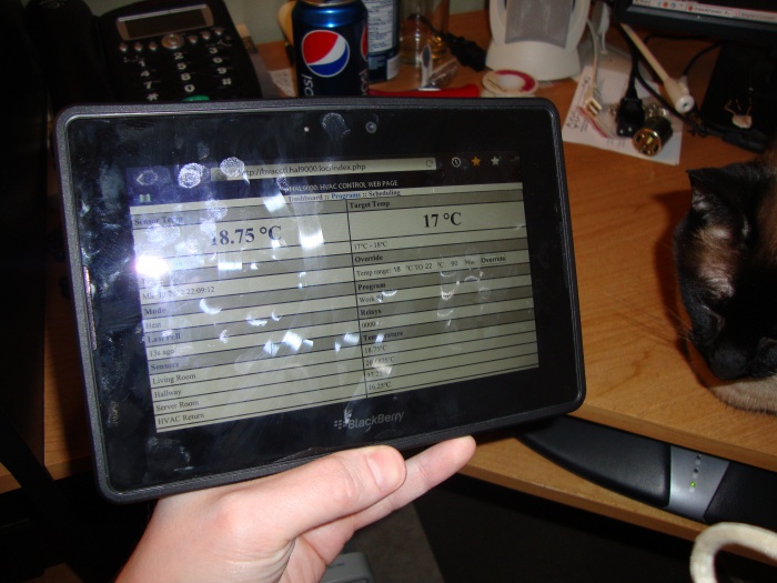
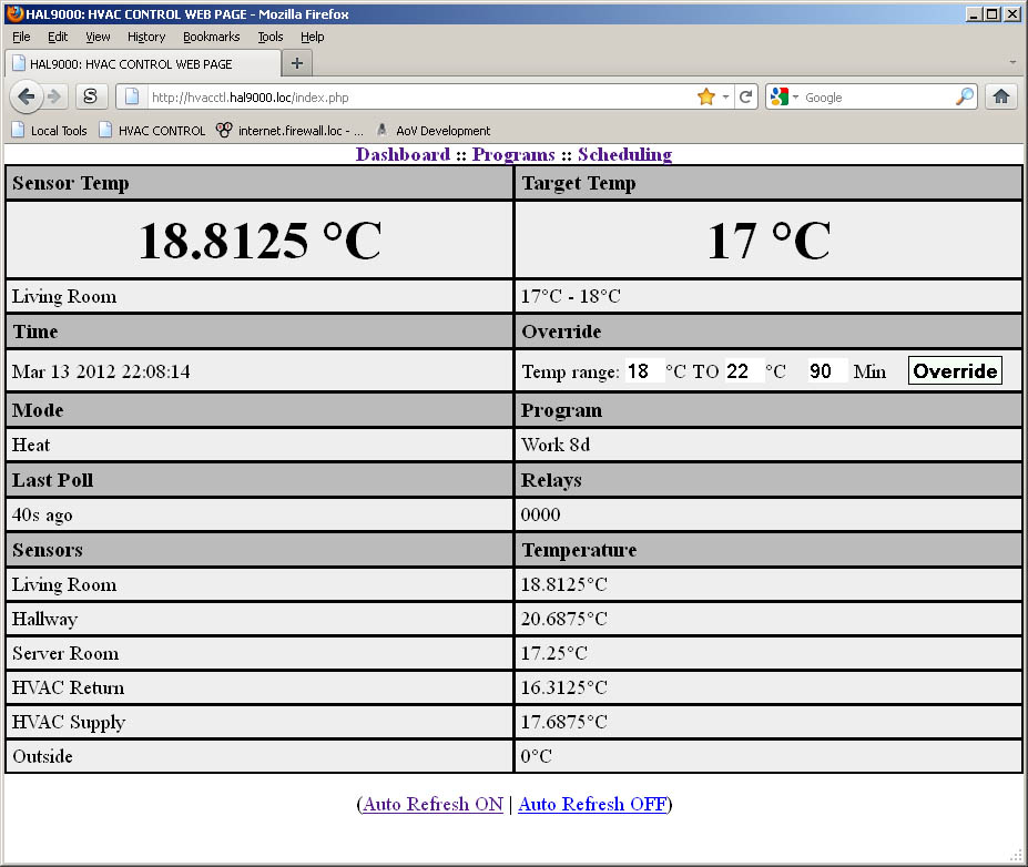
The program itself will store data in SQL and I'll be coding a web front end which I'll be easily able to access from any web enabled device. The scheduling and other settings will be in SQL, making it easy to code the front end.

I'm hoping to finish a rough app within the next few weeks. Given I work all day I only really get weekends to work on this. I sometimes work a bit on it during the week but not much.
 
Did not really do much on this today, but I did install the DIN rail.

lrg-1224-dinrailinstalled.JPG


I need to figure out the best way to go about labeling the terminal blocks. I think I will group them by function and just put a label across the group for the function, followed by what each terminal is for, so like for the furnace I'll put something like "Furnace: Y,G,W,R,C" and so on.

I'm mostly done the C++ class to control the relay board, and I've been testing it for the past few days.

So next step is to actually implement it. The control app will basically just be a looped app that checks the schedule every minute or so, polls the temp, and activates the correct relay based on existing temp and possibly other conditions. So in principle the rest of the app should be fairly straightforward. There will then be a php front end for actually editing the schedule and viewing current temp, what it's set at, etc... and option to override.

What will be awesome now is the ability to set the temperature with any wifi enabled device such as a smart phone or tablet, or from work when I VPN in.
 
I officially started shiftwork with my new job, which means I have more time now. I'm off tomorrow and after tomorrow, so I'm hoping to get more progress into this.

Tonight I coded part of the front end, I'll probably finish the rest tomorrow. Once that's done, I just need to code the back end which should be fairly easy as the hard part is already done (interfacing with the circuit board). In simple terms it's just a loop that will take readings, check the schedule, and act on it based on the readings.

Here's a preview of what the programming is like:

programview.png


Nothing fancy for now, basically each entry is a point where the "set temp" changes, until it hits another point either on that program, or the one from the following day. Eventually I will add more sensors so I can actually make it read the temp from a specific sensor at a specific time to determine what the temp is. Typically I'll be using the living room one which is central though.

Tomorrow I will do the scheduling part, where I can set a program to be weekly (happens on every Saturday, for example) or on a specific day. Most of the time I will be setting specific days and make it correspond with my work schedule.

The dashboard will be done last, it will basically just display the current temp and such. The back end will be feeding that data into the DB. There will also be a quick override function to override the temp for a specific time range. So if I'm at work, and decide to take my lunch later, or earlier, or not take it at all, I can adjust it accordingly from work.

This setup will be pretty energy conservative once it's fully tweaked. Will be interesting to see if I actually see a savings on my gas bill.
 
How about temperature averaging with multiple sensors?

Been searching forever for the discontinued DSC thermostats that tie into the alarm system. Reminds me I need to hook up the speak-n-spell....
 
I thought of doing averaging, but since my house is not zoned I figured I will just pick a sensor based on time of day. For example for my lunch I'll pick the one closer to the kitchen. For evening I'll pick the one up stairs etc. For now I'll only have one sensor, but I just ordered more, figured I may as well fill the board with the 6 it can handle.

I'm also thinking of putting a sensor in the return and supply duct, so I can keep the fan going until both temps match. That way any residual heat from the heat exchanger can be cleared. Same with AC once I get it, the coil will stay cool for a while after the compressor stops, so may as well keep the fan going a little longer.

I'm running into an issue with the controller though. If the USB cord gets disconnected, sometimes it does not recover properly and starts going haywire and just spitting out tons of junk data. This is a danger as if the relay is still on, it will keep the furnace running indefinitely until I get home. I've been trying to think of a solution to recover from that situation. I might power the controller by the server's power supply, and if that condition happens, it will just do a shutdown of the server and send me an email at work. Then I can go in the management console and boot it back up.
 
Very cool setup from a DIY standpoint. I manage about a dozen Prolophix NT160e T-stats at work. It has all of the scheduling options you were looking for.
 
Yeah I'm sure some of the commercial things can do all sorts of cool things. Though they're beyond my budget. :p

This is the scheduling page, forgot to post:

p2.jpg


I'll be off for 4 days starting Saturday so that should give me enough coding time to more or less finish the rest. I still have to code the override feature, and lot of the logic in the back end to handle the program of the day and what not. Been fighting mostly with that issue where it craps out if it gets disconnected, but I managed to get it to shut off the relay if it does that. Once I'm connected straight to the server I don't think it will be an issue, right now I'm using a USB extender through my patch panel so the board is on my desk and I can put my finger on the sensor to trigger it, and that USB extender has been known to randomly drop the connection.
 
More or less done the back end and front end now. There's still more testing and tweaking to do, but so far it's looking good.

I decided to omit the algorithm to determine when the furnace should actually start based on a scheduled time. Figured I should ensure that what I have works and then throw that feature in afterwards.

I'll finish up the tweaking tomorrow and then next time I'm off I'll start on the wiring. I ordered 4 more sensors so they should hopefully arrive by then.

I'll have one in the living room, upstairs, server room, furnace return duct, furnace supply duct and one outside. I'm debating on instead of putting one outside, I can just use data from the weather channel. Though real time actual temp would be kind of cool.

This is what the main interface looks like:

dashboard.jpg


The living room sensor is not actually installed so that reading is from the sensor just sitting in the server room crocodile clipped to the circuit board. It looks good on my Playbook too and is easily usable. I will probably do a "dry run" test for a couple weeks before I do the final hookup to the furnace. I'm paranoid about it randomly dropping the serial/usb connection with the relay turned on. Could be disastrous if it happens when I'm not home. Since I'm not using the USB extender now it has not dropped though, so think I'm good.
 
I'll be off work starting tomorrow so I will be doing the final hookup. Then it will be done!

I've been testing it all week and it's been working great (have the sensor and a light bulb in a bucket to simulate heating the house).
 
Started pulling wire today. Also decided to change up a bit the way I run wire around the house. Instead of just hanging in screw eyes and tie wraping any new cabling on the existing cabling that's passed through the screw eye (normally only one can fit) I decided that I will run a metal wire in the screw eye, pass the first wire into the screw eye, but use velcro straps to hold additional wires. The metal wire also acts as something to strap wire to between joists to prevent hang. So I did that today as well.

Wired the first sensor into the thermostat, so it's more or less hidden. I decided to make the sensor part itself stick out on the outside, for a more accurate temp reading. The thermostat will remain as a backup and be wired in parallel for the heat only.

lrg-1243-dsc04225.JPG


After I took that pic I realized I wired it wrong, The orange and brown/white wires are mixed up. Mostly mentioning this in case I come back and look at this in the future.... lol. I just made my own "standard" that I will follow for each sensor. Will make future troubleshooting easier. The sensors have 3 wires, so I just assigned each one to a color.


And here's some runs (some of those are existing Ethernet runs).

lrg-1241-dsc04226.JPG


Crawlspace data run, the one going to the far end is actually existing Ethernet, the one going behind the light is for the sensor.

lrg-1240-dsc04227.JPG


A run to the outside sensor. I will leave it coiled up at the end till summer. I don't really want to work outside in this weather, and I doubt any glue/cement I use would cure properly anyway. My plan is to have a small pipe go outside and have a down elbow with a cap and a couple holes in it. The sensor will reside at the tip of the pipe and the rest will be filled with insulation and caulked in. Will provide weather proofing for the sensor. I specifically chose a north wall which should provide an accurate reading. Most of these sensors are just for extra informational readings, more than anything. Though they will be used in some logic as I improve the control application.

lrg-1242-dsc04229.JPG


Din rail with the terminal blocks. They are all labeled to make it easy to identify each conductor.

lrg-1244-dsc04231.JPG


Hoping to more or less finish this up tomorrow, if not, next week. I'm off tomorrow but then start work again the next day. I still have one more wire run to do for the upstairs sensor. I bought a LED wallmount light which I'll be using to mask the sensor into, and the light itself may come in handy in the event of a power outage or what not.
 
Did the sensor connections:

lrg-1245-dsc04250.JPG


Though I'm not happy with how it turned out, it's just so messy. Part of the issue was finding a way to split a single wire into 6. Each channel needs a +5v and ground. I did more research and these terminal blocks can actually be jumpered. So I ordered some jumpers and I will have a set with grounds and a set with +5v and it will be much cleaner.
 
On the ones going to the sensors? Probably wont bother. But I will label the sensors so I know which block they go to. Basically I figure if they're labeled at both ends it should be good enough. Though I suppose if ever I accidentally cut a wire that's in a bunch it would come in handy to know what cable it is.
 
Ohh yeah they are labeled at both ends.

So I just did the final hookup. I just officially started the furnace using my Playbook. :D

I still have the upstairs sensor to hookup though, I will probably do that tomorrow.
 
And the upstairs sensor is done! Will post pics later, I'm tired, had a crazy couple days dealing with a roof leak. We've been getting rediculous hot/cold/hot/cold weather patterns latetly. Honestly not sure how I even got the will power to finish this, guess I knew I had so little left to do. Great feeling to mostly be done.

Just need to do a bit more labeling and polish the app more. I think I will go with some ajax, never coded that before but it does not look too hard.
 
Well this sucks, so I decided to reboot the server to ensure that the app starts off correctly and that everything is good. The board is doing it's stupid thing where it just starts spamming a bunch of crap instead of acting normal. Normally this happens if the USB gets unplugged, but now it's doing it no matter what. Tried resetting it and all, no go. Just can't get this damn thing to work properly anymore. Oddly, it seems to work if I login to it with picocom, but with my app it does not work, it just starts spitting out crap. Same thing if I echo data to it and "cat" the response. I don't know what picocom does differently as it seems to work ok with it, but anything else it craps out.

I wish this was true USB and not some serial emulation crap. So this is a big set back now. I'm back to the old thermostat till I can figure this out or find another board that works with the dallas sensors. The company is useless as far as support goes. You basically buy it "As is" and you're on your own. I have a feeling it's some defect on the board itself that causes this.
 
When I made my last post I was about ready to quit this. The control board was acting stupid, I was unable to get any support for it, and I was getting pissed off considering it worked before and suddenly would not work after a server reboot. I have been pulling my hair out all week.

Well, I think I may have figured out a fix. I still don't understand WHY it does this and I still think it's some kind of bug, but by looking at different online examples of serial connectivity and copying code around, I changed my connect function to this:

Code:
bool SerialConnector::Open()
{
	if(m_Path=="")
	{
		ScreenOutput("No path specified");
		return false;
	}


	//init stuff
	
	struct termios tio;
	//struct termios stdio;
	//int tty_fd;
	//fd_set rdset;


	//memset(&stdio,0,sizeof(stdio));
	//stdio.c_iflag=0;
	//stdio.c_oflag=0;
	//stdio.c_cflag=0;
	//stdio.c_lflag=0;
	//stdio.c_cc[VMIN]=1;
	//stdio.c_cc[VTIME]=0;
	//tcsetattr(STDOUT_FILENO,TCSANOW,&stdio);
	//tcsetattr(STDOUT_FILENO,TCSAFLUSH,&stdio);
	//fcntl(STDIN_FILENO, F_SETFL, O_NONBLOCK);       // make the reads non-blocking	


	memset(&tio,0,sizeof(tio));
	tio.c_iflag=0;
	tio.c_oflag=0;
	tio.c_cflag=CS8|CREAD|CLOCAL;           // 8n1, see termios.h for more information
	tio.c_lflag=0;
	tio.c_cc[VMIN]=1;
	tio.c_cc[VTIME]=5;


	//connect
	m_fd=open(m_Path.c_str(), O_RDWR | O_NONBLOCK);	


    cfsetospeed(&tio,B115200);            // 115200 baud
    cfsetispeed(&tio,B115200);            // 115200 baud	

	//this is required, it seems that it only needs to be called once per server reboot. It sets some kind of global thing that prevents the serial device (in my test: uk1104 from canakit) to go insane and spam junk
	tcsetattr(m_fd,TCSANOW,&tio);
	
	if (m_fd == -1 )
	{
		ScreenOutput("Unable to connect");
		m_conactive=false;
		return false;
	}

	m_conactive=true;
	
	return true;
}

I want to thank the author of this page:

https://en.wikibooks.org/wiki/Serial_Programming/Serial_Linux

The example is straight to the point line by line and easy to follow. Most of the examples I found were terrible to figure out.

I don't really know what every single line of code does, but the key lines are these:


Code:
	memset(&tio,0,sizeof(tio));
	tio.c_iflag=0;
	tio.c_oflag=0;
	tio.c_cflag=CS8|CREAD|CLOCAL;           // 8n1, see termios.h for more information
	tio.c_lflag=0;
	tio.c_cc[VMIN]=1;
	tio.c_cc[VTIME]=5;


    cfsetospeed(&tio,B115200);            // 115200 baud
    cfsetispeed(&tio,B115200);            // 115200 baud


In that order. I'm guesssing setting the baud rate may possibly play a role, but the code above also does. The connect function is the same as before.

It seems to me some of these parameters stick even after the program is done executing. I discovered that when I ran an example stand alone, and ran my program, my program worked. If I rebooted, my program stopped working. Oddly, running picocom did not actually set whatever global flags were being set, at least not permanently.

Either way, after several server reboots and several resets of the USB device it seems to work. Though, I may be calling it too early. I will let it run overnight before I take the app out of simulation mode, (basically this mode just ignores relay calls).

After tomorrow I will be off for 2 days, so I will run it live and see how it works out.

I really hope this works out on a long term basis, as I'm looking forward to actually putting this to good use and no longer need to keep messing with the thermostat programming day to day to accommodate my different shifts. This app is set and forget, which is awesome. It's why I did it. Given most people work standard shifts, consumer thermostats are designed for that, so I needed something to accommodate shift work.


Once this is proven, I will probably make up a full blown article explaining everything I did. Man, I'm so glad I got this working though, this spam thing was really starting to burn me.
 
Some more pics:

lrg-1271-dsc04269.JPG

Mounted control board and soldered in all the wires. Idealy I would have loved to make it terminal blocks instead but never even thought of ordering some direct mount ones when I did my order for the other stuff. I will try to find a piece of transparent plastic to use as the cover.

lrg-1275-dsc04270.JPG

Can now control furnace with my playbook or any wifi device


lrg-1269-dsc04271.JPG

I thought this was rather genius...


lrg-1273-dsc04272.JPG

Conveniently this is a great location for an emergency light, or just a light to look inside the closet beside it.


lrg-1268-dsc04273.JPG

Server room sensor (this "room" is basically my basement at this point)


lrg-1272-dsc04275.JPG

Return duct sensor


lrg-1267-dsc04276.JPG

Supply duct sensor


lrg-1270-dsc04278.JPG

Top view of rack where the control board sits on a shelf and the DIN rail is mounted on top. The actual server is closer to the middle and not shown, it's a little 1U SuperMicro server.


And lastly, here's a pic of the front end. I will probably tweak it more over time and make it look nicer.

hvacctl_frontend.jpg


We're int he middle of a heat wave right now so wont get to use this to it's full extent for another couple days, but in a way it's a good thing as I need to do a simulation test for a few days anyway before letting it activate the relays. Though I'm 99% sure I sorted out the issue now.

I also need to hookup the outside sensor but I'll wait till summer for that.
 
Nice. I was going for a Trane Z-Wave controlled thermostat, but your solution is so much geekier. I may look into that for a sprinkler controller. That's about all it needs, programmable relays. :D

Great work, man.
 
I just turned it into live mode now and turned off the other thermostat. Heading back to work from lunch break, wish me luck! lol

I'll be keeping a close eye on it from work. Though it was working fine when I tested it the other day till I decided to reboot the server and ran into that weird issue. That issue is now fixed.
 
Back
Top