help save my low end H110 motherboard!!!

dual-class

n00b
Joined
Dec 23, 2019
Messages
16
(IF YOU DONT CARE ABOUT THE INTO SKIP TO PARAGRAPH 3 NOW)

Ok so heres the deal, just made an account on the [H], have read a lot of threads on here and really consider y'all to be the last line of defense in terms of 'can this be done' or 'what happens id I...'

that said ive read a bunch of flaming replies as well so please cut me a break I am trying to hone my tech repair (read necromancy) skills, I have a working machine, this is not super urgent or 'please my games don't work and im about to pull my hair out' type thing... here goes


MSI, H110m gaming motherboard, acquired from a young fellow named larry who gave up on it due to it not overclocking, as well as him damaging it..

finally got around to it and unbent several LGA pins two nights ago, popped a spare Celeron CPU in there, moved on to the USB 3.0 header, Pin 1 (Vbus) had been snapped off (I should have just left it alone!!)

pryed the little plastic header surround off to get at the snapped pin and in the process I messed up three little bits on the motherboard!! one is a small gold colored rectangle (resistor maybe) the other two are black rectangles (polyswitch maybe?) (all three are the absolute smallest class of smds on the board maybe .5mmx1mm)

ended up repairing my dads old weller soldering gun in the process and pulled the snapped pin out and replaced it with an IDE pin from a much older dead motherboard, that at least went well

finally got the little gold rectangle to stick back in its spot and nudged if with my tiny flat blade to make sure it was holding


(PARAGRAPH 3)
ok so I plugged it in (known good PSU) and wagered a cpu and ram stick and then screwdriver bridged the jfp pins


getting error 'overcurrent detected on your usb device, system shutting down in 10, 9.... '


so I tried to mess with it some more and then some more, no dice

is there any way to simply break this circuit or some such!? at this point I have given up on the usb3.0 header working and just want to bypass this error if possible!!

this motherboard was dirt cheap so I have no qualms about snipping, melting, chiseling lol!!!

more than anything I just want to learn more about how to persevere in these situations, limited functionality is better than no functionality, and a motherboard in the hand is worth two in the bush.


I can post pics if need be, Help save my Baby!!! I have a radical modded case waiting to accept, stayed up all last night doing custom woodgrain finish work... OMG!!!!!!

thanks so much happy holidays All!
 
Lol. You just learner a valuable lesson: leave better alone. If the motherboard works fine with no USB header, leave the better alone.

But since the damage is done, we go to the 2nd question: can the USB be disabled. Possibly yes. If you check the BIOS menu carefully, there may be the option to disable USB devices/headers. Try searching through the BIOS menu.
 
Hi Janas, thanks for the fast reply! … cannot access bios at this time, stuck at the error code and then it powers down...


since it displays text on the screen I know it lives! CPU, IGPU, ram are working.


research says this code is usually a pin-short, but also the tiny damaged polyswitches which function as a thermal circuit breaker might make more sense.
I had considered just snapping these three trouble makers off to see if it will break the circuit and boot...

I am in uncharted territory here, deep behind enemy lines... waiting for the airstrike!
 
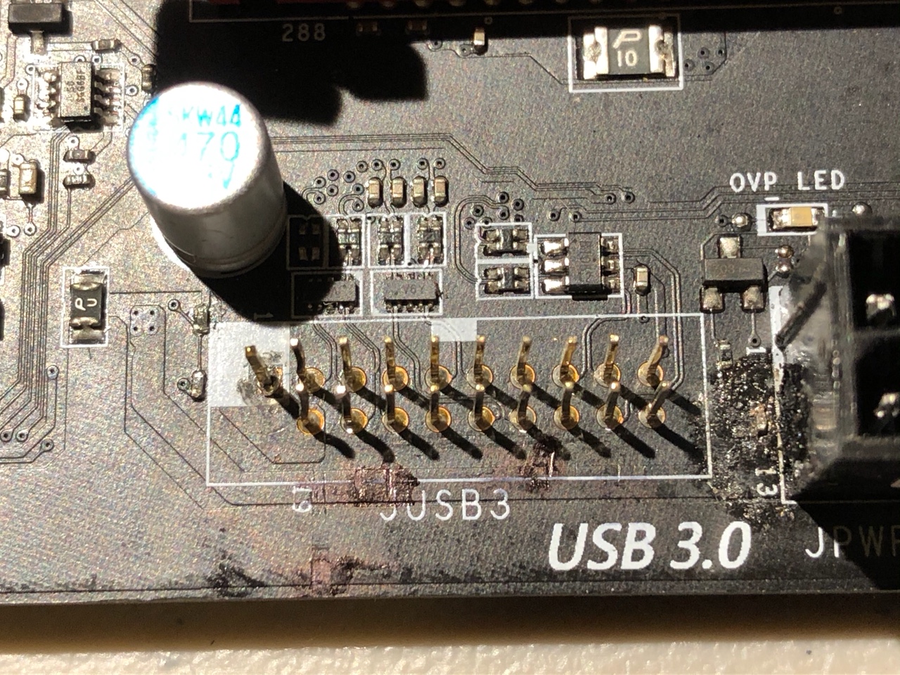
here is a pic!

two tiny black bits below the capacitor, one gold bit next to the 24pin connector (scorched earth lol)

h110 pic.jpeg


strangely enough the usb header does now work (15 second window) as in it charged my flashlight!


how to get around this pesky overcurrent error code, or nuke this subsystem to get booting again
 

Attachments

  • h110 pic.jpeg
    h110 pic.jpeg
    602 KB · Views: 0
here is a pic!

two tiny black bits below the capacitor, one gold bit next to the 24pin connector (scorched earth lol)

View attachment 210586

strangely enough the usb header does now work (15 second window) as in it charged my flashlight!

how to get around this pesky overcurrent error code, or nuke this subsystem to get booting again

Hahaha, that's a nice black char you got on that. Yup, I say it's been flamed and shish kebabed pretty good. You melted the PCB so it's going to be tricky to make spot repairs now.

That's a bit above my pay grade unfortunately, but I wish you luck :p
 
walked dogs, saw Christmas lights, read internet.

I tested the header pins with a multimeter vs another motherboard and im getting similar readings (several pins show continuity, probably through a capacitor... resistance creeping steadily upward)

may try to desolder the nearest capacitor (in the pic), that oughtta cut the water to a drip, and it seems like a reversible experiment!


and yeah I cooked it badly trying to use my crappy soldering pen to clumsily reattach the tiny gold smd…. LIKE 10 TIMES IN A ROW!!!
after fixing my dads old 140 watt weller gun with a fresh romex tip the thing was solid on the second try


Thanks for the replies so far, maybe a Christmas miracle will happen and someone can point me in the right direction.
 
Weller soldering gun is way too hot to work on a motherboard.
You need a soldering pencil/iron with a small tip.

Probably 40-50watts these days with lead-free solder. My bench
tech days were before that crap.

Clean up the charring as was said and remove the components you destroyed.
Use alcohol and an old toothbrush.

I see a lot of tinkering there...

The component to the lower left of the OVP_LED got very hot.

Look at the pin-out for the USB3 connector and find power pins.
Trace that pin(s) back and unsolder the driver/component to see if that cuts the overdraw.

It may be kind of difficult to fix now that so much damage has been done.

ETA: Those big screwdriver gashes are bad. That's a multi-layer board.
Those deep gashes can cut/short traces inside the layers.
May not be fixable with that damage.

.
 
Last edited:
Spartacus, thanks a lot for the reply!

I need better tools it would seem, namely some 10x glasses like ive seen some doctor/surgeons wear.

and my ebay pen iron was getting no traction on desoldering anything, the tip is maybe too blunt to get into the dip where pin meets board... I was spending like 15 seconds heating with no loosening occurring... I figured more heat faster is better than slowly cooking everything in the vicinity. this mobo was pretty much free so learning my lessons the hard way at least isn't expensive...

next time ill

USE A PLIERS! pull directly up on the plastic header surrounds, do not attempt to prybar it like opening a crate lol!!!
(the plastic surround is not even necessary in the end... so destroying it is no biggie)


I cleaned the char away and tried simply bridging where the little gold fellow was supposed to be with a solder blob... mobo was not happy I got lights for a fractional second then off..
soldered little gold brick back on a second time and now were back to the error message.


the power pin of usb 3 are the two end pins on the staggered end, the very last one standing alone in the white square is the one i replaced... ill try to trace it back and see where it leads.


If repair is successful, I can always get a USB 3.0 card with internal headers!!
I don't think im gonna be using up all my pci-e lanes here. no pci-e SSD and it may end up with a single gtx 1060!
 
still no dice... desoldered nearest capacitor... header ceased to deliver power to USB flashlight, computer still booted to 'overcurrent detected' error

replaced capacitor, header once again delivered power, error message still comes up


I am fairly stumped.. is the issue even local to the usb3.0 header....

I also plugged usb cables into all 6 rear ports simultaneously, no obvious signs of port damage, cables plugged and unplugged smoothly.


i feel like i need to do some multimeter testing while hooked up to power up and rely on the 5vsb rail and see where the voltage is and is not...


yep
 
Your soldering iron didn't work because it doesn't reach the melting point of the lead-free solder.
You still can't use the soldering gun. It's way too hot and you will continue to destroy things.

>>I am fairly stumped.. is the issue even local to the usb3.0 header....

Probably since that's where the shenanigans started. It's possible that more than one component
is shorted or blown, I'd bet on it.

Remove that component with the three legs that looks like it got hot.
And I would just remove the other parts in that charred area.

What type of component is in the shadow of that big cap on the left?

Does it look like the board got hot near those screwdriver gouges?

If you have a short inside the layers of the board, then it gets really tough
to fix. You'd have to find and cut power to the short and hope you don't
need that current path.

.
 
(IF YOU DONT WANT A FREE CHRISTMAS PRESENT SKIP TO PARAGRAPH 2 NOW!)
OMG..... too busy singing Christmas carols with the famalam, forgot to bid on a nice asus prime b250m-a for my custom made case, would have been case closed.... SOLD 17.50$ shipped--- shucks!


Here is a truly-epic-top-secret Christmas present for anyone who has been kind enough to read my humble thread


Ebay seller 'Hitexstore': location Elk Grove Village, Illinois: purveyor of oodles of 'bent pin specials' among other next to new tech goodies for peanuts
(I Have no affiliation with this seller, he just has all the right stuff- Cheap!! if you like to tinker or need spare parts... yep!)(10,000,000 butterfingered gamers cant all be wrong)

get a z390 today with a few bent pins for like 25$ shipped!! (just don't spread the word too far cuz I don't want too much Competition showin up on auction day!)
seriously unbending the lga pins is soooo darned easy compared to all this butchering ive been up to today!!
(im convinced Intel builds crafty puzzles into their tech to secretly encourage ingenuous modding while discouraging it at the front desk lol)

and now that ive read that I can do a custom bios-microcode insertion and put 9th gen cpus in this h110 motherboard... MUST FIX
(I am coasting on a holiday pig out here blood sugar is off the charts prolly!)


(PARAGRAPH 2)
Back to the nitty gritty, I noticed the 'new' solder didn't melt as fast or easily,

there are two small things side by side in the shadowed area that say '6y' on them, they seem to correspond some of the data pins

staggered left pins are +V... 4th from the left is ground on each row, the data pins seem to trace upward and into the component block above them
not sure where power is coming from but probably the bottom line with 'jusb3', I know the item to the left of the capacitor that says 'pu' is the 'polyswitch'
thermal circuit breaker... but it is not being tripped (flashlight still charges) maybe the overcurrent is just slightly out of spec, but not runaway

gonna test for 5v here and there, removing the capacitor seen in pic had no effect on error code, header power cuts out, need to paddle further upstream... LOL

little gold brick by 24p got the most love by far, think its a resistor, removing it has no effect cept header power cuts out, error remains

the majority of the cooking was done adjacent to the 24 pin connector and also on header pin#1 far left white square.


I don't think the gouges got heated that was just from my foolish screw driver prying... I put tape on the flatblade but in vain.
I colored them w/ permanent marker for corrosion protection!
I just wanna be able to fix stuff... the old man is always harping about the 'throw away society' the line must be drawn here!!!


I still need to wrap some presents,

I bid on lots of those hitex boards, sadly others usually bid them up to insanely high prices.
 
yeah its all about the intel boards with bent cpu socket pins... they usually go for cheap, and mostly work! that said prolly best to have a spare Celeron to test them with!


it sure would help if i knew what this little gold brick thing was, it is identical the the top row of 4 smds directly to the right of the capacitor in the picture, small golden brick with solder joints on each end, it is a smaller version of this type of device, but was in other respects visually identical until i cooked it. I am assuming it is a resistor maybe some sort of ceramic or metallic, it certainly has proven to be heatproof, and makes a solid thunk noise when landing on a sheet of paper.


i believe that could function as a current limiting device, and it being fubard could result in too much (I) flowing in the circuit

aside from shots in the dark i am really trying to logically deduce where the short (if it is a short) could be?
or could the golden brick cause the current anomaly by way of being damaged, or by way of a weak or nonexistent connection.

the error message persists with the little brick soldered on or snapped off... the motherboard did not start when i simple solder blobbed where the thing should be
but i am not certain that i was ever able to successfully reinstall it, despite it being attached and passing a cursory nudge test under a magnifying glass twice...

other than that there are these screwdriver gouges... they read 5v when grounded with the mobo off, psu on, so im guessing that is the 5vsb connection..
the header pins do not show 5v with mobo off psu on however... maybe 5vsb is shorted to ground at one of the gouges.


hmmmm....
 
update: still hacking away at it, getting these SMDs to stick is pretty hard!!

I need a tiny super hot soldering iron, did find a pair of 2.75power magnifying glasses and that helps out a lot.


sorry to ramble in my previous postings, blahblahblah blah.

lol have been reluctant to test for progress by removing more smd components, given the difficulty of re attaching them!


yep
 
Those tiny SMD parts are really hard to work with, some of them are damn near microscopic.

They are all originally placed and soldered by automation, not human hands.

The techs at the factory who do any required rework are very young, with young eyes and steady hands.
They also have exactly the required equipment to do the work. They have a lighted magnified
workstation with the correct temp controlled soldering iron.

If I was trying to get this board working for whatever reason, I'd remove most of the parts related
to that USB 3 port since you aren't going to be able to use it anyway. That whole cluster of small
chips connected to the data lines, all of it.

I don't think I'd spend a ton of time on it though. Those boards have to be very cheap on Ebay.

.
 
Update!!:

+1 to Spartacus, best answer selected... Sort of!

so I finally got over the 'i want my broken motherboard to be perfect' sentiment and decided it was time to push on forward.
an extremely difficult waterfall-in-a-deep-valley-by-sunset 1000 piece jigsaw puzzle helped to exhaust my patience over the last 4 days.

so I removed all the stuff above the pins, the capacitor, and the two little things directly below the capacitor.... cleaned it all up, can post a pic in a bit.


THE RESULT well now the thing for all intensive purposes seems Dead, shorting the pw-sw pins on the jfp header has no effect!!!

but then wait a minute and it comes to life for a sec, like a delayed reaction...
this repeats a lot, power cycling so to speak...

best part… no more usb overcurrent error... several times now the board has booted to the uefi bios and run for about 20 seconds at which points it shuts down again....

will do this about ever 10 power cycles
very peculiar,


so its back to the drawing board, it seems like it is doing some sort of protection mode... and cant decide if its ok to stay on or not...

But it wants to run... Im considering desoldering the little thingk that says P u next... i am fairly sure it is the thermal circuit breaker, maybe this would explain the intermittent/unpredictable results


I went ahead and reseated the ram and cpu, cleared the cmos, ... alcohol swabbed all the areas in question.... hmmmmm!

in summary... primary mission objective - accomplished!, overall stability - failure, more inspiration needed
will post a pic in a bit!!

help me out a bit more my e-pals!! possible ways to keep this bad boy up on a plane!!
 
whoops hit tab-enter

Update Part 2:
GLAD TO REPORT THAT THE MOTHERBOARD SEEMS TO HAVE BEEN REVIVED FROM THE BRINK, nay several rungs down into the ABYSS

after posting an hour ago, I continued with my game of motherboard Jenga! I removed the three pronged black piece next to the OVP LED, as well as the tiny component directly below it.

bad news now the motherboard was all dead, i had gone too far... no signs of life just a dim flash of blue from the clear cmos LED when i clicked the switch on my power strip...


decided not to give up the fight!!
commenced to solder blob the little blips where these two things (as well as the original offending snapped part below them) had been


I basically got a solder blob going on the tip of my pen iron and then used my tiny screw driver to scrape it off and smear it where it needed to be, finalizing with a little brush-brush touchup from the hot iron tip and screwdriver.

3rd try was the charm!!
on the three pin, first connected bottom left to top middle... no effect, still dead
undid that, connected all three pins with a big blob, also bridged the two missing pieces below independently... no effect
undid that, tried bottom left to top middle, bottom two components open circuit


What do you know it booted to bios and ran to the 2 minute mark no sweat!!!!

mr. Spartacus had suggested attacking the three pronged part initially, claiming that it had overheated... ive seen some bad memory chips on abused GPU and yeah they always have a darkened spot in the middle....

im wondering if i could have preserved the usb functionality by going that route first but Meh!!!
(its possible i could jury rig it to be a charging port but the cluster above the 20 pins was totally destroyed during removal!!)


I am gonna take a pic of the darned thing in a while and also of the build its going into!!!... anyone for a loose pci-e usb3.0 card, they can first class mail me LOL!!
(ummmm also I have no idea if this hackery knocked out the SATA ports located nearby, or if there will be some serious issues that bubble up.... I need to clean up this blob and make it durable so itll last…

FINAL LESSONS LEARNED...
motherboards are tougher than they look, don't give up on them on account of a few little burn marks or screwdriver gouges...
get some good high magnification reading glasses... in all things PC or tech, they will be your friend.

take your time, think first, but when you make stupid mistakes aim for a workaround, not a scrap it and start over

get a good headlamp... in all things life-on-planet-earth, it will be your friend!!


the historical Spartacus had it about right, live free or go down in flames!!! hopefully the former
im gonna get a little exercise then watch a college basketball game!!

Yep
 
OMG LOLMAO

so i couldn't leave the darned thing alone last night,

what can be undone, can be redone, and what can be redone, can be undone again...

so i was like you know what im getting in the swing of this soldering and sculpting little blobs and whatnot
im gonna slap that capacitor back in there and solder blob where the P-U polyswitch was and reactivate this header as a 'charge only' front panel set!!!


it was all smooth sailing strangely enough until i actually plugged my 20 pin to 2x 3.0 cable in there to test it... didn't even plug in my usb flashlight

the error came back!!!


lol
removed capacitor, desolder blobbed P-U thing.... no effect still error city!!!
CRAP!!!
removed header pin#1, broke the blob connection where the three pronged smd had been.... still no dice...
i was starting to lose it!!!
reblobbed the three prong thing except this time bridging the bottom left and bottom right pads.....

what do you know back to working bios!!!, oddly enough now the OVP LED remains lit! the board is red LED themed so i guess the more red leds the merrier :)

either way im done messin with it, screw havin 2 measley 900ma charge ports, dont need em!!
(i do feel like i have gained a bit of a better understanding of this subsystem tho which is good!! Last thing i want is to build this system up and then end up back in error code city!!)

I think the three pronged thing clears the error codes by switching... anyway that's my story and im stickin to it!! pci-e usb 3.0 card w/ internal headers here i come!!!


sorry to all that this has become somewhat of a blog more than a thread!!
in the end i hope what happened here can help some poor soul save their ailing computer someday!
 
Back
Top