Help identifying Port on Raspberry Pi2 and case

Joined
May 22, 2010
Messages
2,079
I have a black raspberry Pi2 case with a 2.2 inch screen. One manufactured by First From Asia and the other one I don't know because it doesn't say. The original one I bought from First From Asia has burnt traces on the board somehow and I'm not sure why, but it's shown here:
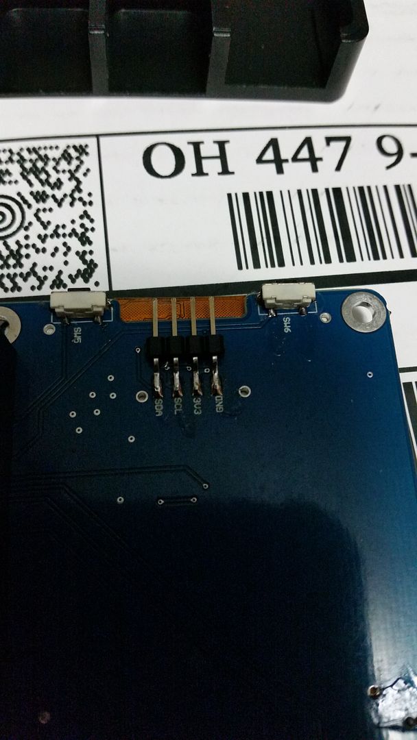


and here:


Also the first case sold from first from asia doesn't have this port in the case, but has it on the screen and I don't know what it's for:


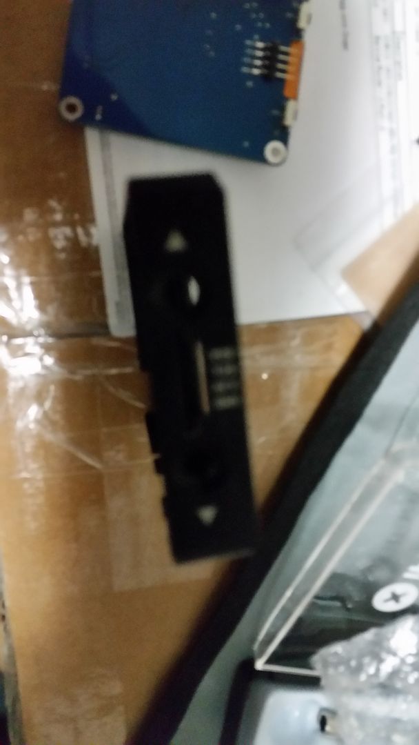
Could someone help identify this port because I don't know what it's for and have not attempted to use it, so I don't know why the original screen has burn marks on the trace where it shows signs of melting.
 
[QUOTEI "scharfshutze009, post: 1042165948, member: 215760"]Ok, but what is it for?[/QUOTE]
Video i presume. It looks labled you got 3.3 v ground then 2 data pins
 
Video i presume. It looks labled you got 3.3 v ground then 2 data pins

Where do I get the connector for this then?[/QUOTE]
well checked into it a bit and that display connects to the gpio pins on the pi. So the connectors are just jumper wires. And you will need to connect to the correct pins on the pi...
 
Last edited:
Where do I get the connector for this then?
well checked into it a bit and that display connects to the gpio pins on the pi. So the connectors are just jumper wires. And you will need to connect to the correct pins on the pi...[/QUOTE]

So, you're saying that the I2c connector on the back of the screen already connected to the C64 connector connects to to where it says display beside the connector on the Pi2 board, but why does the case have an external slot to allow connection to this port and was does the connector or cable look like because I'm finding a lot of matches. Therefore, I'm not sure which i2c cable or connector to get. Is not having this the reason the screen doesn't work or why the traces melted on the first screen though and if so please help me find the right part to prevent this in the future.
 
Last edited:
Video i presume. It looks labled you got 3.3 v ground then 2 data pins

Where do I get the connector for this then?[/QUOTE]

Yes, that's right I have 3.3v to the left of GND and to the immediate right of SCL to the right of SDA, which you can't tell from the picture because the picture is blurry. SDA and SCL must be the data pins you're referring to.
 
SDA is data
Scl is a clock
3v3 is 3.3v
Gnd is ground

The only things I found was a discussion on what diver worked that display and that they needed to load a obscure generic driver to get the display to work. And that those pins connect to arduino and raspberry pi gpio pins dont ask me which ones that should be well documented... As for the connector make your own seems to be the theme of the pi and arduino...

Thanks now if only I could find the driver for the display. As for the I2C connector I guess I have to make my own as is the theme of pi and arduino as stated, but can you help guide me on how to start. Obviously I need 4-pins and 4 wires for the I2C connector, but where do I get the parts to make it with and what do I make it with?
 
Thanks now if only I could find the driver for the display. As for the I2C connector I guess I have to make my own as is the theme of pi and arduino as stated, but can you help guide me on how to start. Obviously I need 4-pins and 4 wires for the I2C connector, but where do I get the parts to make it with and what do I make it with?

I found a premade connector that will work, but I still need to download the driver for the screen.
 
Back
Top