SINGLE SLEEVED WIRE GUIDE BY KAMASTER
MDPC-X SINGLE SLEEVED CABLED AT THEIR FINEST")
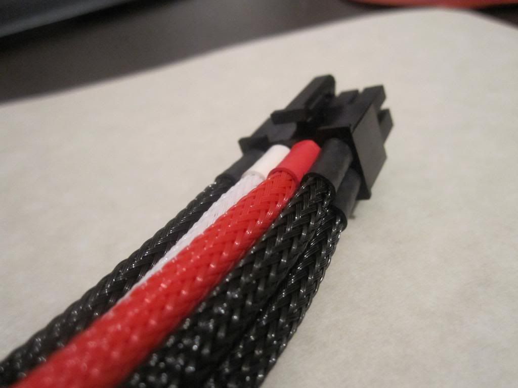
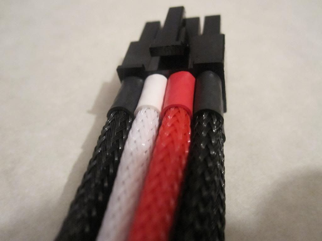
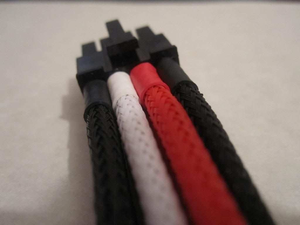
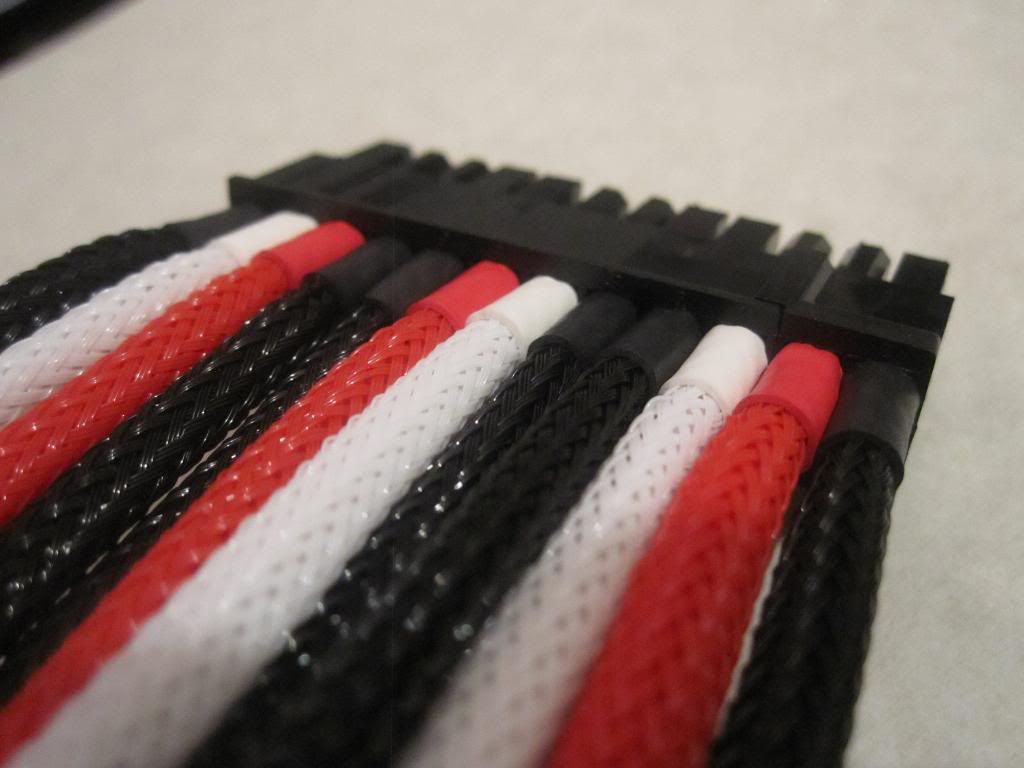
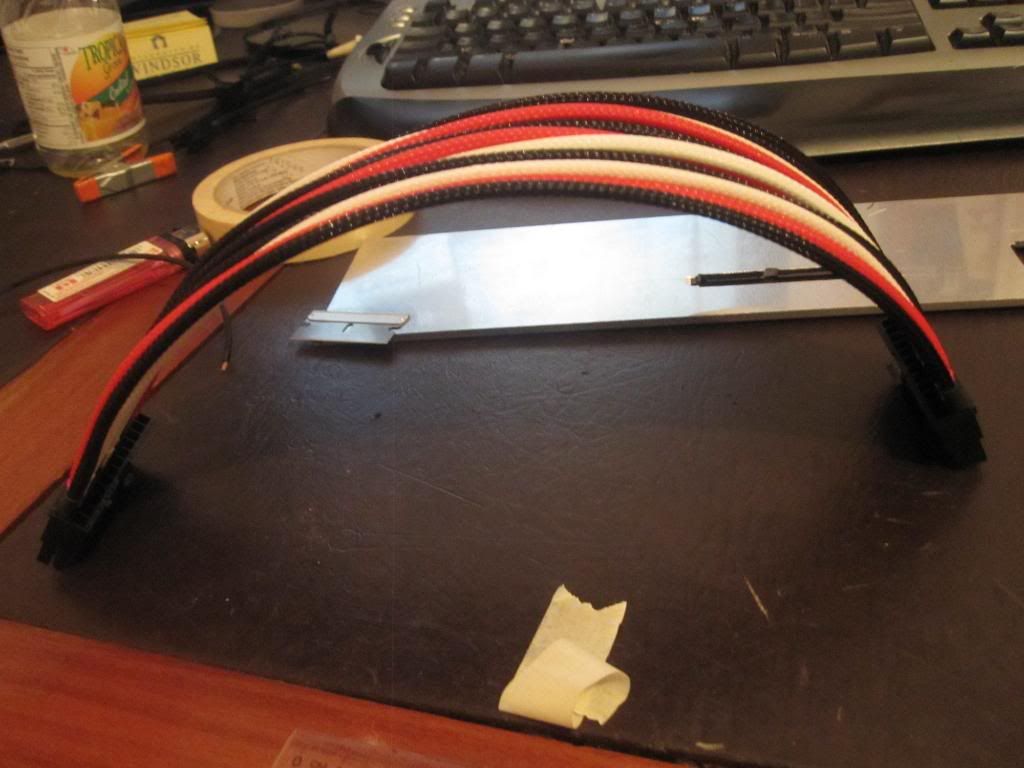
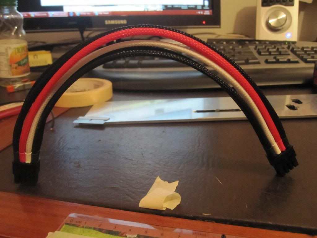
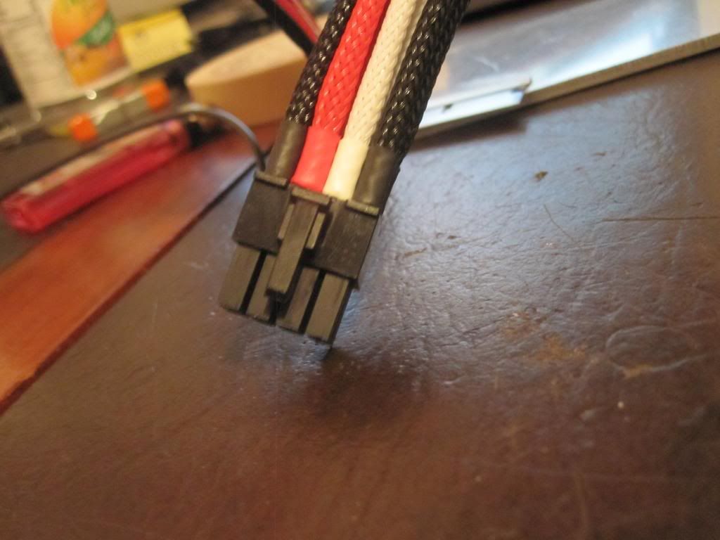
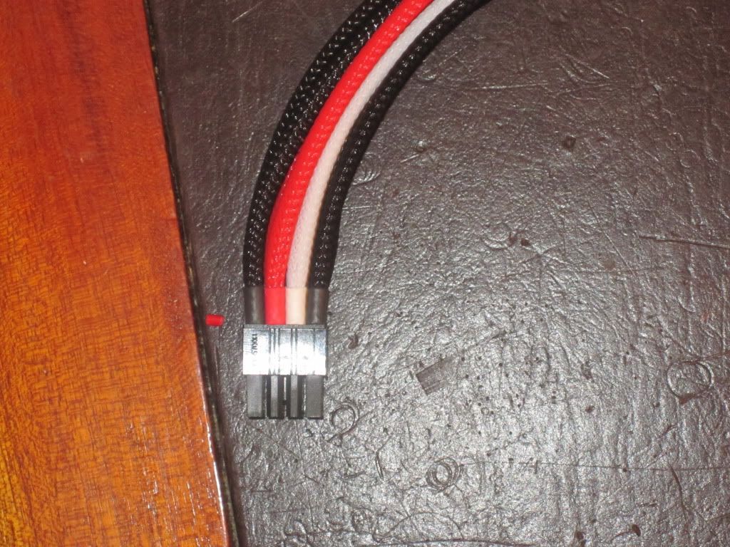
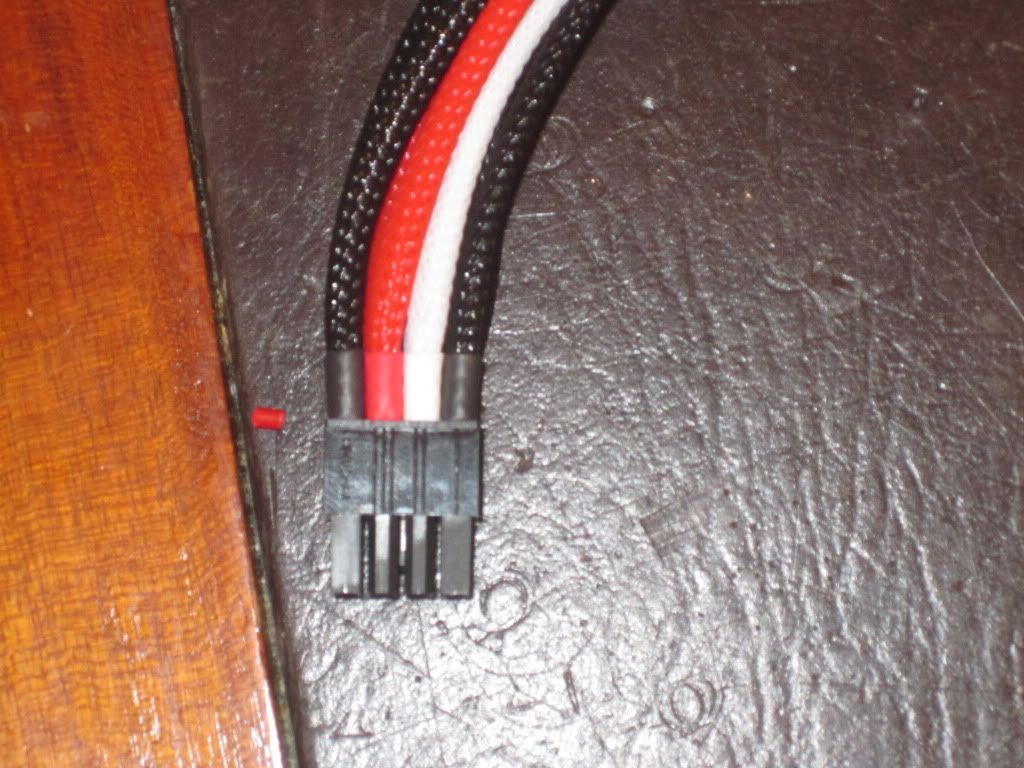
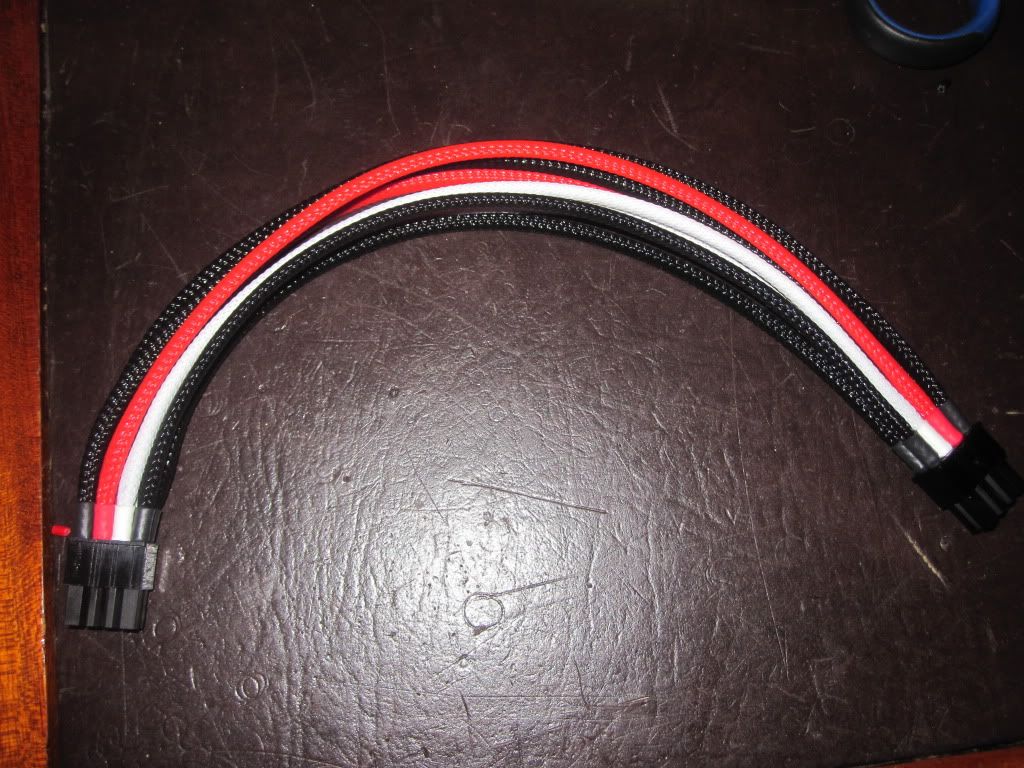
I received a request from a member of another forum for a guide on how to single (individually) sleeve your power supply or custom made cables with MDPC-X sleeving and heatshrink. This is my technique and it can be done many other ways I find this works well and gives good results (all the heatshrink lines up perfectly).
I have used these techniques on my FERMI 2 build, CHECK IT OUT!!!!!
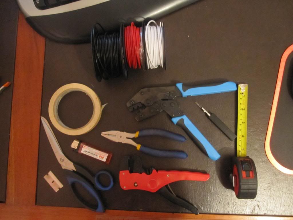
First you are going to need some tools and tools, heres the list:
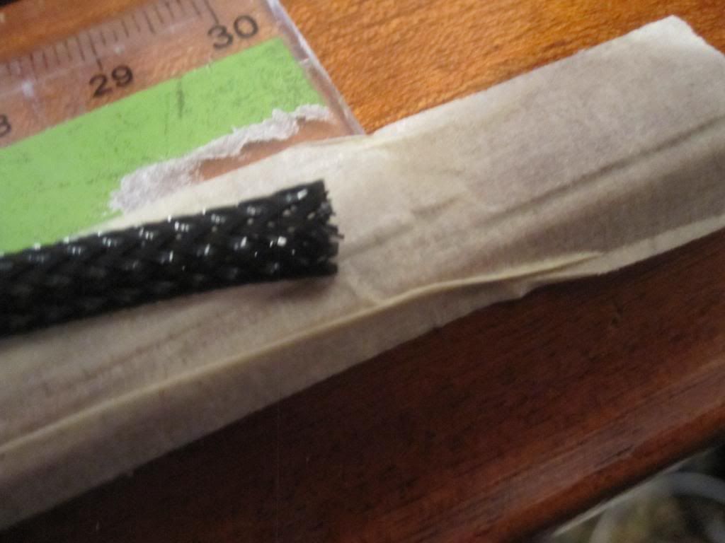
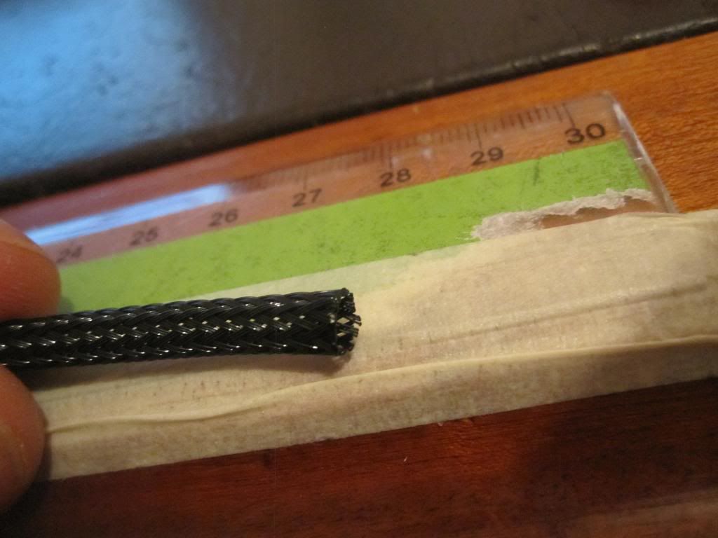
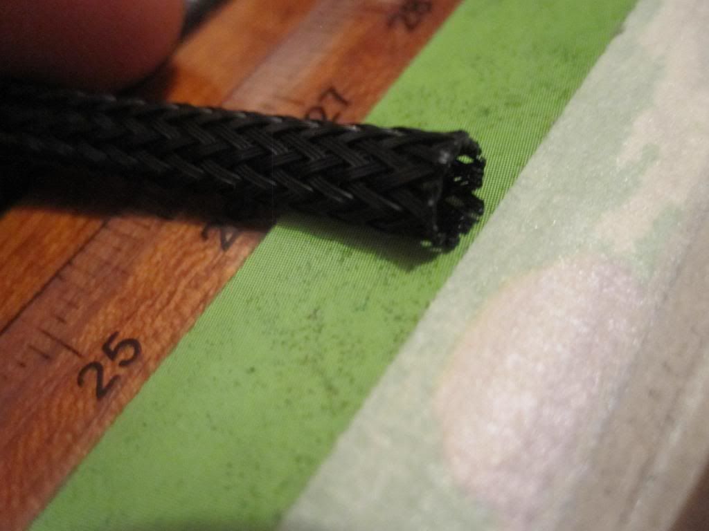
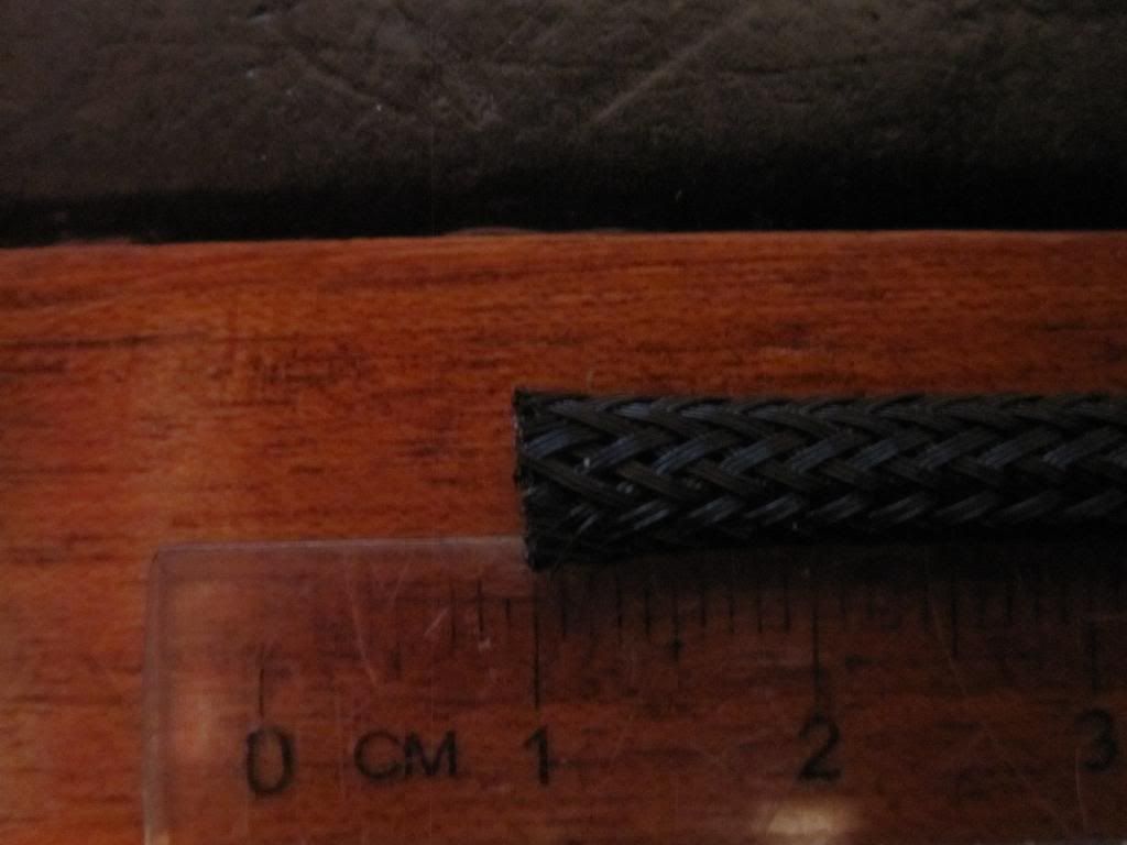
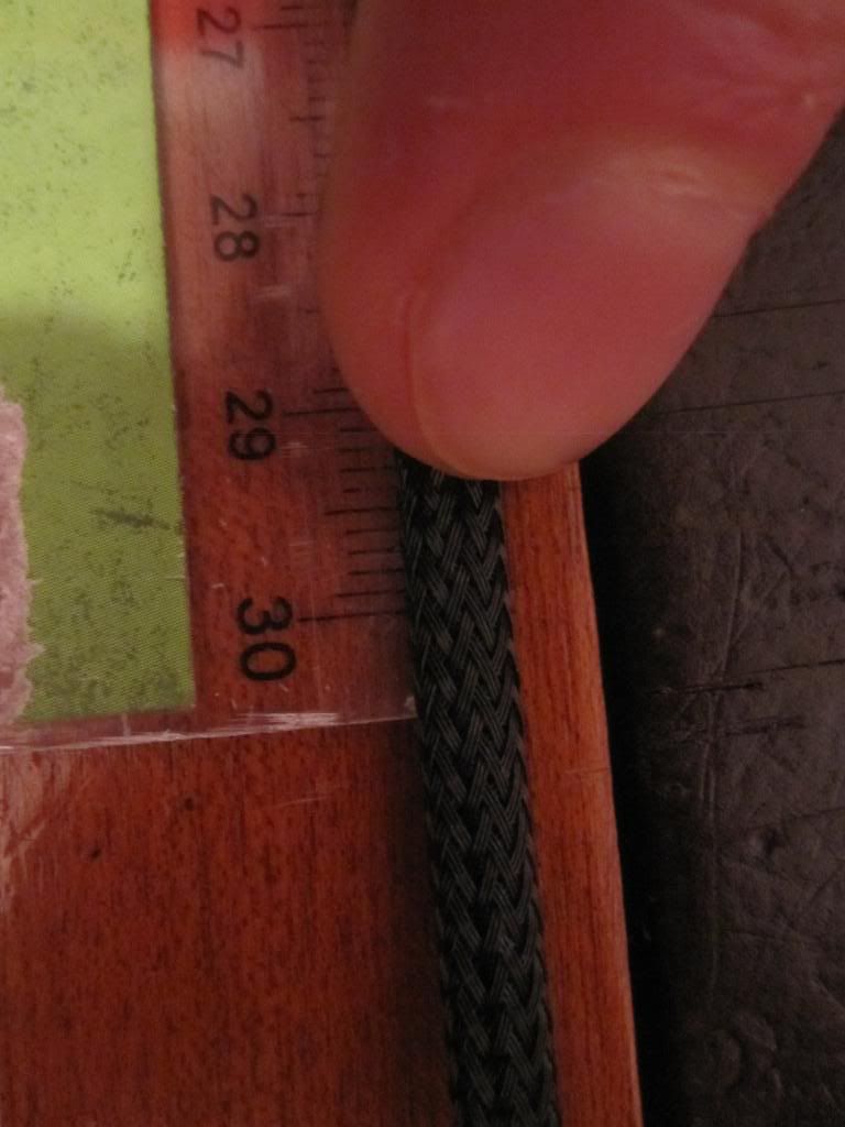
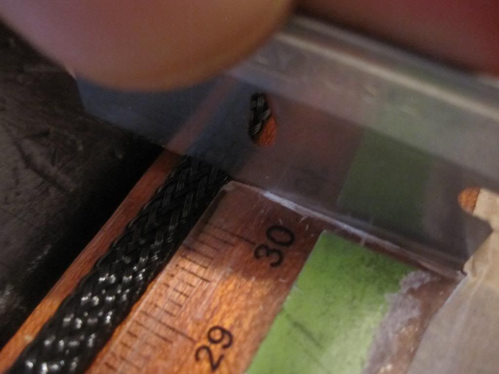
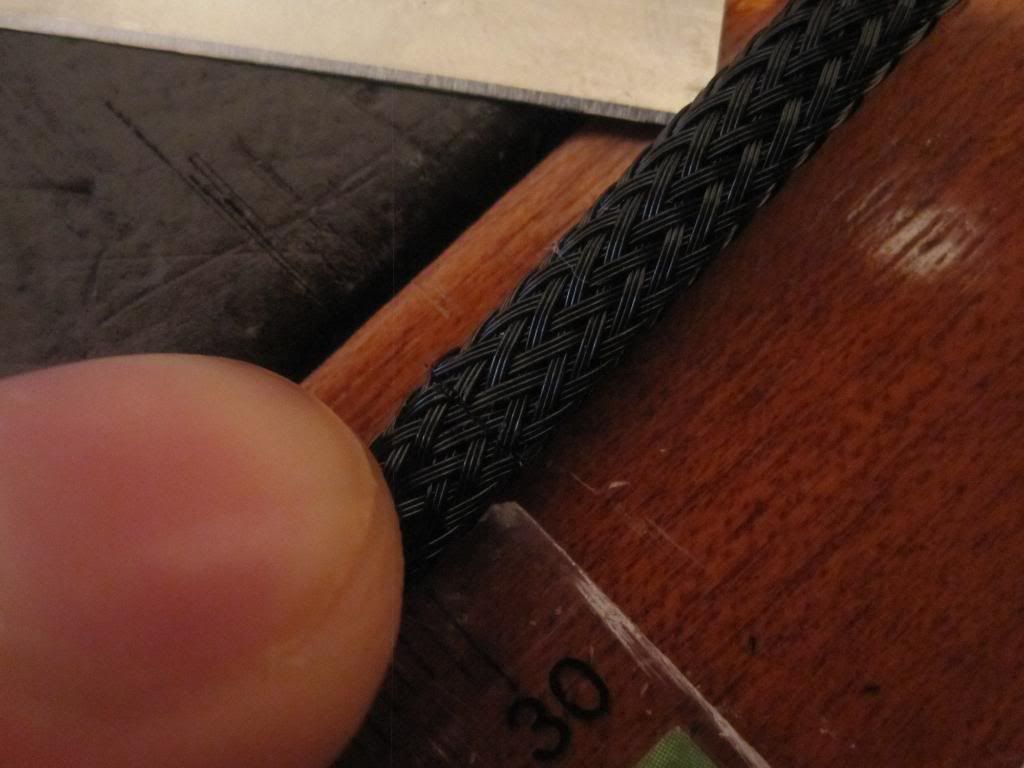
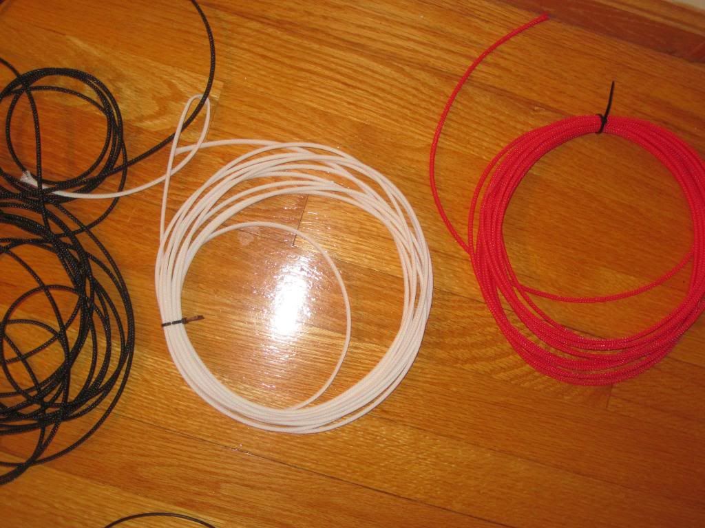
1. MDPC-X small sleeving
2. MDPC-X Pre-cut heatshrink (15mm long)
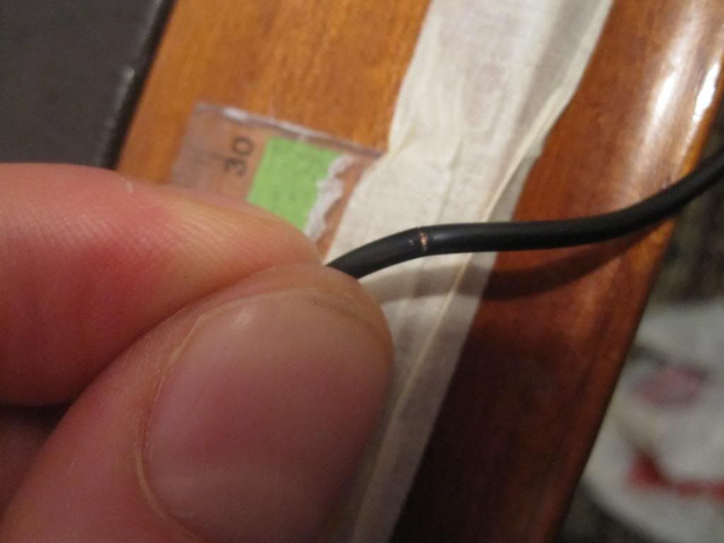
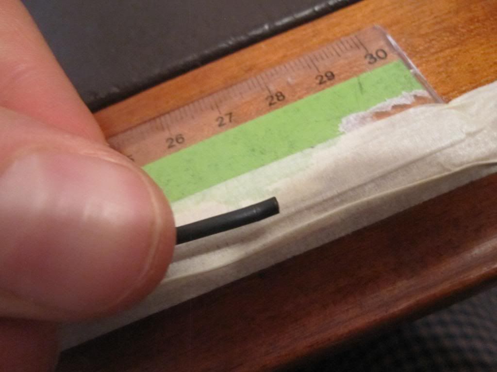
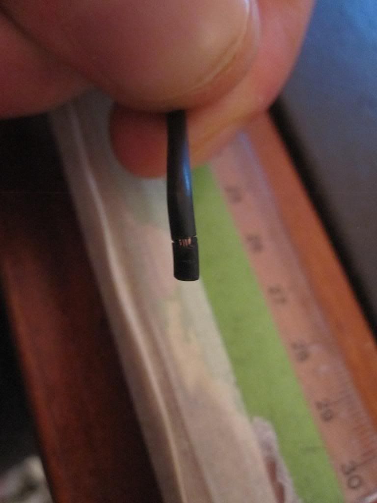
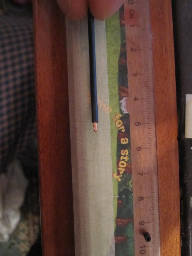
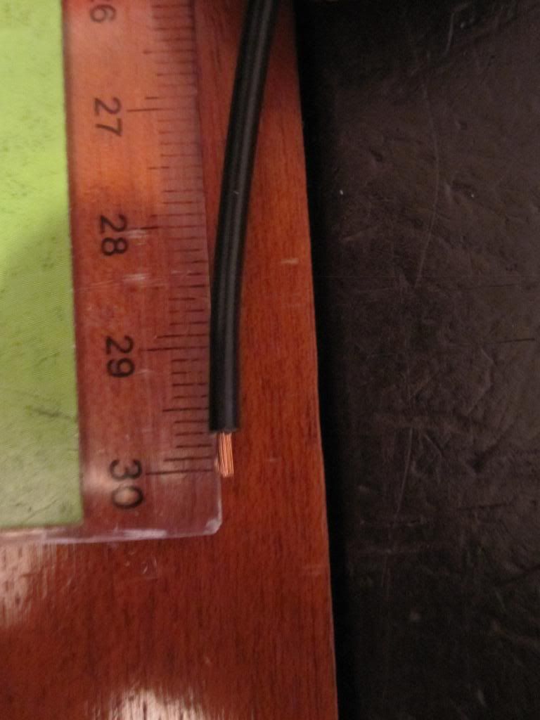
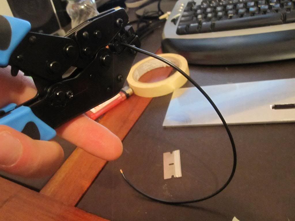
3. 18 Gauge Wire ( I used automotive stuff - seems to have a thicker pvc wall than the regular stuff)
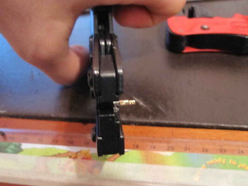
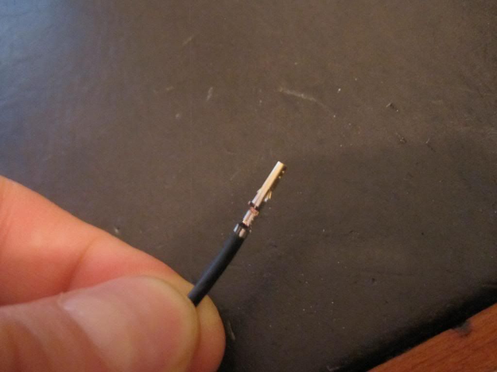
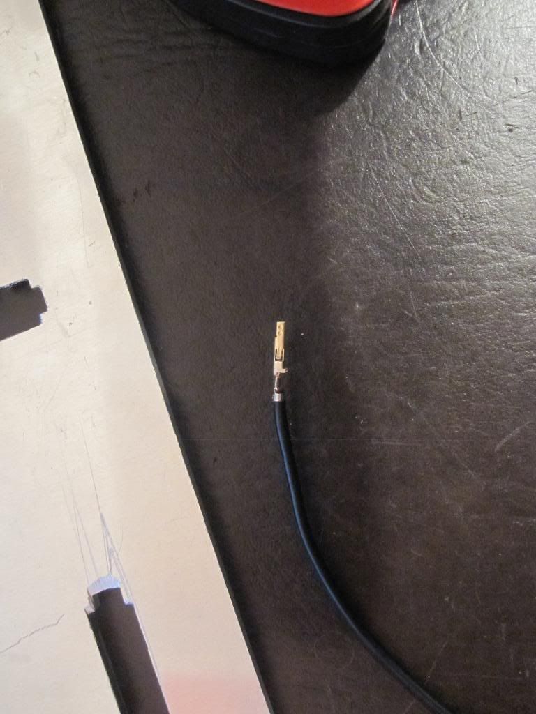
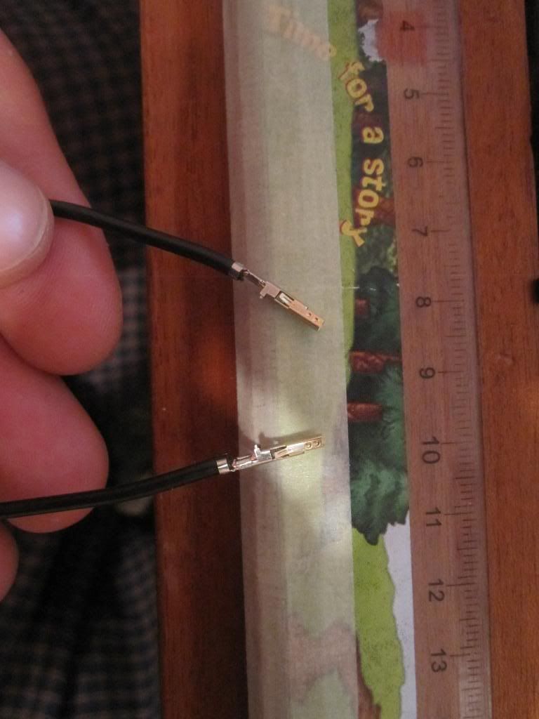
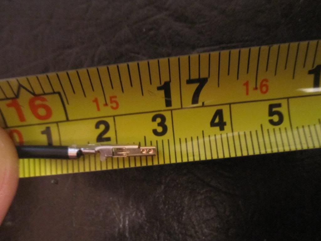
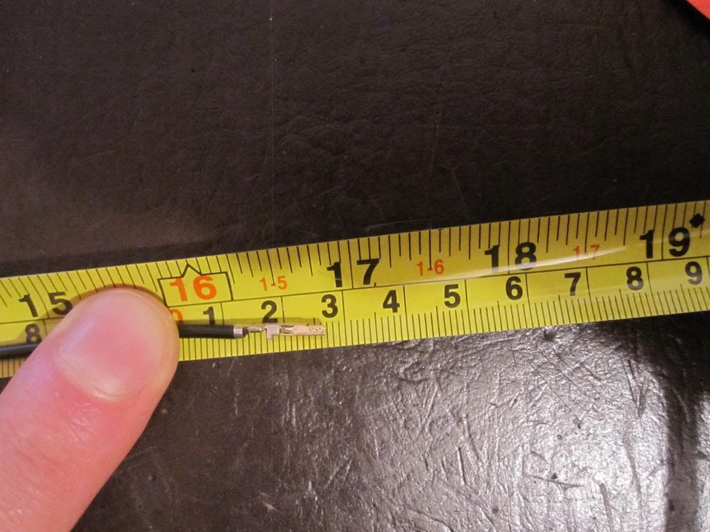
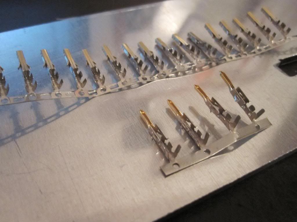
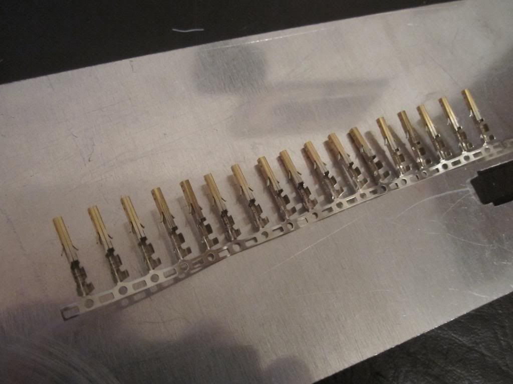
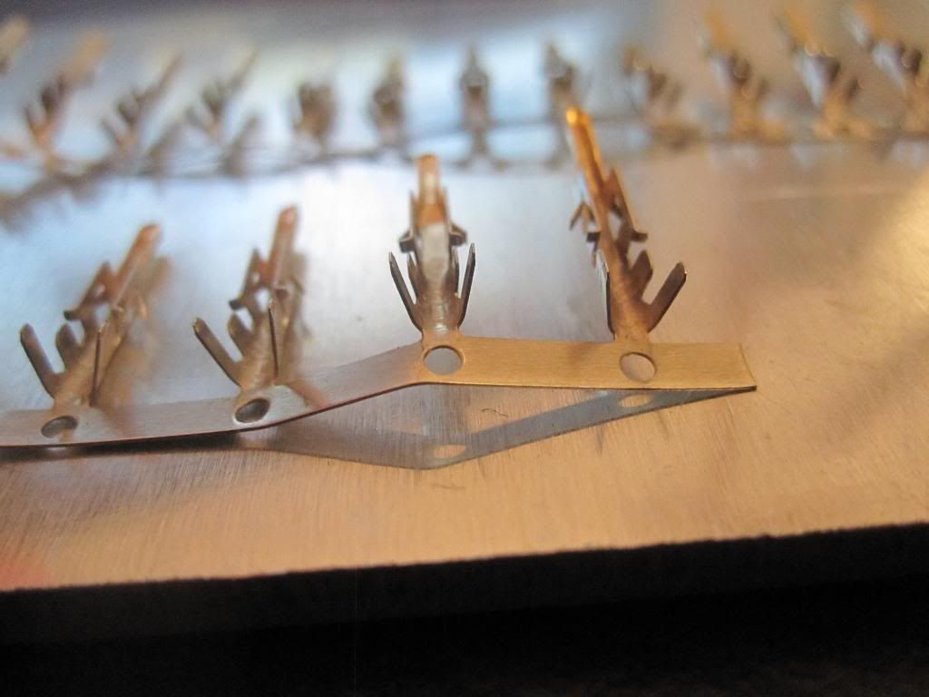
4. ATX male and/or female connector pins
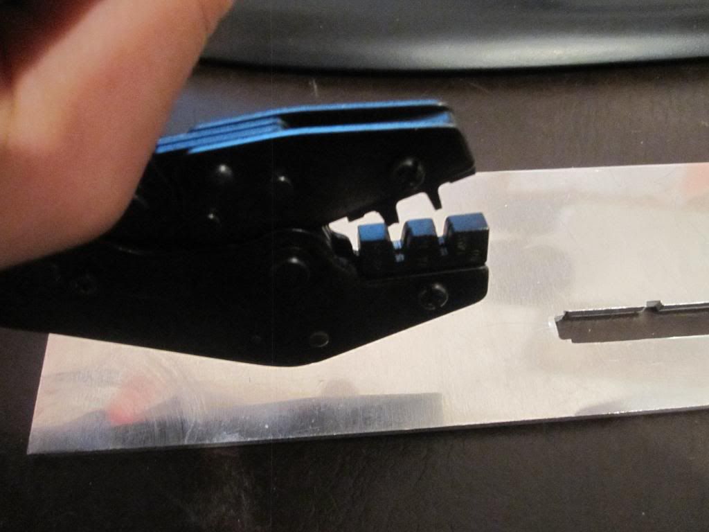
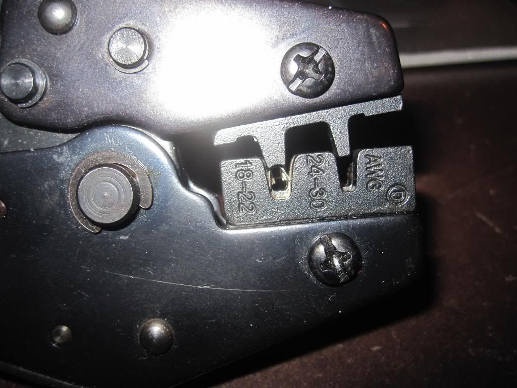
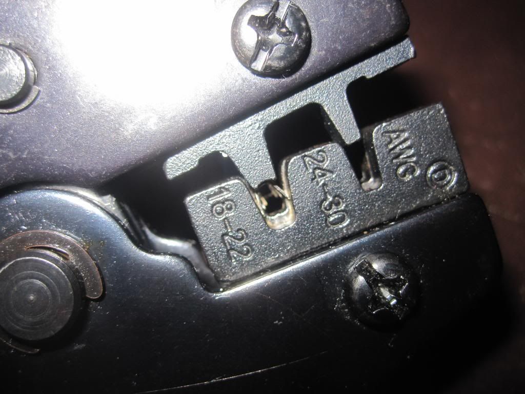
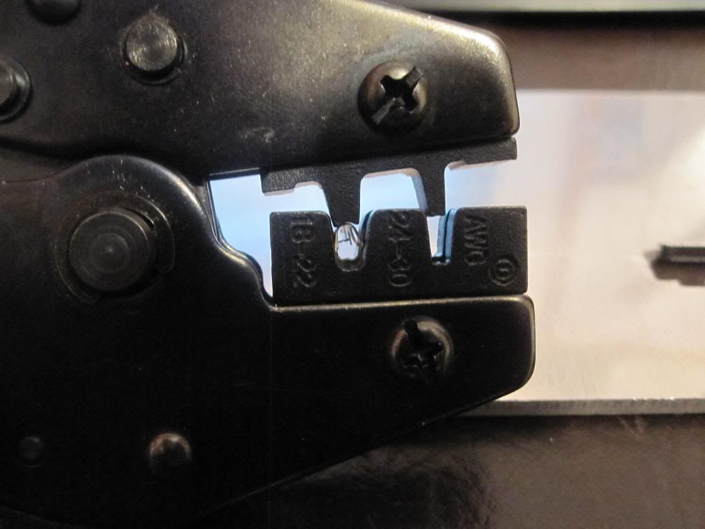
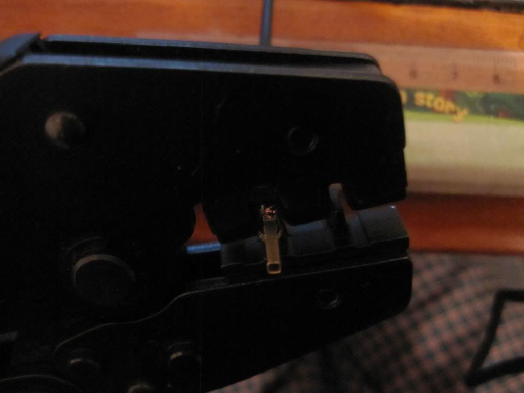
5. ATX pin Crimping tool
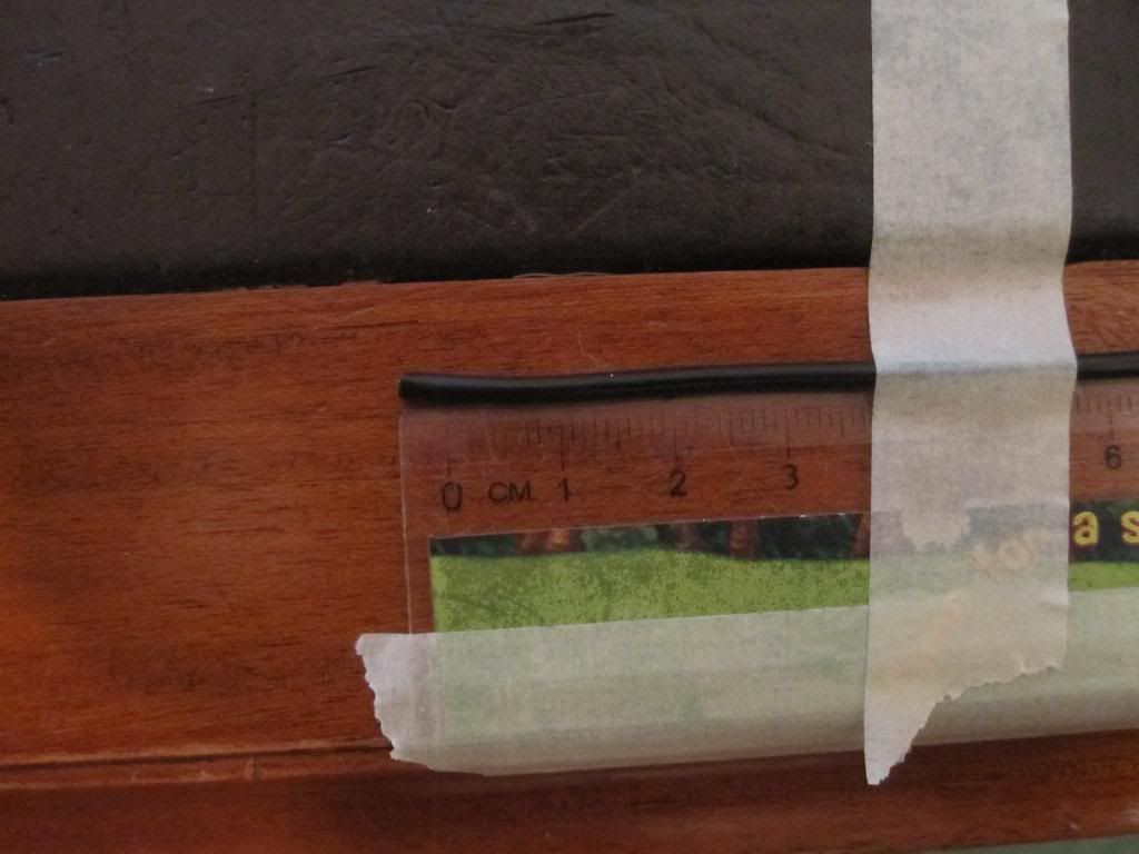
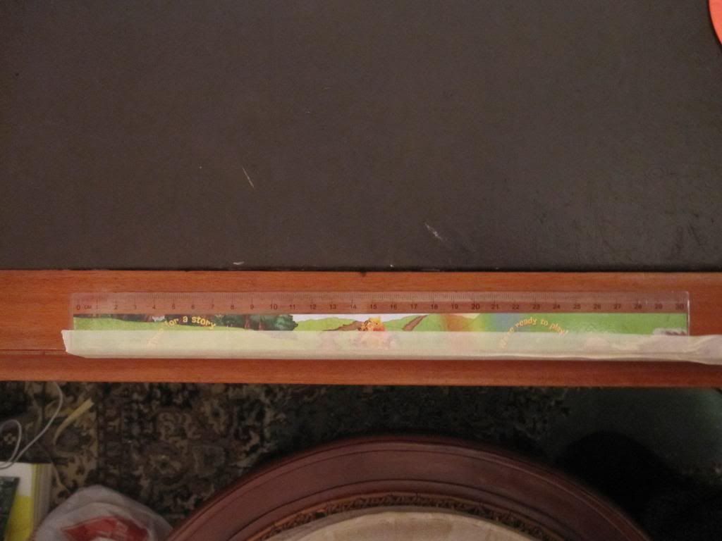
6. Ruler
7. Masking tape
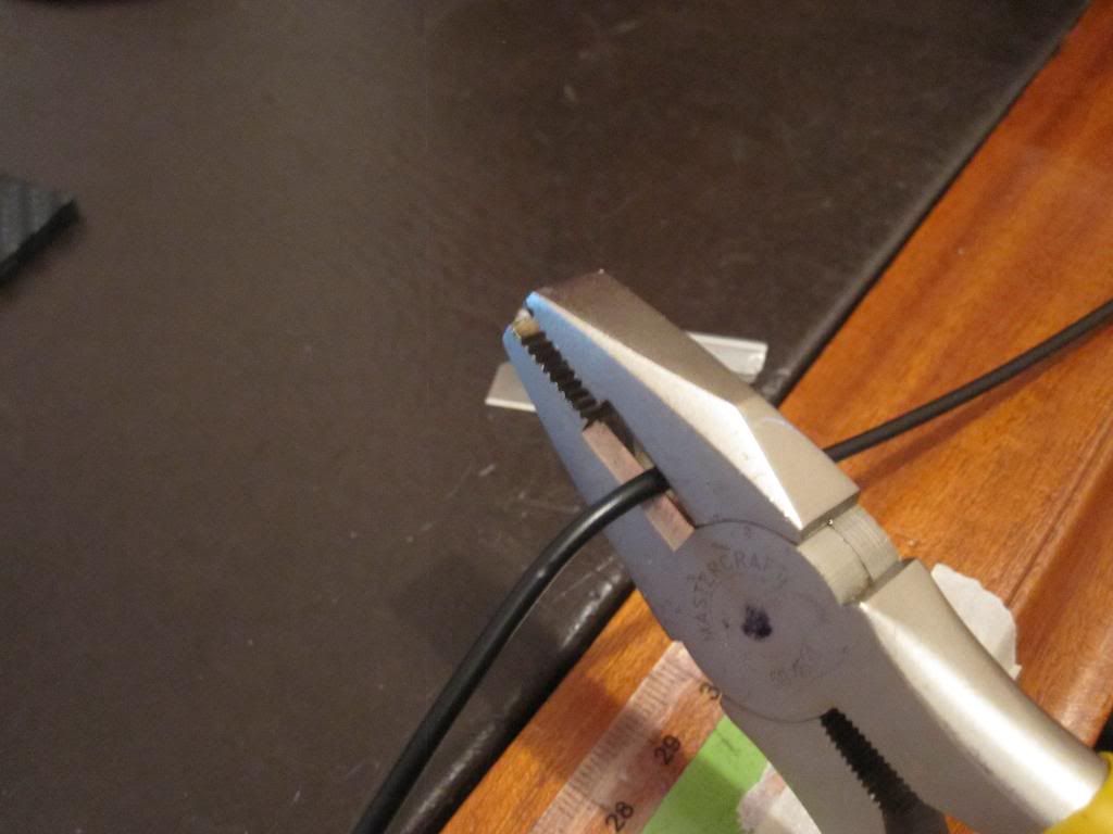
8. Pliers (that can cut wire)
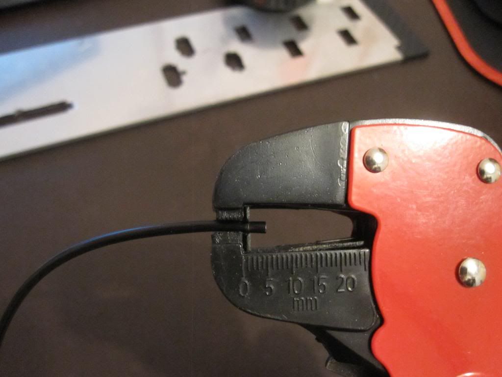
9. Wire stripper (preferably like the one i have but standard ones are fine)
10. Measuring tape
11. Good pair of scissors (dont use a cheap pair if you want good results $15-40)
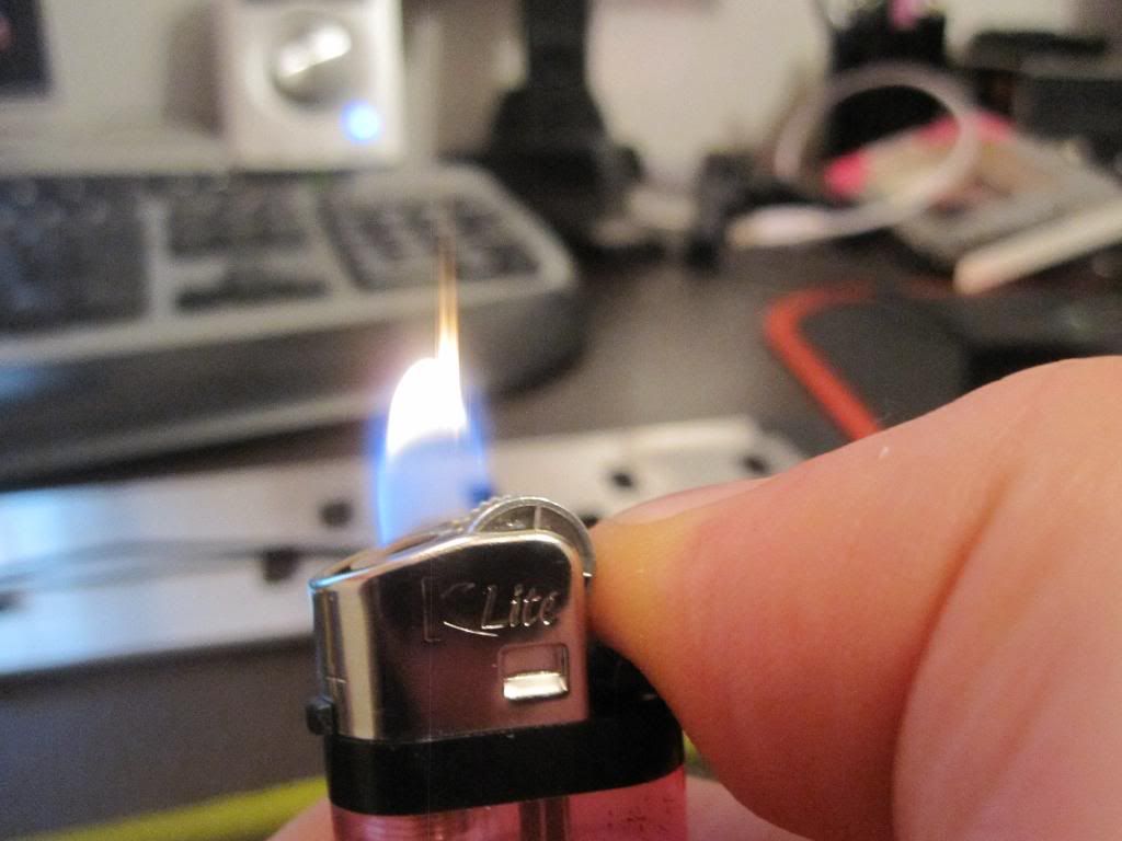
12. Lighter
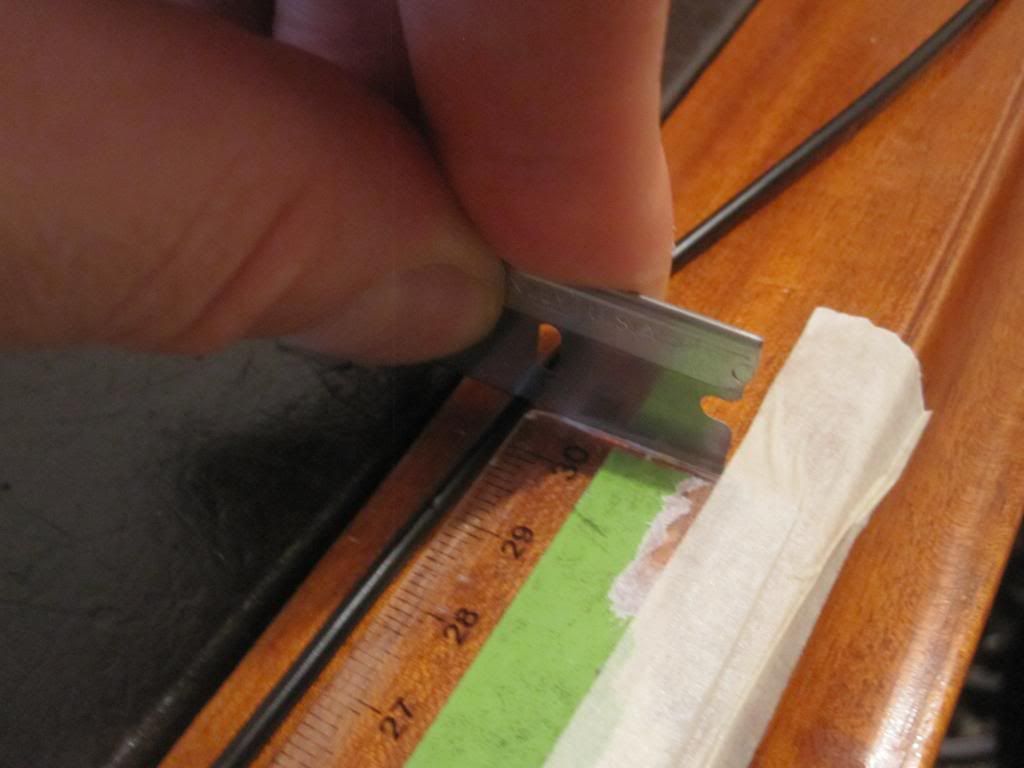
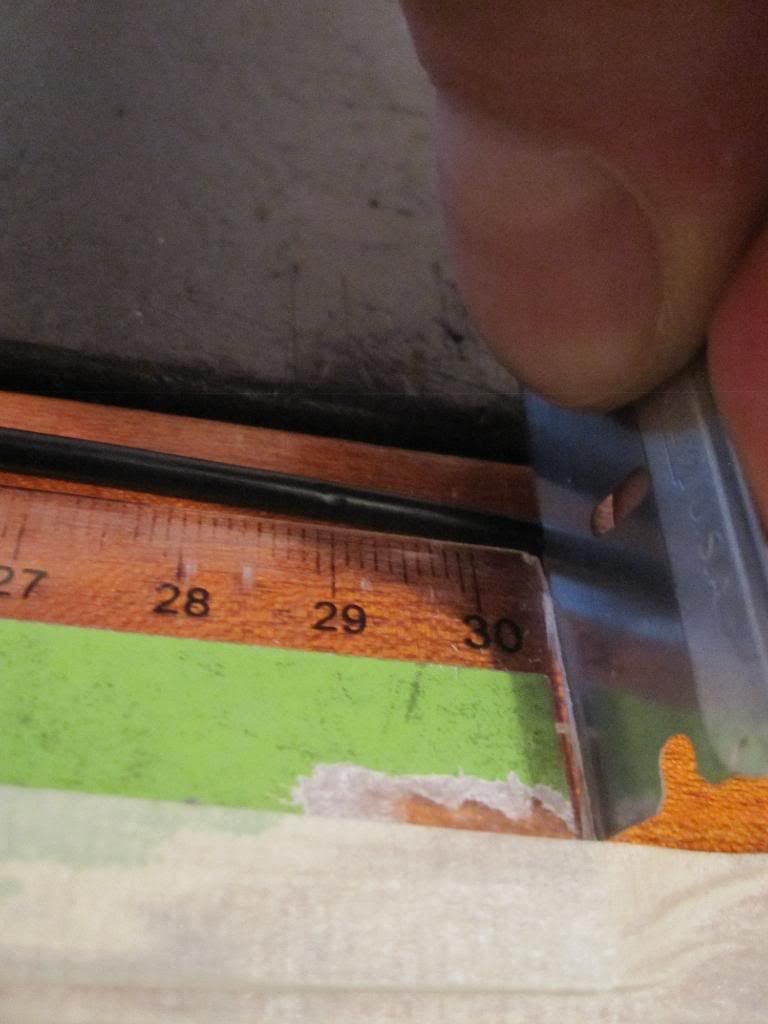
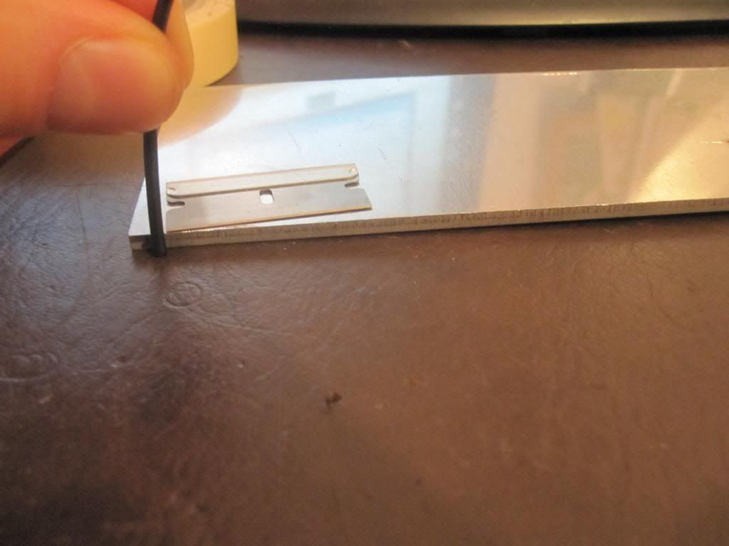
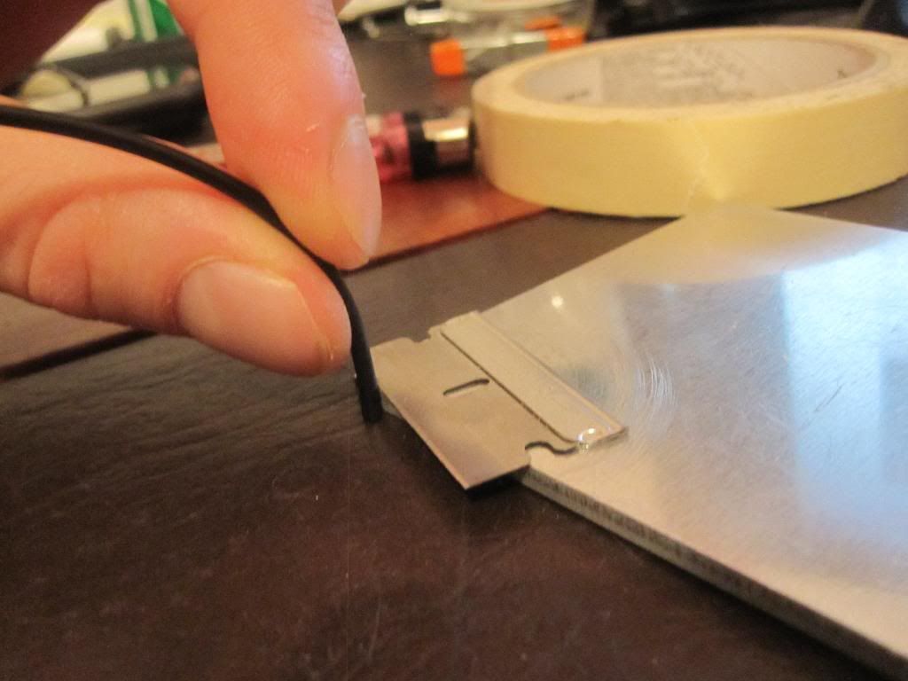
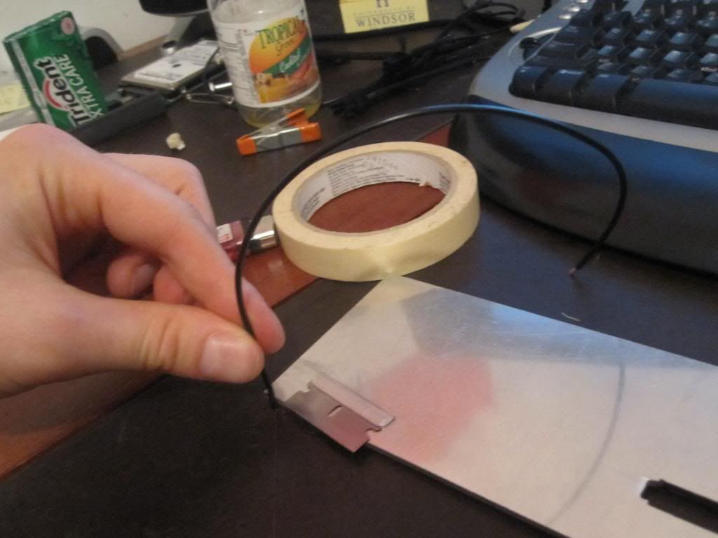
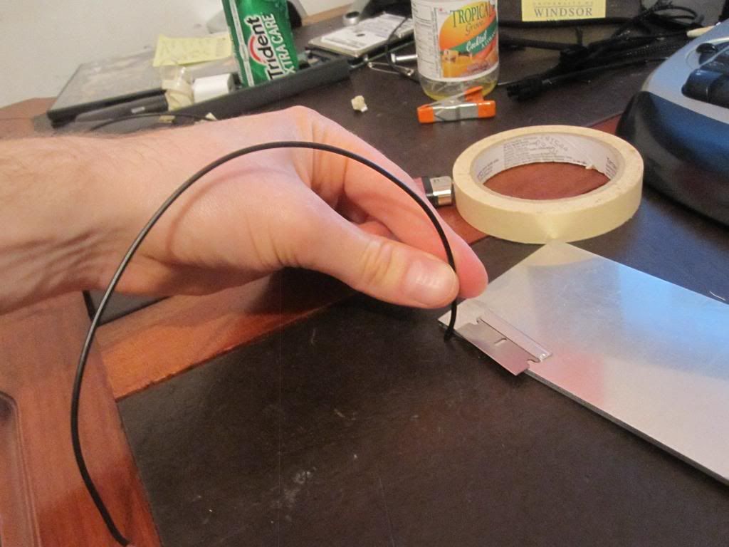
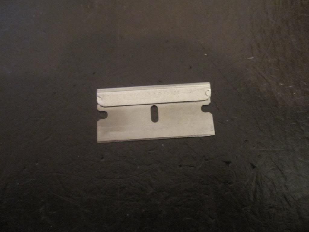
13. Razor blade (see pic)
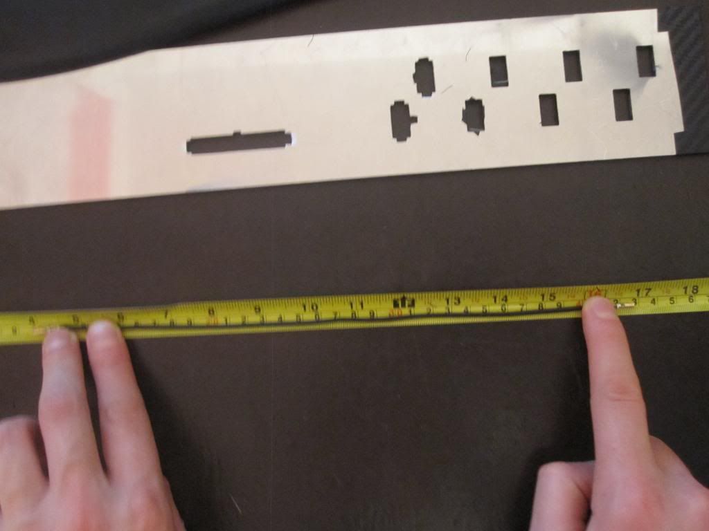
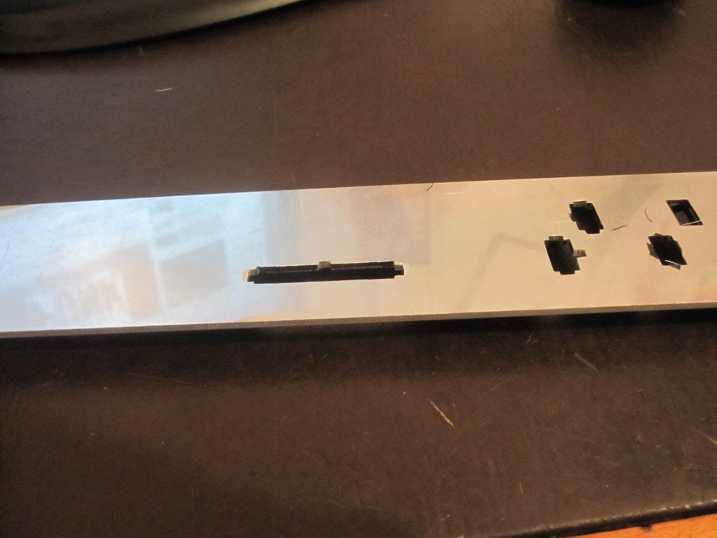
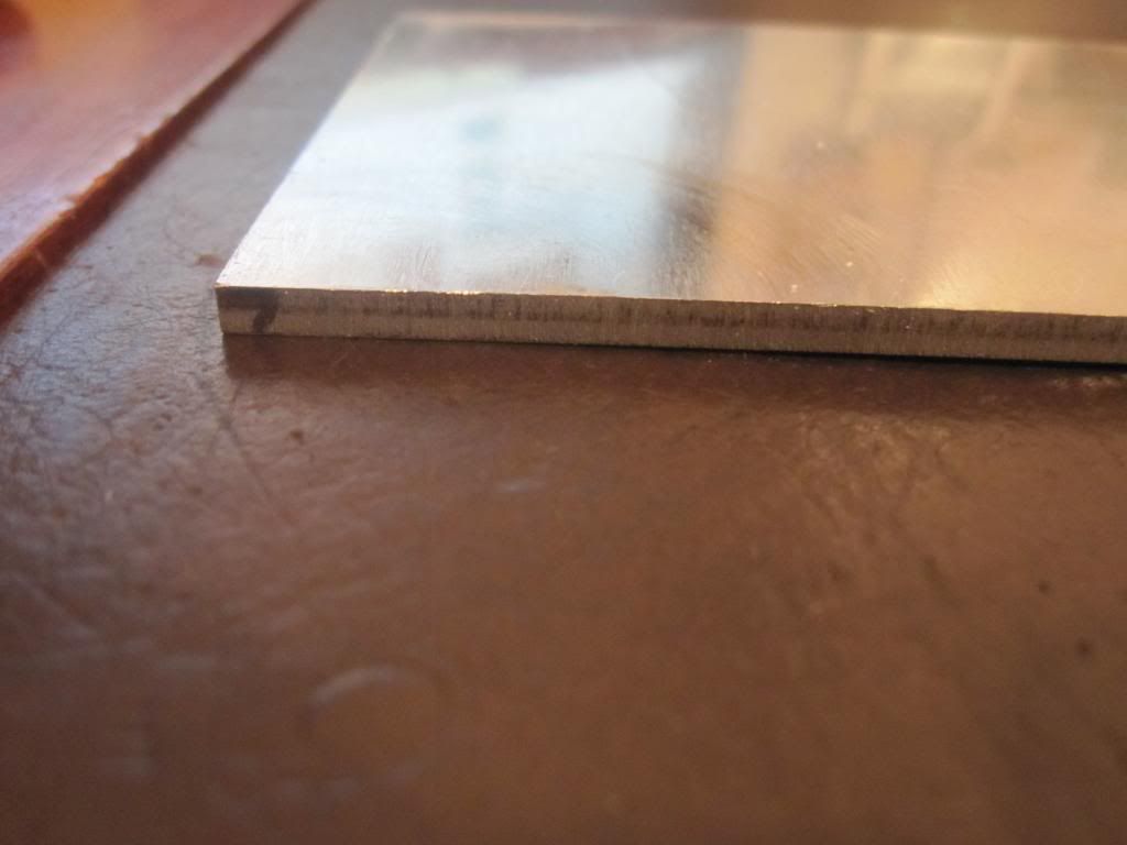
14. 1/8" (3mm) Aluminum or any other material 1/8" thick) atleast 3" x 5" in dimensions
15. ATX Connectors (8pin EPS, 4pin P4, 6 pin PCI-E, 8 pin PCI-E (or 6+2pin), 24 or 20 Pin ATX Mobo)
16. Flat working area
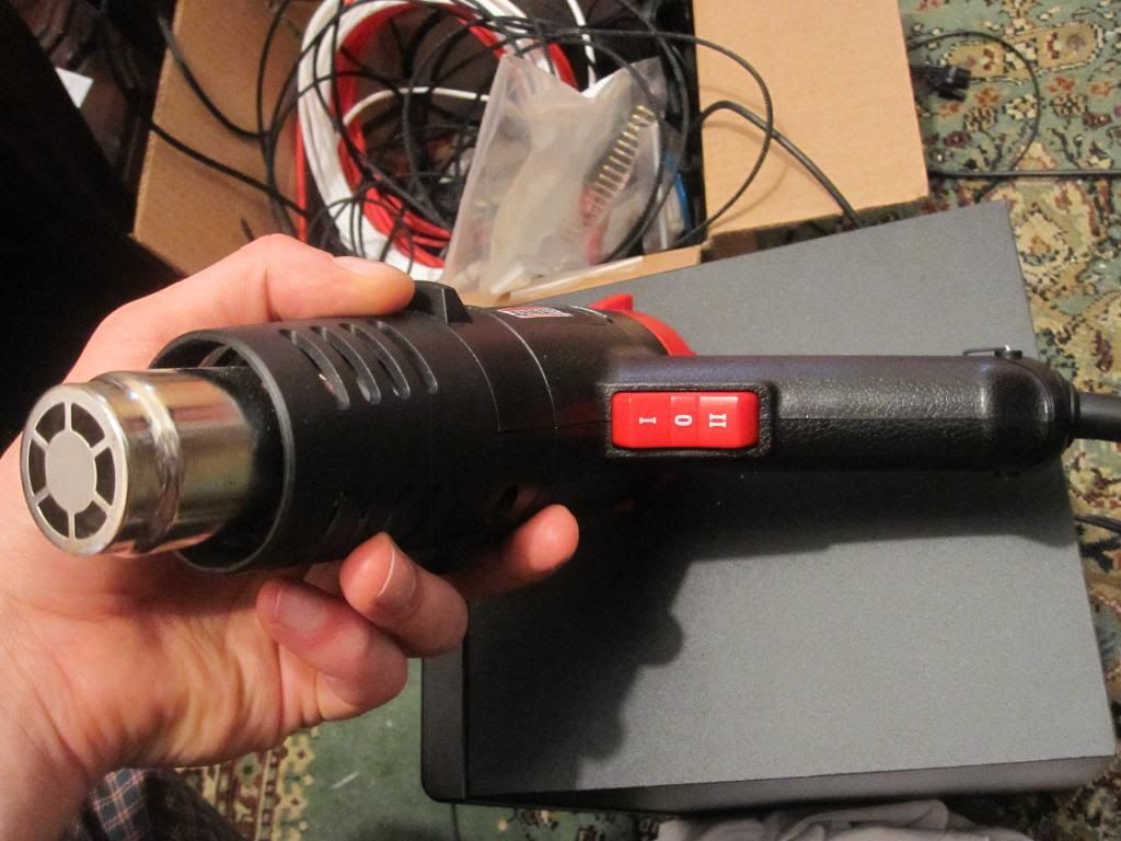
17. Heat Gun (with low and high setting)
18. ATX Pin remover
19. A LOT OF PATIENCE!!!!!!! and time (when you master it, it becomes very easy)
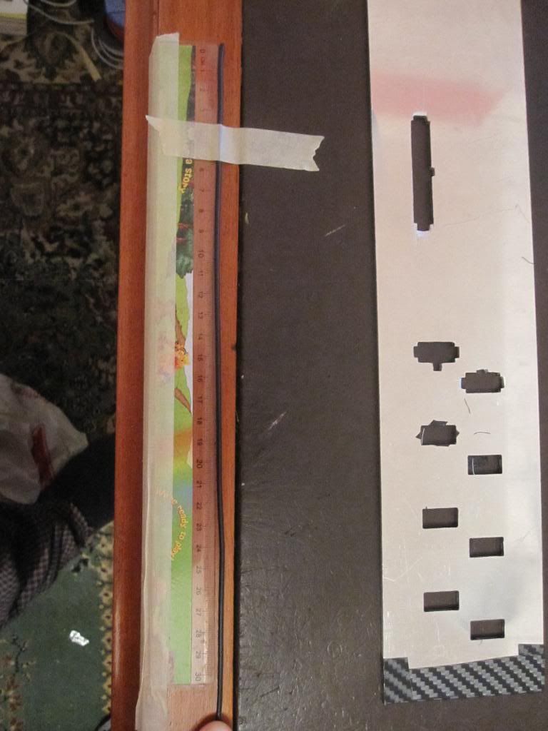
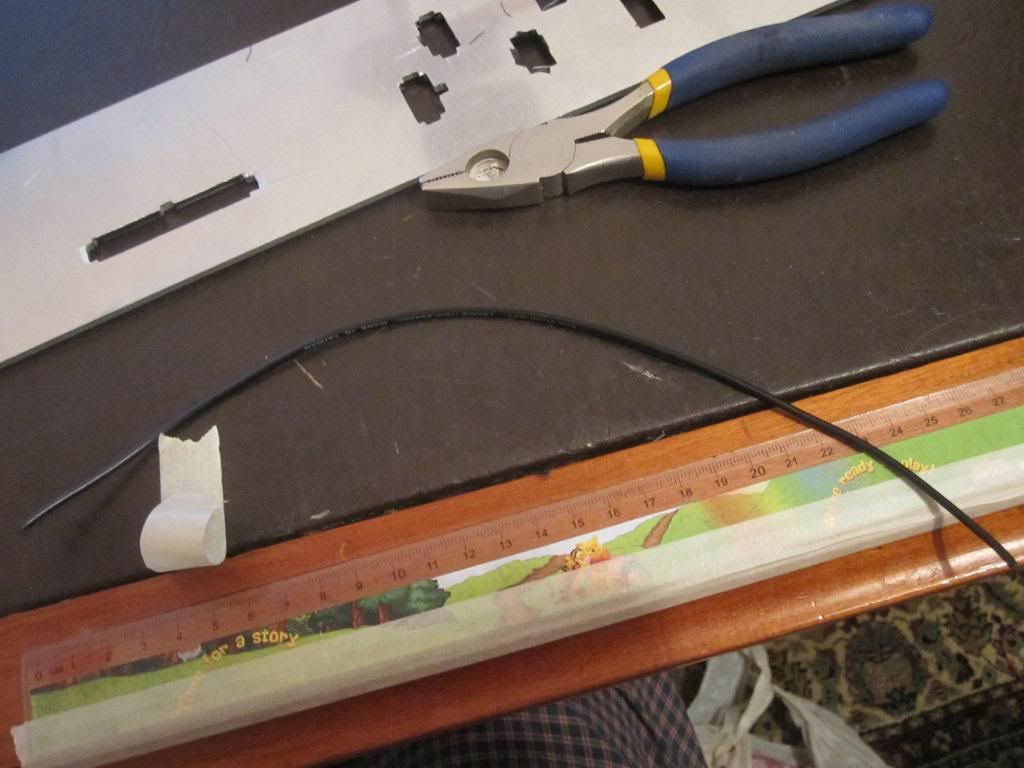
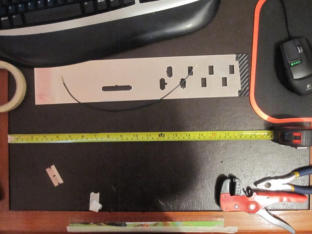
Here are some pics of the tools I used...
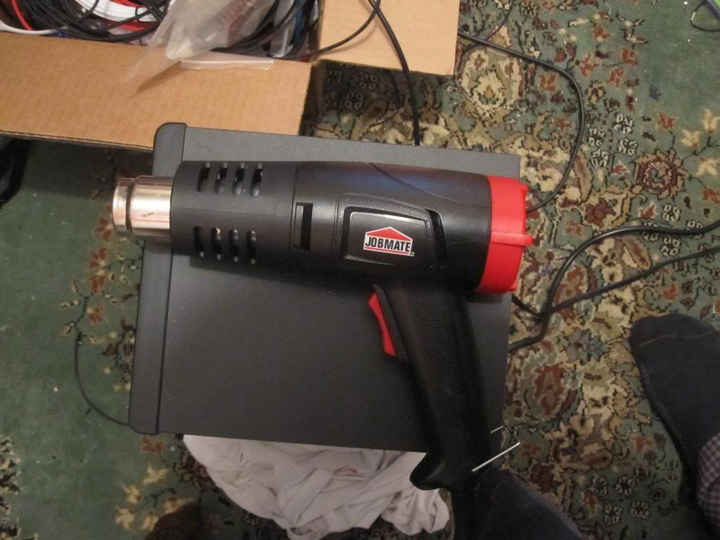
High and low settings (high heat, low heat)
MDPC-X SINGLE SLEEVED CABLED AT THEIR FINEST
I received a request from a member of another forum for a guide on how to single (individually) sleeve your power supply or custom made cables with MDPC-X sleeving and heatshrink. This is my technique and it can be done many other ways
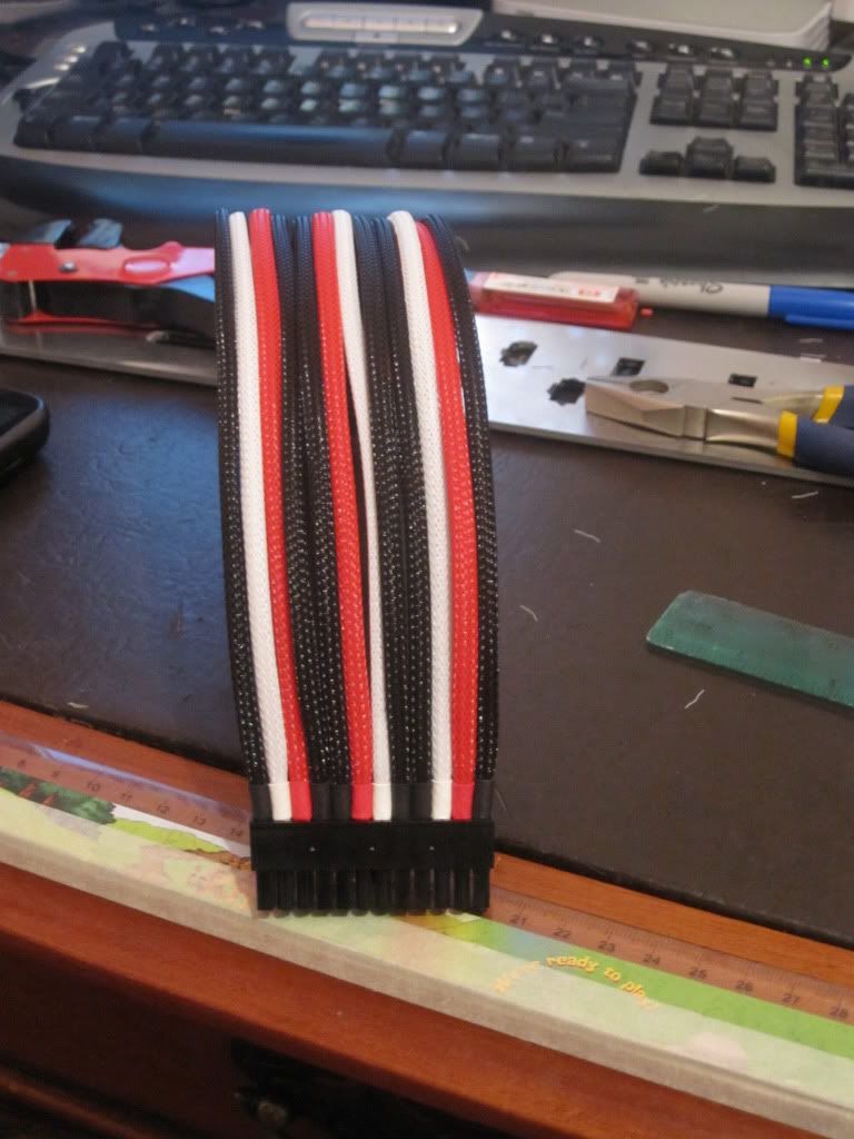
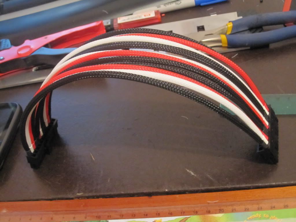
I find this works well and gives good results (all the heatshrink lines up perfectly).I have used these techniques on my FERMI 2 build, CHECK IT OUT!!!!!
First you are going to need some tools and tools, heres the list:
1. MDPC-X small sleeving
2. MDPC-X Pre-cut heatshrink (15mm long)
3. 18 Gauge Wire ( I used automotive stuff - seems to have a thicker pvc wall than the regular stuff)
4. ATX male and/or female connector pins
5. ATX pin Crimping tool
6. Ruler
7. Masking tape
8. Pliers (that can cut wire)
9. Wire stripper (preferably like the one i have but standard ones are fine)
10. Measuring tape
11. Good pair of scissors (dont use a cheap pair if you want good results $15-40)
12. Lighter
13. Razor blade (see pic)
14. 1/8" (3mm) Aluminum or any other material 1/8" thick) atleast 3" x 5" in dimensions
15. ATX Connectors (8pin EPS, 4pin P4, 6 pin PCI-E, 8 pin PCI-E (or 6+2pin), 24 or 20 Pin ATX Mobo)
16. Flat working area
17. Heat Gun (with low and high setting)
18. ATX Pin remover
19. A LOT OF PATIENCE!!!!!!! and time (when you master it, it becomes very easy)
Here are some pics of the tools I used...
High and low settings (high heat, low heat)
Last edited: