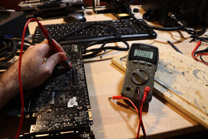
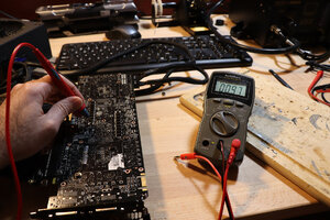
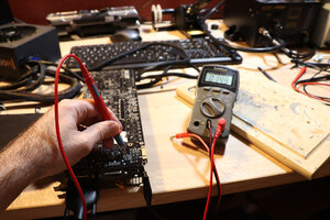
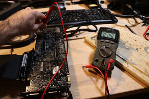
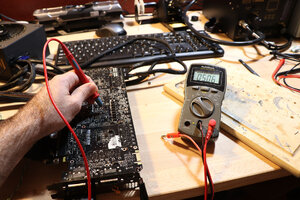
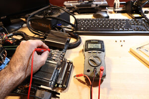
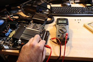
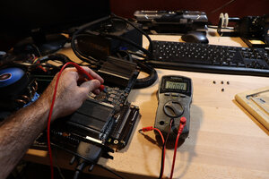
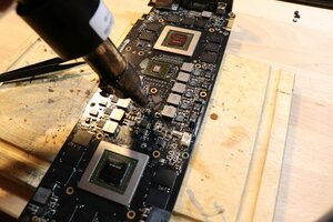
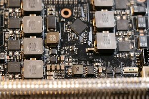
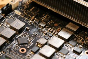
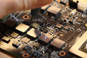
Graphics Card Necromancy: Resurrecting a Dead GTX 690

RazorWind

Supreme [H]ardness
Joined
Feb 11, 2001
Messages
4,646
Ok, so, just to be clear, I'm totally aware that this card sucks, SLI sucks, I'd do better buying a 2080 Ti, I could just buy a working GTX 690, repairing a graphics card isn't practical and so forth. I am doing this purely for my own education first, and amusement second. Seriously. This has been more fun and intense than any video game could ever hope to be, so far.

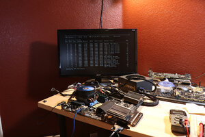
Now... I've always been a sucker for dual GPU cards. I've never owned one, because they're not terribly practical, but I've always thought they'd make a neat wall hanging mounted in a shadow box with the heatsink off and the dies exposed. So I went searching for a dead one, and I got lucky and was able to score not one, but two GTX 690s for a total of $50 shipped to my door. I'm ashamed to admit that I neglected to take photos of them when they arrived, but they look pretty much like you'd expect a dead video card from 2012 to look.

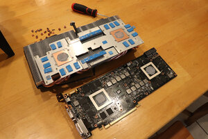
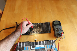
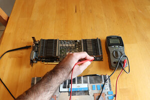
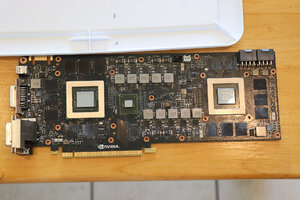
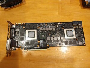
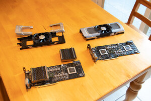
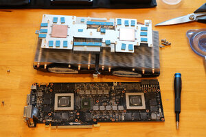
Having basically nothing to lose, and inspired first by my family of electrical engineers, and second by messieurs Rossmann and Buildzoid, I then decided that I might as well try and get one of them working. We'll call them Card A and Card B. Here's what they look like now. Card A is on the right, B on the left.
IMG_4217.jpg

Card A looks pretty good. There was no visible damage that I could see, so I plugged it into an old AM3 board, but unusurprisingly, I got no picture. I took it apart, and started checking resistances. What I found is that both cores have a sane resistance to ground in the 10-15 ohm, range, but while one GPU's memory power plane has about 130 ohms to ground, the other one has a dead short. I tried all week to figure out where the short is, but I eventually ruled out most of the easily tested components, so I think there's a pretty good chance it's one of the memory chips.

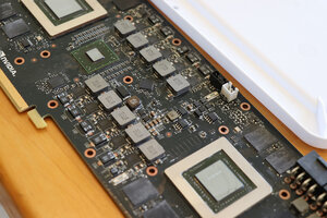
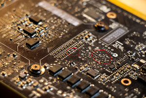
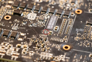
That brings us to Card B. This poor thing looked pretty haggard, with both corrosion damage and missing caps, as seen below. Nevertheless, both cores and memory planes show a sane resistance to ground in the 10-15 and 130ish ohm range respectively, so this is going to be our candidate for repair.
IMG_4218.jpg

IMG_4210.jpg

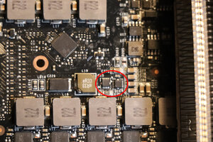
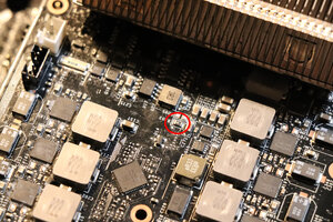
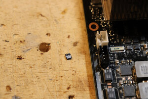
The most obvious problem is seen in the photo above. The component circled in red in that photo is not a cap, but rather a 10K ohm resistor, which is used to bias the enable pin on the card's 5V VRM. Without it, the 5V VRM doesn't power up, and thus most of the other VRMs also don't start up, as most of them require 5V power for their internal logic. What the photo fails to convey is that that resistor is only about 1mm long. Rossmann makes resoldering a component that small look easy, but allow me to assure you it's not, even with a hot air station. Eventually, as I was holding it with my tweezers, it went PING! and fucked right off to god knows where. I tried cannibalizing the same resistor from the really dead card, and it too eventually fucked right the hell off and disappeared in the mess on my workbench.

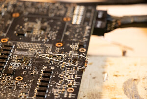
So, I dealt with the problem thusly:
IMG_4215.jpg

I had a spool of wire left over from my Xbox modding days, so I soldered two lengths of it to a 10K through-hole resistor, and shockingly (ha!), it worked! The card how has 5V power, which means that all of the VRMs I can find on it now power up, even if they're not 100% working. Obviously, I'll need to replace the dangling resistor with a real SMD one at some point, but this was good enough for diagnostic purposes, for now.

More to come later...
 
I expected to see a 690 in an Easy Bake Oven! Jk, this is the kind of stuff I love to read about. Hope you keep posting updates, regardless of the results!

Can a defective 690 still function as a 680? Depending on the damage of course.
 
I expected to see a 690 in an Easy Bake Oven! Jk, this is the kind of stuff I love to read about. Hope you keep posting updates, regardless of the results!

Can a defective 690 still function as a 680? Depending on the damage of course.
Thanks! I got sent to the field this week, so I'll have to wait until the weekend to do any more work on it. To answer your question, the answer is obviously "maybe," subject to exactly what the damage is. It's counterintuitive, but it seems that the GPU on the right, further from the display ports is a little more important than the one on the left, since it's that GPU's memory plane that's hooked up to a couple of the minor power rails that seem to be shared between both, whereas the other GPU doesn't seem to have this. So, I suspect it's possible to get the card to work as a GTX 680 if the failure were in the left GPU or its memory.

I also suspect that one could probably install some jumper wires to bypass a dead GPU and force the remaining power rails to enable, thus powering up the remaining, presumably good, GPU. Before I resort to anything that drastic, I'm hoping to just figure out which IC is bad on my card and replace it. I haven't given up hope that I can get both GPUs working yet, since the problem seems to be an issue of powering up all the VRMs in the right order.

In the mean time here's a few photos from the field. This is Port Aransas, Texas, where hurricane Harvey came ashore in late 2017. It looks way better now than it did then; just a handful of blue tarps still on the roofs.

porta_2019.jpg

And here's an air to air shot of a T-6 Texan II from NAS Corpus Christi that was doing touch and go's at Aransas County, a little ways up the coast.

t-6-3.jpg

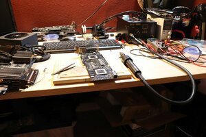
And a shot of my office for the week.
office.jpg
 
Well, Ill admit I dont understand a lot of the electrical engineer lingo, but I love seeing old hardware resurrected. Keep the updates coming!
 
The 690 was a hell of a nice card back in the day. Just a beautiful card. I owned a couple of them.
 
Thanks for the shots Razor, I love Port Aransas.. Been going there since I was a kid.

Cool card pics too obviously!
 
Thanks for the shots Razor, I love Port Aransas.. Been going there since I was a kid.

Cool card pics too obviously!
Thanks! I've flown over Port A probably hundreds of times, but I've never been there on the ground. It looks nice from the air, though, when it's not freshly obliterated by a hurricane.

I'm back from the field for a few days today, so hopefully I'll have some time to spend with the card this evening. I cheated a little, and bought a third, supposedly working, card from Ebay, which should arrive tomorrow. Having one that works properly on hand should be a big help with figuring out what voltages are missing from my patient card, and which components are suspect.
 
Alright guys, one step forward, two steps back. Enter, Card C...
IMG_4267_rsz.jpg IMG_4268_rsz.jpg

Cards A and B are Dell branded ones, whereas Card C is a PNY brand one. It seems to have some minor differences in terms of which components are used on it, such as different Vcore power stages and the doofy aftermarket heatsink, but it's otherwise identical to the other two.

I unpacked it, and plugged it into the test rig, and.... It worked!

IMG_4263_rsz.jpg IMG_4264_rsz.jpg

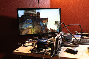
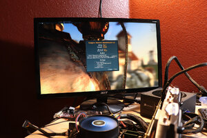
It took what I perceived to be an eternity to install the drivers, I guess thanks to the antiquated SATA 2 channels and FX-8350 in my test setup. It defaulted to having SLI enabled, so I turned it off and ran the Heaven benchmark with just a single GPU (for those wondering, the one nearest the display ports is the 'main' one, it seems). Score was ~1020, which seems... sane, I guess. Framerate seemed to range from about 30 up to high 50s. That doofy heatsink is pretty effective, though. After about 10 minutes, the active GPU leveled off at a reported 60C. I expected way worse.

Satisfied it worked properly, I quit out of Heaven, re-enabled SLI, and reran the benchmark. Perhaps unsurprisingly, the framerate was roughly double with SLI enabled, but then... the screen just went black. Crap. :(

I tried reseating the card in the slot, rebooting, resetting the CMOS, plugging the card into my main gaming rig alongside my 1080 Ti, but the new card now seems to be dead as a doornail, too. So now I have two patients.

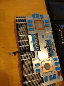
Having little to lose at this point, I pulled the funky Arctic Cooling heatsink off, to find this:

IMG_4269_rsz.jpg

Can you see what's wrong in this picture? What kind of horrible monster installs new thermal pads over the dessicated remains of old thermal pads?

To be continued...
 
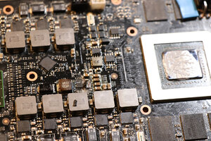
At this point, I should probably talk a little bit about how a graphics card works, as understanding this is really critical to any troubleshooting one might do. Most of the exposed circuitry on a modern graphics card is related to power, either for the GPU itself, its memory, or their related power supply circuitry. The GPU typically runs on a much lower voltage than the 12 volts supplied by the power supply, so the card has to have a series of converters, sometimes called VRMs or buck converters, to convert the 12V down to the 1 to 1.5 volts the GPU needs. In addition, the card also requires several other voltages to power the memory, display ports, BIOS chips and the voltage converters themselves, each of which requires a specific voltage, and thus needs dedicated circuits to produce it. I should also point out that you can quickly get a pretty good sanity reading on whether or not the memory and GPU core are by measuring the resistance across them. This won't tell you for sure that they're good or bad, but it will give you a pretty good idea.

An important thing to remember is that for each voltage, you'll need at least a few basic components, which are:
1. A controller IC of some sort.
2. Two or more switching transistors, which are usually MOSFETs. These are sometimes integrated together into a single IC, called a "power stage" or "power block." They can also be distinct components.
3. An inductor, which is typically the largest component in the buck converter circuit.
4. Capacitors, which help smooth out noise in the voltage caused by the switching of the MOSFETS.

I mention all this because you can pretty quickly narrow down the list of potential problems on an apparently faulty graphics card by taking a few resistance and voltage measurements from the terminals of the card's various buck converters.

So, let's step through some diagnostics on Card C, our newest patient:

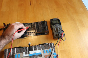
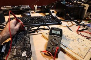
1. Measure the resistance across the GPU itself. You can do this by measuring from either side of the output inductors to any of the myriad ground points on the card. The IO cover plate is a convenient ground point. What you're looking for is a resistance of like 3 to maybe 50 ohms. Zero indicates a dead short to ground, which is bad. A really high value of say hundreds, or thousands also indicates a problem.
IMG_4271.jpg

2. Measure the resistance across the memory plane. You want to see something here in the tens to hundreds. Again, a zero indicates a dead short to ground, and a high value indicates some other horrific problem.
IMG_4274.jpg

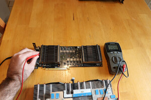
3. On multi-gpu cards, repeat 1 and 2 for the second GPU/memory.
IMG_4275.jpg IMG_4273.jpg


As we can see here, we have sane resistance on both GPU and memory power circuits. That's good. That means our problem is not a dead short, and probably isn't a totally lobotomized core or memory.
 
Last edited:
Since our resistance test did not raise any red flags, we need to test the voltages that are present on the card and see if any are missing, such as would explain why our card doesn't work.

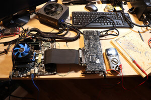
So, we hook it up to the motherboard thusly. You can totally do this without the use of the riser cable, but I find that makes it easier, especially if you're going to test with one hand and hold the camera with the other.
IMG_4277.jpg

Next, start the system up, and start taking measurements. First, check for 12V power. We obviously won't get very far without that.
IMG_4278.jpg

Next, test all the voltage rails. As a hint, if there's an inductor, that's probably related to a VRM, so you should test the voltage to ground on its terminals. I should also note, however, that there are probably rails where the inductor is integral to the controller IC, and you'll need to identify those and check them too. Many of these minor rails are produced little low dropout regulator ICs are little SOP-8 package chips with eight pins, about a quarter inch long.

We'll start with VCore, which is convenient to check at this empty pad on the back. That 0.88 is a little worrying, but the .97 is normal for the card when it's idling.
IMG_4279.jpg IMG_4280.jpg

And then Vmem. Looks good. 1.5 is spec.
IMG_4281.jpg IMG_4282.jpg

Now, we need to check all the low power rails, which all have to be present, but don't usually have great big arrays of chokes and MOSFETs. As a hint, look for ICs with eight pins. These might be BIOS chips, but they also might be small VRMs. You'll have to read the part numbers off of them and dig up data sheets to tell what they are for sure. If you're lucky like me, and work for your state's geological survey, you probably have access to petrographic stereo microscope, which makes that task SO much easier. I found 10X magnification worked the best.

Anyway, this mosfet on the back is convenient because it's powered by the 5V rail, but it produces the 1.8V rail (related to the PCI-E switch chip, I believe), so we can test for both of those on its various pins.
IMG_4283.jpg

Next, we flip the card over, and check some more on the front. Here's the 5V rail's inductor

IMG_4287.jpg

And the 12V power supply from the slot:
IMG_4286.jpg

And finally, the .95V rail. But wait, what's this? Zero volts? That's not good...
IMG_4285.jpg
 
Ok, at this point, we know that there is a problem with our .95 volt VRM, but we don't know why. Remember when I mentioned above before that a typical VRM has four major components (controller, FETs, inductor, caps)? That's useful here. We need to identify which components near that inductor where we measured zero volts are part of this VRM. You can do so by working backwards from the inductor with your multimeter in continuity or resistance mode. You should have some sort of FETs or a power stage directly connected to it nearby, and then a control IC connected to those near to that. Remember that some or all of these components may be on the opposite side of the card.

In our case, the two MOSFETs you see here are the connected to that inductor:
IMG_4288.jpg


And this control IC is connected to those, on the back of the card.
IMG_4208.jpg

Once we've identified the control IC and MOSFETs, we need to check each one for function, and for that, we need the datasheets.

I'm going to skip testing of the MOSFETs for the moment, because I can't read the labels on them without a microscope, and go straight for that control IC, which is an Intersil ISL6545.

If we look at the data sheet, we'll see that:

Pins 1, 2, 4 and 8 connect to the MOSFETs. We should have continuity to their various input pins, but no shorts to ground. Pin one is the one nearest that little dot in the upper right of the IC in the picture. - These all look good.

Pin 3 should be shorted to ground. - It is.

Pins 6 and 7 should have a non-zero resistance to ground. - It does.

Pin 5 should have either five or twelve volts supplied to it. - Hold up. We've only got about 1.6V supplied to that pin!

Some probing of test pads and following of traces around shows that our actual supply voltage for pin 5 comes to us through this, theoretically 0 ohm, resistor. In the photo, pin 5 is connected to its right side, and it should have 12V supplied to its left. Because it's a zero ohm resistor, we should 12V on both sides of it. Instead, we have 12V on the left, and only 1.6V on the right. Taking a resistance measurement across it gives us about 19K ohms. That's a lot more than zero. Because we have three cards, we can test on Card B and confirm that its resistance really should be zero.

IMG_4290.jpg


So, we've now identified a likely failed component, and we need to remove it from the board and replace it with a known good one. Luckily, we have a donor card to get one from...
 
Here's our donor board being prepared for surgery.
690_001.jpg

Heating up our good part. Getting a photo of this while holding the camera was... not easy.
690_002.jpg

Our zero ohm resistor, successfully removed from the donor board.
690_003.jpg

Here's our empty pad on Card C, ready to receive the good resistor...
690_004.jpg

And the new resistor, soldered into place.
690_005.jpg

At this point, I plugged the card back in and turned it on. There's good news and bad news. The good news is, we now have 12 volts at pin 5 on our ISL6545. The bad news is, the .95 rail is still dead. I'm not sure whether it's the MOSFETs or the control IC that's still bad, although the MOSFETs seem like a more likely culprit.

I'm unfortunately back in the field today, slowly eating and flying my way up the Gulf Coast on the taxpayers' dime, so it'll be Friday before I can test that hypothesis.
 
Nice read Razor, been following since the first comment so I just thought I'd just drop a comment to keep it going.

I build jets for a living, but could never get the EE part down pat. Enjoying this thread immensely.

You should check out Louis Rossmann who Razorwind named in the original post. He has an extremely informative youtube channel doing repairs on apple boards. You'll see what you're watching here alot, except RazorWind is slightly better at surface mount soldering :p
 
I build jets for a living, but could never get the EE part down pat. Enjoying this thread immensely.
Which part of the jets are you building? Not the avionics, I hope. Heh.

I got back from the field yesterday, and got back after my work on Card C.

A fresh look at the card showed me a suspiciously low resistance across the low side MOSFET on our .95V rail, so I removed the MOSFET from the card. As I suspected, the resistance seems to be much more sane across the pads with the transistor removed. Inspection of the removed transistor itself reveals a dead short across it from the source to the drain, so it looks like this was probably our real culprit.

With that in mind, I removed Card A's analogous transistor, and testing reveals it has about 8M ohms from the source to the drain, which is about what it should have. So, I went about soldering it into place on Card C's pads. Here's the good transistor, after removal.
IMG_4336.jpg

Before you can solder an SMD component, you really need to clean the pads and re-tin them, so that the new component will stick properly, and the solder doesn't turn into globs that bridge the pins together. I spent about two hours working on this yesterday, and used up the last six inches of my solder wick, but try as I might, I just could not get the last bits of solder off the pads. Through the magic of Amazon, I have some fresh wick on the way that should hopefully arrive today. Here's what it looked like when I gave up. Gross.
IMG_4337.jpg

Card A's pads look good enough to be reused without cleaning. This is what it should look like.
IMG_4338.jpg

Stay turned. I'm hoping it just a matter of using some fresh wick.
 
Alright, alright, kids!

The new wick arrived, and despite my wick-fu being weak, I was eventually able to clean the pads well enough to solder the "new" MOSFET onto them. Some tests with the multimeter confirmed it was making good contact, and all the resistances between the various pins and ground looked appropriate.

Here it is, still covered in flux residue. I accidentally knocked its buddy, the high-side MOSFET out of place while was working, so I pulled that one off and reinstalled it as well.
IMG_4340.jpg

After checking the resistances and find nothing obviously amiss, I plugged the card back into the test rig, crossed my fingers, and hit the button. Nothing happened for a few moments, but then...
.
.
.
.
.
.
.
.
.
.
.
.
.
.
.
.
.
.
.
.
.
.
.
.
.
.
.
.

Signs of life!
IMG_4342.jpg

Now, I need to clean the flux residue off and install a cooler on it so I can test the card for real. I'm kind of suspicious that maybe the Arctic Cooling cooler that came with this card may not cool that MOSFET well enough, so I may cannibalize Card A's cooler, since it clearly doesn't need it anymore.
 
I am enjoying this thread, RazorWind.
In case you run into DPC Watchdog Violation errors during your testing, please read my post in this link and then read that whole thread: https://forums.geforce.com/default/...vlddmkm-sys-after-385-69/2/?offset=23#5348541
I mention this in case you think there is a problem with the hardware you fixed. In this case, it's a driver bug that has never been fixed.
Thanks; I've not had that problem yet, but I'll keep it in mind. At least on my test rig, when the card works at all, it seems to work fine.


Anyway, the best laid plans of mice and men...

I was all set to install one of the stock Nvidia coolers on my freshly repaired Card C, when I discovered that the thermal pads I have on hand are too thin to mate the cooler to the card. I need thicker ones. So, I decided to go ahead and test with Arctic Cooling cooler, which still has usable pads. I cleaned the flux off with isopropyl alcohol and a toothbrush.
IMG_4343.jpg

IMG_4344.jpg

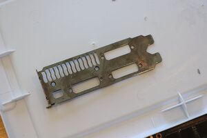
I also took the opportunity to clean the weird black sticky substance off of the expansion slot cover.
IMG_4345.jpg

I modified the cooler slightly to provide cooling for the other MOSFETs on the board that do not get cooled, even by the stock heatsinks. Here it is after I test fit it.
IMG_4347.jpg

After that, there was nothing left to do but boot the system up and test the card. So I plugged it in, and got windows started... And it worked!
IMG_4349.jpg

IMG_4353.jpg

At least, it worked for 20 minutes so. As I was typing my last post in this thread, I left it running Heaven, and after about 20 minutes, the screen went black again, at which point a measurment at the output of our .95V rail indicates 0.4V.

This suggests we have a recurring problem that takes out that 0 ohm resistor and also its related MOSFETs. A little probing with the multimeter afterwards suggests that the real culprit may actually the ISL6545 buck coverter controller for this rail, so I think the next step may be to cannibalize that from Card A as well.
 
Alright, Card C is back in business again - in fact I'm typing this post on the test bench with it running.

I measured the current draw on my .95V rail by applying 12V with my bench power supply, and determined it's drawing about 2 watts, which should be well within the range that a 0805 SMD resistor can handle. I had a hunch that I may have been damaging the zero ohm resistors when I'd remove them from the donor board, so I replaced the failed resistor with a jumper I made out of a little piece of the leg of a through hole resistor. I then reassembled the card, and it seems to be working now, although I haven't tried to make it run any games yet.
I guess I spoke too soon. The card made it through 20 minutes of Mass Effect 2, with the only obvious problem being that the FX-8350 in my test rig isn't fast enough to drive it past about 45 FPS in that game. It pegs out one core at 100% and the rest are idling. Neither GPU even goes into boost.

Then it died again, pretty spectacularly, when I tried to run the Heaven benchmark, with the high side .95V mosfet actually catching fire. It doesn't appear to have damaged anything else, luckily, but I have to wait for slow boat shipping from China for replacement MOSFETs to work on it any more, since the usual suspects like DigiKey and Mouser don't carry these. After disassembly, this is what I found:
IMG_4354.JPG

That's a little piece of ceramic MOSFET casing on top of the choke, there.

I'm doing some more reading now about what can cause this, but it seems like one of the main potential causes is that the voltage supplied to the gate pin of the MOSFET is too low, and the MOSFET isn't turning all the way on. When this happens, you a get current through it, but because it's not fully switched on, the resistance is high, which causes it to heat up, and eventually melt or burn. This can be caused by a few different things, but one of the most likely ones appears to be a faulty capacitor in what's called the "bootstrap" circuit. This is basically a circuit that is guaranteed to be a little lower voltage than the power supply for the control IC, but higher than the required voltage to switch on the high side MOSFET. This bootstrap voltage is what's supplied to the MOSFET to get it to switch, so it's low, you get the behavior we see here.

At least, that's one possible explanation.
 
Alright, an update. I had to leave for yet another work trip today, and I didn't have time to take photos but I spent some time yesterday on this.

Card C is dead, probably permanently. If you look in the photo in my last post, you can see the burned remains of the high side MOSFET. What you can't see is that it got so hot that it welded itself to the traces on the board and lifted the traces off the board. Try as I might, I can't remove it. It may be possible to frankenstein a new MOSFET onto the board using wires, but I don't have high hopes. I'm sort of tempted to ebay a fourth card, but the supposedly working one dying left a bad taste in my mouth.

So, I turned my attention to Card B, which is still the one we're hoping to actually fix. You may remember that this card arrived in pretty rough shape, with numerous components broken off of it, so I painstakingly unsoldered about half of the missing components, mostly ceramic caps, from Card A and then soldered them on to the proper places on Card B. After a couple of hours, I'd successfully completed the ones for the PCI-E finger, most of the memory chips, the PLX bridge, and the 10K resistor I bodged earlier in this thread.

Unfortunately, it still doesn't work. As best I can tell, the problem lies somewhere in the control circuits for the number 2 memory rail. Maybe 5-10 percent of the time, when the system is switched on, the number 2 memory rail will power up, but instead of the 1.55 volts it's supposed to make, it's producing 1.39, which I think may not be enough to power the other minor rails it also powers. As a result, the card doesn't post. One thing I've noticed is that the VRM for this rail (and the matching #1 memory rail) has some transistors attached that seem to control voltage supplied to the controller's enable pin. I spent a couple of hours trying to figure out how that circuit works, but I eventually had to give up and make dinner, and that's where I'm at. There doesn't seem to be any damage to either circuit, but I can't figure out what they're connected to on the card that tells the transistors to turn on, and apply the enable voltage to the controller. Every once in a while, they work, and the memory rails turn on, but just every once in a while. It does seem to be heat related - if I use the hot air station to heat the card up, that seems to increase the likelihood of it sorta working.
 
Good gravy. I've worked in labs before that would have *killed* for someone of your caliber to help them keep old equipment controller cards and the like alive. You should be proud of these efforts at GTX 690 necromancy; at the very least it's a great way to dig into the root problems that cause these things to fail. I'd love to see you grab a bunch of for-parts eBay kit and try to make that work in the future, too.
 
Good gravy. I've worked in labs before that would have *killed* for someone of your caliber to help them keep old equipment controller cards and the like alive. You should be proud of these efforts at GTX 690 necromancy; at the very least it's a great way to dig into the root problems that cause these things to fail. I'd love to see you grab a bunch of for-parts eBay kit and try to make that work in the future, too.
Thanks, man. I'm not by any means an expert at this, but it's been a really interesting experience for me, so far. I'm stoked that others are enjoying reading about it.

If you liked this, you may think this is interesting, too.
https://hardforum.com/threads/phoenix-rebuilding-a-unique-airborne-sensor-package.1858333/

I'd love to be able to revisit that project, but there's a pretty major software development effort required to finish the job, and our funding structure is such that I can't just do that speculatively. I'm sort of thinking of just doing it anyway over the summer, though.

Anyway, I've spent a little more time with Card B since my last post. I don't have a lot of progress to report, other than that, for reasons I don't fully understand, the number 2 Vmem rail now powers up every time. It's still only producing 1.39 volts, though. I think the next troubleshooting step may involve removing the seven or eight resistors from the board and measuring them, and then removing the corresponding ones from Card C and comparing them. I have a feeling one may be out of spec for some reason.
 
I have been slowly learning electronics by rebuilding and repairing 1968-1979 stereo receivers. I still have a long way to go, so thank you for this thread. I find it inspiring to have a glimpse into the minds of professionals :)
 
I have been slowly learning electronics by rebuilding and repairing 1968-1979 stereo receivers. I still have a long way to go, so thank you for this thread. I find it inspiring to have a glimpse into the minds of professionals :)

You should make a thread about it! I think we have an audio section on here, right? That sounds pretty cool. I should probably clarify that I am not a professional at this. This is a hobby for me, too, and the photos you see are of the inside of my home.

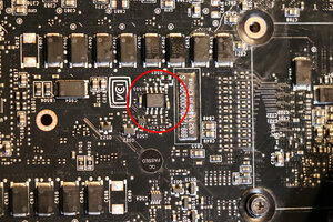
I'd been working like a dog the last couple of weeks, but I finally had some time to spend on this yesterday. I had been pretty stumped as to why my memory rail only produces 1.39 volts. The circuit that supposedly controls this is pretty simple - it uses some resistors to control the voltage supplied to a pin on the control IC. It boils down to using the resistors to step the voltage from the phase down from the actual supplied voltage to 0.6 volts, which the astute observer will note is the standard drop across a silicone diode. So, it seemed like my problem was that the resistance on the installed resistors was out of whack. So I unsoldered most of them and checked against Card A's resistors, and they're all fine. Another possibility is that I had a partial short through some component. I sat there looking at it for a while, and then I noticed this:

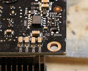
cardc_missing_cap.jpg cardb_missing_cap.jpg

Card C on the left, Card B on the right. Can you spot the difference?
 
Card C has a capacitor that card B does not have and card B has a resistor that card C does not have.
 
Card C has a capacitor that card B does not have and card B has a resistor that card C does not have.
Very good! The missing resistor on Card C is actually intentional (you can see it hanging out in no mans land to the upper left of the controller), but the missing cap on Card B is not. So, I swapped the corresponding cap from Card A on there.

Unfortunately, it didn't fix the problem. I still had 1.39 volts from the #2 Vmem rail. As I probed around that circuit, I discovered that the missing cap seems to be there for the purpose of stabilizing the gate drive on that transistor you can see in the photos. Oddly, though, on Card B, we only had 35 ohms to ground on the gate pin (near left), as opposed to about 4500 on the other two cards. This would cause the transistor to fail to switch on, as it's basically a short that keeps sufficient voltage from making it to the gate pin. It appears the purpose of this transistor is to help adjust the resistance to ground on our controller's feedback pin.

Then, tragedy struck. As I probed the various points in that area, I looked away from the board to my multimeter for just a moment, and as I did, one of the probes slipped, and touched... something with more than 1.39 volts. There was a spark, and a puff of smoke from the opposite (front) side of the card, and the system shut down.

Now,on one of the 12V power planes (it has one for each 12V power connector, plus the PCI-E bus), there's about 12 ohms resistance to ground, and zero ohms to the #2 GPU power plane. There should be 2500 to 3000 ohms on all of them, if the other cards are a reliable indicator. :(

Closer inspection reveals that two of the five power stages on the #2 Vcore VRM now have a nearly dead short, and my attempt to remove one with hot air resulted in it coming unsoldered from the GPU side, but lifting the trace for the ground plane, which it seems to have welded itself to. Two of the five power stages on the #1 Vcore VRM are also suspect, but I think they may be OK.

I don't think I'm going to be able to repair this. These power stages have a lot of pins, and I suspect that, given that this took 12 volts on the chin, there's probably more damage to the internals of the card than just this. I may give repairing Card C again a shot, but at this point, I'm otherwise out of potentially repairable cards.

I did ebay a fourth 690, because I decided that, after all this work, I want to end up with a working one, one way or another. I also found a disturbingly good deal on another, different, dead graphics card that I may make a separate thread about once it arrives in a couple of weeks. It's apparently coming to me in Texas all the way from Israel! That new card is pretty special, and it would be difficult to find another that isn't quite expensive, so I may also need to find some cheap cards to practice on before I try to fix it. Ebay doesn't seem to be the place for this. Anyone selling a dead graphics card seems to want between 50 and 100% of what a working one would cost, which just doesn't seem right, given how difficult they are to repair, if they can be repaired at all.

Would it be considered kosher to post a WTB - Your dead graphics card in the FS/FT forum?
 
Kosher? Heck, I think a lot of people here would be happy to unload dead cards for beer money.
 
You should make a thread about it! I think we have an audio section on here, right? That sounds pretty cool. I should probably clarify that I am not a professional at this. This is a hobby for me, too, and the photos you see are of the inside of my home.

I'd been working like a dog the last couple of weeks, but I finally had some time to spend on this yesterday. I had been pretty stumped as to why my memory rail only produces 1.39 volts. The circuit that supposedly controls this is pretty simple - it uses some resistors to control the voltage supplied to a pin on the control IC. It boils down to using the resistors to step the voltage from the phase down from the actual supplied voltage to 0.6 volts, which the astute observer will note is the standard drop across a silicone diode. So, it seemed like my problem was that the resistance on the installed resistors was out of whack. So I unsoldered most of them and checked against Card A's resistors, and they're all fine. Another possibility is that I had a partial short through some component. I sat there looking at it for a while, and then I noticed this:

View attachment 158856 View attachment 158857

Card C on the left, Card B on the right. Can you spot the difference?

It looks like a missing SMD near the transistor. SMD capacitor? I don't quite understand how to identify blank SMD components. Also C501 looks really rough.

Thank you for explaining your thought process so plainly, that makes perfect sense to me :) It is the same process for troubleshooting old amps, only the components are much larger and therefore easier to work with. Also some manufacturers made amazing service manuals, especially Sony, which went so far as to explain what each circuit does.

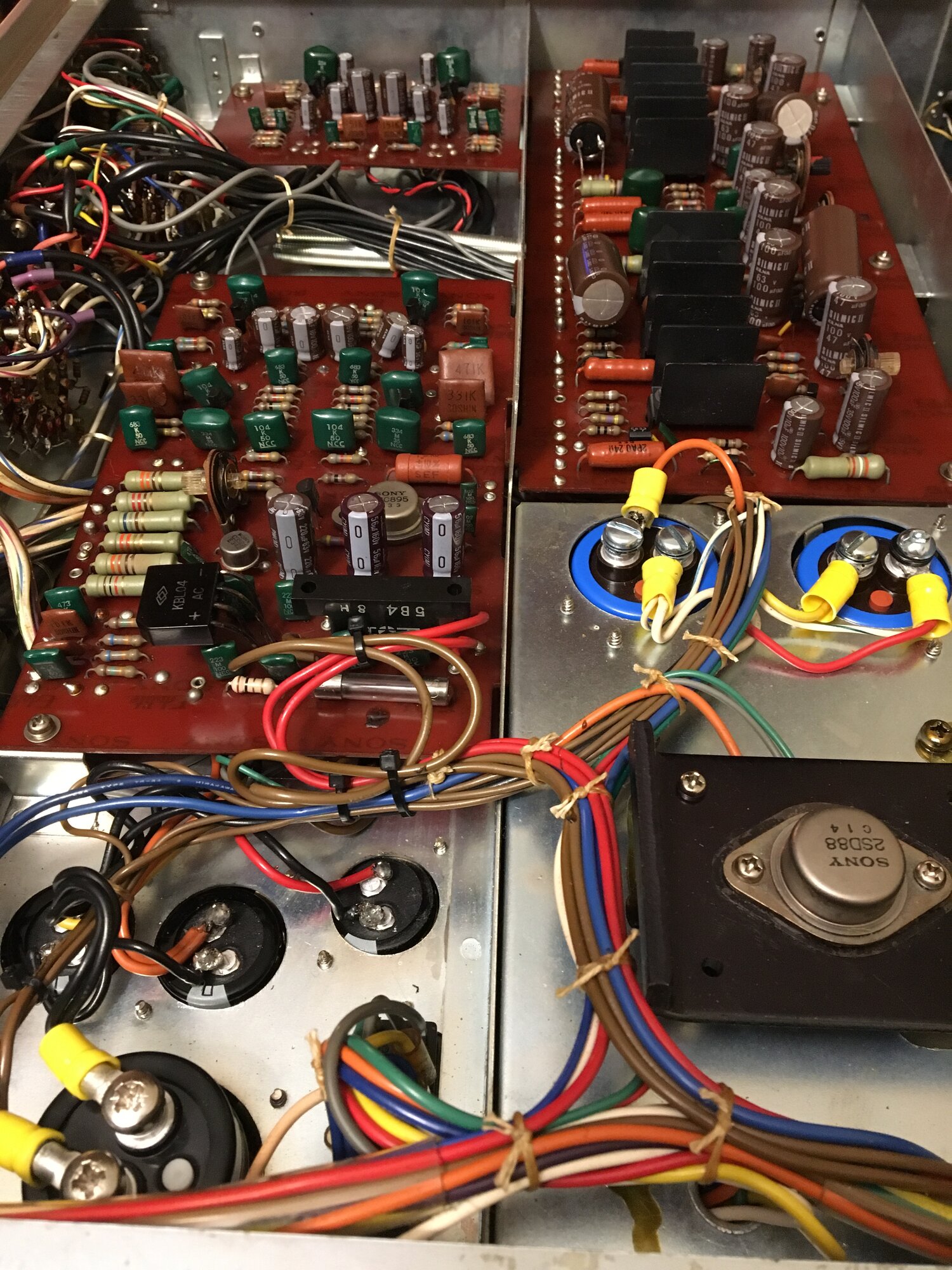
Here is a Sony STR-6120 that I have been working on. I blew it up a few times when I installed a filter cap strangely marked stripe positive instead of neg in reverse polarity and then again with some bad output transistors, but I managed to fix it after some troubleshooting. I've changed all the electrolytics because caps from 1969 can be very dried out. Maybe I'll do a thread on my next project :)


IMG_1648.JPG
 
It looks like a missing SMD near the transistor. SMD capacitor? I don't quite understand how to identify blank SMD components. Also C501 looks really rough.

Thank you for explaining your thought process so plainly, that makes perfect sense to me :) It is the same process for troubleshooting old amps, only the components are much larger and therefore easier to work with. Also some manufacturers made amazing service manuals, especially Sony, which went so far as to explain what each circuit does.

Here is a Sony STR-6120 that I have been working on. I blew it up a few times when I installed a filter cap strangely marked stripe positive instead of neg in reverse polarity and then again with some bad output transistors, but I managed to fix it after some troubleshooting. I've changed all the electrolytics because caps from 1969 can be very dried out. Maybe I'll do a thread on my next project :)


View attachment 159304

Neat! Which caps are the ones you replaced? The two big ones on the left with the solder blobs? Or did you replace all of them?

But yeah, you should make a thread about that.
 
Neat! Which caps are the ones you replaced? The two big ones on the left with the solder blobs? Or did you replace all of them?

But yeah, you should make a thread about that.

All of the electrolytic caps are new. I replaced the original grey Elna Silmics with new brown Elna Simic II. They are specifically for audio. Solder blob ones are actually TDK Epcos snap in power supply caps, which are very low ESR but hard to solder wires onto compared to other types. I installed terminal caps for the rest of the big power supply filter caps. BC Vishay or Mallory brand typically.

Anyway, sorry to hijack :)
Ehh, I think we're done here for a little while. Hijack away.

That's wicked cool, but man I bet that took forever. I hate desoldering through-hole components - I can never get all the old solder out.

How did you desolder the old ones? One of those solder sucker things?
 
Even though you haven't had the success you wanted with these cards, this thread has been a great read. I was truly looking forward too every update.
Here's to finding another dead card and bringing it back to life.

I did have an advantage with finding the differences between the two boards above. I have done SMT and rework of boards for nearly 19 years.

Thanks; I'm glad you enjoyed it - I know I did, and I feel like I learned a lot, even if I couldn't save any of these. I do wish I had started working on something less complex, though, like a maybe 680. I feel like I should have been able to save Card C.

I went back to eBay and found some more cards to work on yesterday night that were more reasonably priced. I bought two identical dead ones, and I already have a working third one to look at, so I should have both a working one, a repairable candidate, and a card for parts. I may make a new thread once those arrive, since they're not 690s.

I do have a question for you, since you do this for a living. Card A has a dead short to ground on its #2 Vmem rail, but there is otherwise nothing obviously wrong with it. If you had this card in your hands, how would you go about diagnosing the short?

Here's what I've tried so far:
1. Visual inspection - I can't see anything obviously wrong with it.
2. Testing resistance to ground at various points - with a regular multimeter, I just get 0.000 everywhere.
3. Supplying a current to the rail at the operating voltage, and feeling for parts that get warm - none get obviously warm; it draws about 8 amps at 1.5V
4. Doing as #3, but covering the board in isopropyl alcohol and looking for bubbles or vapor - I don't see anything.
5. Removing the largest components that commonly fail, like the power stage mosfet thing
6. Supplying current to the board and looking for voltage drop between various points in the millivolts range. I get 0.000 mV everywhere.

Given that, what would you try next to find the short?
 
Ehh, I think we're done here for a little while. Hijack away.

That's wicked cool, but man I bet that took forever. I hate desoldering through-hole components - I can never get all the old solder out.

How did you desolder the old ones? One of those solder sucker things?

I can completely redo a couple receivers in an evening. I stand the receiver up on its side. I heat one pin from the back of the board and while pushing against the top of the cap from the side in the direction of the cold pin. Then I reverse. This alternating rocking and heating pops out the cap in a few seconds. Then I tap on the solder points with the hot iron until there is a whole through the old solder. Pop in the new cap, bend the wires out to hold it in, then solder and trim off the access wire. Only needs a tiny bit of new solder to blend with the old.

I have only used a solder sucker for an op-amp IC. Rows of pins doesn't work with my rocking method.
 
Thanks; I'm glad you enjoyed it - I know I did, and I feel like I learned a lot, even if I couldn't save any of these. I do wish I had started working on something less complex, though, like a maybe 680. I feel like I should have been able to save Card C.

I went back to eBay and found some more cards to work on yesterday night that were more reasonably priced. I bought two identical dead ones, and I already have a working third one to look at, so I should have both a working one, a repairable candidate, and a card for parts. I may make a new thread once those arrive, since they're not 690s.

I do have a question for you, since you do this for a living. Card A has a dead short to ground on its #2 Vmem rail, but there is otherwise nothing obviously wrong with it. If you had this card in your hands, how would you go about diagnosing the short?

Here's what I've tried so far:
1. Visual inspection - I can't see anything obviously wrong with it.
2. Testing resistance to ground at various points - with a regular multimeter, I just get 0.000 everywhere.
3. Supplying a current to the rail at the operating voltage, and feeling for parts that get warm - none get obviously warm; it draws about 8 amps at 1.5V
4. Doing as #3, but covering the board in isopropyl alcohol and looking for bubbles or vapor - I don't see anything.
5. Removing the largest components that commonly fail, like the power stage mosfet thing
6. Supplying current to the board and looking for voltage drop between various points in the millivolts range. I get 0.000 mV everywhere.

Given that, what would you try next to find the short?

Sorry, I never got into debugging much. My best guess is internal damage, possibly a broken or fused trace. I've seen internal board damage from things shorting, ran the board through X RAY and there it was. We have a nice X Ray machine that allows us to "go around" the board to see just about every angle.
I know enough to follow along with what you have written but not much beyond that. I am just a peon for the most part.
The steps you have taken to trouble shoot look solid to me from the little debugging I have done over the years though.
Wish I could offer more help.
 
Ok, so remember how I said I ordered a fourth, ostensibly working, card, so I'd at least end up with one that works?

This arrived in the mail the other day. We'll call it card D. I made the dubious decision to buy it from the same seller I bought card C from, who somehow had gotten his hands on forty of these things, with these funny Arctic Cooling coolers.. I assume that means he bought old hardware from a mining operation, although I would not have imagined the 690 would be profitable for that, even back when it was new.

Anyway, here it is, after I pulled the heatsink off. As we can see, the same horrible monster installed this heatsink as the last one, and didn't even have the courtesy to clean of the dessicated remains of the old thermal pads.
IMG_20190508_200222053.jpg IMG_20190508_200226093.jpg

So, I installed it in my test rig and fired it up...

It worked! I'd had Card C installed before, so windows detected it as the same card and was perfectly happy. I started up Heaven, and let it run for 10 minutes or so, everything seemed normal, so I started the benchmark. But then, after another 5 minutes or so, and 3/4 of the benchmark, the screen went black. I said some words.

I gave it a few minutes to cool down, and started it up again, but to my surprise, the system actually posted and worked. So, I let it boot, and ran the Heaven benchmark again. This time, though, the screen went black after just a couple of minutes. Now, it was my suspicion at the time that the issue may have been heat, having seen how the seller installed the cooler. The Vcore VRM's power stages on this card have an overtemperature warning feature that can alert their controller that they're overheating and need to shut down. Given how much thicker the thermal pads are, and how slapdash the installation of the cooler was, it would not have shocked me to find out that the cooler was not cooling them as well as nvidia's stock cooler. Credit where credit is due, nVidia's coolers usually seem pretty well thought out, even if they don't blow us away with low temperatures.

So, I swapped Card A's stock nVidia cooler onto Card D, plugged it in, and tried again, but to my shock and horror, this time, I got no picture. :(

I think you all know where this is headed...
 
I did the same diagnostics on Card D as I did on Card C (post number 10), measuring each of the voltage rails in turn.

VCore1: Check. 0.98v
VCore2: Check. 0.97v
Vmem1: Check. 1.55v
VMem2: Check. 1.55v
5V: Check. 5.01v
1.8V: Check. 1.81v
3.3v: Check - ish. 3.2v
0.95V: Hold up - we're getting zero here. Seriously? Again?

Ok, so, the astute observer will remember that this is the same rail we had so much trouble with on Card C. Now, I'm beginning to have my suspicions about a few things here. The first is that this rail seems to be shared between both GPUs on this card, and I suspect that maybe they didn't make it any more robust, despite doubling the current it's asked to produce. As a result, it may be a little more prone to failure than it would on a normal 680. The only 680 I have access to is deep inside a machine at work - if it were easier to get at, I'd pull it out and see if that's the case.

The second thing is that whatever these cards were used for in their past lives was particularly abusive to this rail, and/or that the Arctic Cooling cooler that this card and Card C came with does a poor job of cooling the rail's components. I don't think the stock cooler actually touches it, though, which suggests nvidia didn't think it needed cooling at all. It should be noted that it will overheat anyway if the gate drive voltage is too low, which is a possibility.

The third is that something I'm doing is killing this rail in particular. This is pretty worrying. The power supply I'm using is old, but has always worked before, and shows no indications of failure. It powers the rest of the system just fine, along with other cards. Still, I should probably track down a better one if I'm going to do more of this - especially for these dual gpu heat monster cards. 650W is the minimum for the GTX690, according to nvidia.

Anyway, knowing now that our immediate problem lies on the .95 rail, I got on with the process of troubleshooting. First, I tested the resistance to ground at the choke, which depending on how hard I'd press, hovered between 1.0 and 2.0 ohms. It should be more like 7 to 10.

This is good and bad - 1ish ohms might as well be a short, but it's at least not a totally dead short. This gives us a shot at finding it without having to resort to just removing all the components from the board until it goes away. The easiest way to do this is to supply current to the circuit at the operating voltage and look for components that get warm. I tried doing this, and just feeling around with my hand, but nothing got so hot as to be immediately obvious. What a professional would likely do next is use a thermal camera to examine the board, which is both more accurate and more precise than my finger. Unfortunately, I'm not a professional, so I don't have one, and they're pretty expensive. Enter, our friend, isopropanol:

Untitled-1.jpg

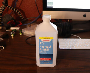
Awww yeah! Value size!

I should note that a professional would use reagent grade 99+% isopropanol, which can be purchased by the gallon from Amazon. Like I said, though, I'm not a professional, so I got mine from a drug store. The other 9% is water, which is not damaging, as long as it dries off before the card gets powered up.

Anyway, what we're going to do here is the same test, but we'll use the alcohol as a bellweather for the temperature of the SMD components on the board. Components that get REALLY hot will cause it to boil, producing very visible bubbles, but even components that get a little bit warm will cause it to evaporate off of them faster than the ones around them, which is visible to a keen eye.

So, we apply the alcohol to the board, like so:
IMG_4609.jpg

Next, we supply the circuit's operating voltage to it, and look for vapor, bubbles, fire, or components that dry off faster than the surrounding ones.

Can you see which component it is here? In case I didn't mention it before, all the pictures in this thread are of the click-to-enlarge variety.
IMG_4611.jpg
 
Back
Top