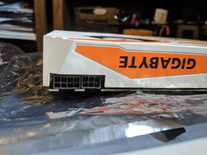
Gigabyte GTX 1080Ti Turbo Missing Capacitor

NULLOPT

n00b
Joined
May 13, 2020
Messages
7
Hello all,

I picked up a non-functioning 1080Ti, no longer under warranty. The card has no display, the leds next to the power connectors flash briefly when first booted then go dark immediately.

I noticed that there is a tiny cap that is loose (only connected to one pad) with the larger one next to it missing. I know there are a lot of unpopulated pads on this board, but bare copper is visible on those pads as if something got torn off. This card has no backplate so I guess that is why they put them there. This section of the board is right next to the power input, seems reasonable that the card would shut off if something was wrong here.

I guess what I am wondering is if anyone has an idea what the value of this capacitor might be? (ballpark estimate)

Thanks,

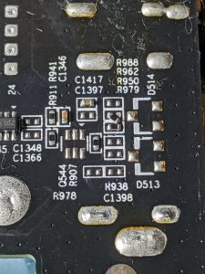
The components shown here C1859 is missing, and C513 is messed up. Next to D506 which appears to be a BAT54C Dual Schottky Barrier Diode. Looks like C1859 has a trace going to Q506.
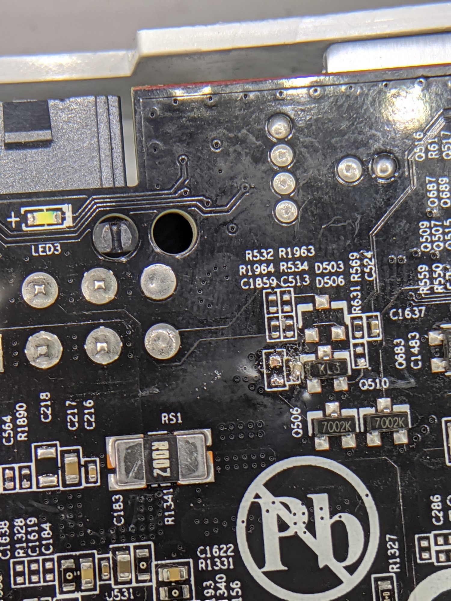
IMG_20200512_195322.jpg
 
That's probably not bare copper, but rather part of the MLC cap that was there. Be sure to clean the pads real good before you attempt to install a replacement.

What size is it? 0805?

Edit: Is this a reference board?
 
Good call on cleaning the pads.

Can't find my calipers but comparing it to the SOT23 next to it, I am thinking either 0603 or 0805

Not a reference board. It's the gigabyte 1080ti "turbo", which is apparently the same layout as their "gaming oc" but not the "aorus extreme"

Edit: Thanks for the response by the way
 
Last edited:
Good call on cleaning the pads.

Can't find my calipers but comparing it to the SOT23 next to it, I am thinking either 0603 or 0805

Not a reference board. It's the gigabyte 1080ti "turbo", which is apparently the same layout as their "gaming oc" but not the "aorus extreme"

Edit: Thanks for the response by the way
10uF is a pretty common size for 0805. Wouldn't surprise me if that's close enough, but I'm just guessing. To know for sure, you'd need either a board schematic, or a working card in hand to remove the cap from and measure. Don't forget to check the 0402 next to it for damage, too. They're real easy to damage, and when they get damaged, they often become a short.

Have you tried to figure out what that circuit is for? That SOT23 appears to be a diode, so it wouldn't surprise me if this is something like a 12V power good kind of signal, with the diode acting as flyback protection for when the the system powers down. Again, though, that's just a guess. It could also be related to the cooling fan, or something.
 
Yeah, the 0402 has some damage. I probed the pads and they are run in parallel. Don't have any 10uF SMD caps on hand, only relatively large through hole, will have to order some.

Haven't been able to find a schematic anywhere, and only have found more detailed board info about different models of 1080ti

Pretty sure you're right about it being related to the power circuit.
The fan control circuitry and headers are near the bottom edge, and the fan seems to work just fine.
 
Also found a resistor that was a little messed up right next to the HDMI output. Soldered it back in place, didn't fix card though.

IMG_20200513_211558.jpg
 
What are your resistance measurements on each of the DC rails?

Do you have the proper voltage on each one?
 
Wow, looks like someone beat the heck out of that poor card. Looks like a crazy amount of damage there, see some cracked memory chips and a lot of melted and cooked stuff.
 
Wow, looks like someone beat the heck out of that poor card. Looks like a crazy amount of damage there, see some cracked memory chips and a lot of melted and cooked stuff.
That just looks like the residue from the TIM pads, to me. Which memory chip is cracked?
 
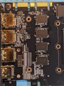
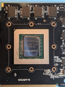
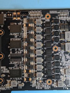
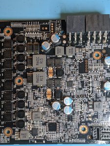
That bottom one in the first pic has a chunk out of it on the left hand side. the second pic has some damage on the left hand side on the leftmost chip. The third pic looks like it has some damage on the 2nd chip on the bottom left hand side.
 
That bottom one in the first pic has a chunk out of it on the left hand side. the second pic has some damage on the left hand side on the leftmost chip. The third pic looks like it has some damage on the 2nd chip on the bottom left hand side.
Nah, that's just residue from the TIM pads. I have a pile of dead graphics cards on my workbench, and every single one of them looks like that.
 
Resistances (In reference to ground)

8 Pin + 6 Pin

???0.8 M OhmN/A???
0.3 Ohm0.8 M Ohm0.3 Ohm0.3 OhmN/A0.3 Ohm0.8 M Ohm0.3 Ohm

The gnd and sense pins all seem good, but I am unable to get a stable reading on the 12v pins. I can measure 0v on the pins to ground, but once I switch to resistance check, the meter must start to charge some components and the resistance reading fluctuates, switching back to DCV mode will then show a voltage present that slowly dissipates. Not sure why, it's a good fluke meter, and doing the same test on a 960 that I have gives a stable ~2.4K Ohm on all the 12v pins.

With the system powered on, I get stable voltage readings in reference to ground
12.1412.1412.14-0.012N/A12.1412.1412.14
0.00-0.0120.000.00N/A0.00-0.0120.00
The sense pins show a small difference which seems normal.


IMG_20200514_154350.jpg
This is the orientation measured ^

----

Yeah, the zoomed in pictures definitely look weird, must be the lighing, all of the components on the front side seem just fine (physically)

----

Yes, I have access to hot air.
 
Resistances (In reference to ground)

8 Pin + 6 Pin

???0.8 M OhmN/A???
0.3 Ohm0.8 M Ohm0.3 Ohm0.3 OhmN/A0.3 Ohm0.8 M Ohm0.3 Ohm

The gnd and sense pins all seem good, but I am unable to get a stable reading on the 12v pins. I can measure 0v on the pins to ground, but once I switch to resistance check, the meter must start to charge some components and the resistance reading fluctuates, switching back to DCV mode will then show a voltage present that slowly dissipates. Not sure why, it's a good fluke meter, and doing the same test on a 960 that I have gives a stable ~2.4K Ohm on all the 12v pins.

With the system powered on, I get stable voltage readings in reference to ground
12.1412.1412.14-0.012N/A12.1412.1412.14
0.00-0.0120.000.00N/A0.00-0.0120.00
The sense pins show a small difference which seems normal.


View attachment 245505
This is the orientation measured ^

----

Yeah, the zoomed in pictures definitely look weird, must be the lighing, all of the components on the front side seem just fine (physically)

----

Yes, I have access to hot air.
That all sounds normal.

Next, you need to check the voltage readings on the lower voltage rails that are created by the card's circuits. Once you find them, power the system down and measure resistance to ground at each one.

You should have at least four:

1. Core voltage - should be around 1 volt. Easiest place to measure this is at the terminal of one of the chokes nearest to the GPU. Any one of the big row of chokes to the right of the GPU should work. Resistance should be low single digits. Maybe 1.5 ohms?
2. Memory voltage - should be 1.35 volts, IIRC. Similar to the core voltage - the easiest place to measure this is likely to be the terminal on the chokes that connects to the memory itself. The two big meaty chokes to the right of the core VRM are probably the ones in question. I'd guess the side you need is the space in between them. Resistance should be something like 50 ohms.
3. 1.8V - this is a secondary voltage required for G5X memory. Probe all the little chokes on the card until you find it. I don't remember what the reistance on this one is. I would assume, for the moment, that anything non-zero is OK.
4. VPLL - should be .95-1V I'm not sure what this actually does, but it's required. The card won't run without it. Resistance should be 200-500 ohms, IIRC

You should also have 3.3V somewhere, and possibly also 5V or 7V.
 
I'll check out the secondaries a bit later when I get some more time. I did a bit of tracing and it looks like the damaged circuit is hooked right up to the sense pin of the 6 pin power connector. Going to explore that a bit further. Tested the diodes and they are functioning correctly, also adding a bit of capacitance by putting my finger on that part of the board seems to keep the LED on for longer.
 
Back
Top