GotNoRice
[H]F Junkie
- Joined
- Jul 11, 2001
- Messages
- 12,006
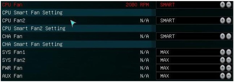
The EVGA X99 FTW has 7 fan headers. That includes three 4-Pin PWM headers on the top of the board. From left to right, they are PWR_FAN, CPU_FAN, and CPU2_FAN. All the rest, on the lower part of the board, are 3-Pin headers (CHA_FAN, AUX_FAN, SYS1_FAN, SYS2_FAN).
I knew that the motherboard only allowed three fans to be smart controlled. I assumed that it would be the three 4-pin fan ports.
When I got in the bios to configure the fans, I noticed that it showed the third smart controlled fan as "CHA Fan", presumably refering to the 3-pin "CHA_FAN" header on the bottom of the motherboard.
I made a thread on the EVGA forums asking for clarification, and an EVGA tech responded to say that it was the three 4-pin headers up top (PWR_FAN, CPU_FAN, and CPU2_FAN) that were smart controlled, even going as far as to provide a picture where he circled each of those 4-pin headers up top in red. The EVGA tech further responded by saying that the PWR_FAN header is a chassis fan, and that is why it is labeled as CHA Fan in the bios...
I decided to do my own testing by simply setting each fan to OFF in the bios, one by one, and seeing which fan actually stopped spinning on the next boot. Sure enough, the bios labeling is correct and it is the 3-Pin CHA_FAN on the bottom that is smart controlled. The 4-Pin port up top labeled PWR_Fan can't be smart controlled other than to set a manual percentage in the bios. It is a bit odd that the EVGA tech provided an answer that was 100% wrong.
I also noticed that the CPU Fan2 only lists "DC Mode" even though it too is a 4-pin fan header:
CPU Fan:
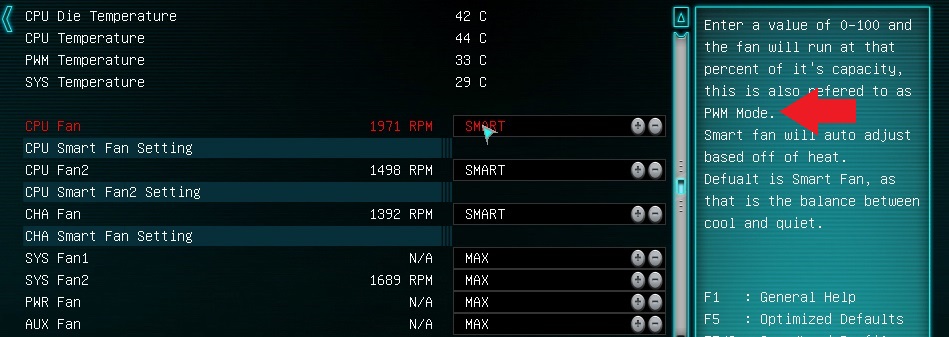
CPU Fan2:
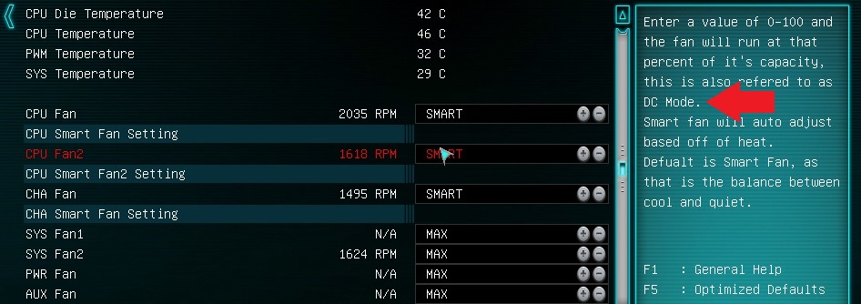
CHA Fan:
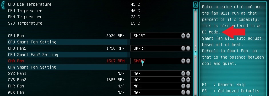
I would expect that the CHA Fan would use DC Mode, since I know now that it is a 3-pin connector. I really don't know why CPU Fan2 would be using DC Mode also, since that is a 4-pin connector. It would seem that out of the three 4-pin headers on this board, only ONE actually uses PWM, and only two out of the three can be smart controlled at all. CPU Fan2 not using PWM like the main fan might help to explain why they are always 300-500RPM apart from each other, even though they were always <100RPM apart from each other with my old motherboard. I could try maybe using a splitter and having them both run from the main CPU_FAN header, but each fan is 0.53amps which would really be pushing the 1amp limit of each header
This is the first EVGA motherboard I've ever used. Are these kinds of odd quirks normal?
I knew that the motherboard only allowed three fans to be smart controlled. I assumed that it would be the three 4-pin fan ports.
When I got in the bios to configure the fans, I noticed that it showed the third smart controlled fan as "CHA Fan", presumably refering to the 3-pin "CHA_FAN" header on the bottom of the motherboard.
I made a thread on the EVGA forums asking for clarification, and an EVGA tech responded to say that it was the three 4-pin headers up top (PWR_FAN, CPU_FAN, and CPU2_FAN) that were smart controlled, even going as far as to provide a picture where he circled each of those 4-pin headers up top in red. The EVGA tech further responded by saying that the PWR_FAN header is a chassis fan, and that is why it is labeled as CHA Fan in the bios...
I decided to do my own testing by simply setting each fan to OFF in the bios, one by one, and seeing which fan actually stopped spinning on the next boot. Sure enough, the bios labeling is correct and it is the 3-Pin CHA_FAN on the bottom that is smart controlled. The 4-Pin port up top labeled PWR_Fan can't be smart controlled other than to set a manual percentage in the bios. It is a bit odd that the EVGA tech provided an answer that was 100% wrong.
I also noticed that the CPU Fan2 only lists "DC Mode" even though it too is a 4-pin fan header:
CPU Fan:
CPU Fan2:
CHA Fan:
I would expect that the CHA Fan would use DC Mode, since I know now that it is a 3-pin connector. I really don't know why CPU Fan2 would be using DC Mode also, since that is a 4-pin connector. It would seem that out of the three 4-pin headers on this board, only ONE actually uses PWM, and only two out of the three can be smart controlled at all. CPU Fan2 not using PWM like the main fan might help to explain why they are always 300-500RPM apart from each other, even though they were always <100RPM apart from each other with my old motherboard. I could try maybe using a splitter and having them both run from the main CPU_FAN header, but each fan is 0.53amps which would really be pushing the 1amp limit of each header
This is the first EVGA motherboard I've ever used. Are these kinds of odd quirks normal?