Don;t Shunt Mod!

Yeah it's very weird... i watched this yesterday.. the title says do not shunt mod... the damage definitely looks like it is from liquid metal eating away at the solder and that is nvidias fault?
 
yah, shunt modding seems to have weakened the solder joints
 
It has been a long time since I did a voltage mod but why go through the trouble with the liquid metal? Wouldn't a blob of solder be alot less hasle?
 
Sure, this is Nvidia's fault for locking their cards to 120% power in the bios..
/75%sarcasm

It has been a long time since I did a voltage mod but why go through the trouble with the liquid metal? Wouldn't a blob of solder be alot less hasle?
I think a dab of solder has too low resistance compared to the liquid metal and the card realizes something is up.
 
It has been a long time since I did a voltage mod but why go through the trouble with the liquid metal? Wouldn't a blob of solder be alot less hasle?

The solder would be a more permanent fix. It could be removed with a copper braid or something similar, but with the heat directed on top of the resistor to remove it may damage the part. It's much easier to just wipe away the paste.
 
Isn't this what conductive pens (markers) are for? I know that back in the Athlon XP days, this stuff was suggested, or to "pencil mod" it (I doubt the graphite would conduct enough in this instance). That's what I used to mod my XPs into MPs :)

Which for the non-automotive people here, that's to repair the little lines in your vehicle's back window, the "rear window defroster". What they do is not dissimilar from your toaster, as one end is connected to Positive power, the other end to Negative (grounded), and all it effective does is create a "short circuit", but since it's a very long and resistive short, it gets very hot; thus, melting the ice. However, these lines CAN get damaged, causing there to be no connection, and this 'paint' is just laden with copper flake so that you can re-connect the lines. I would say it'd work great for this sort of modding, given it A) has to carry enough power in a car's system (~14.4V DC), B) gets fairly hot and has to withstand that temperature as well.

After doing some digging, though, it seems likely to be the silver in the solder to blame. However, I wasn't able to come up with the 'electrode potential' of typical solder, which is Tin-Lead-Silver. I dunno what the industry generally uses, nevermind what ratios, since consumer stuff is usually only like 2% to 4% Silver. Either way, Gallium (Ga) looks to be -0.53V, and straight Silver (Ag) is +0.7996V, but Tin (Sn) and Lead (Pb) being -0.13V and -0.126V respectively. Therefore, as a Tin-Lead-Silver alloy, I'd suspect it'd still be around the -0.1V, which would be enough to kick start the galvanic reaction (aka, make a battery).

Either way, this was a really interesting read:
http://forum.notebookreview.com/thr...-compatibility-with-copper-heat-sinks.800890/
I pulled the rest from:
https://en.wikipedia.org/wiki/Standard_electrode_potential_(data_page)
 
As an Amazon Associate, HardForum may earn from qualifying purchases.
It's also the wrong way to shunt a card! :eek:

Here's the proper way:
https://xdevs.com/guide/pascal_oc/
Note that earlier version of this guide incorrectly mentioned need to short RS1, RS2, RS3. This is wrong, and will cause card clock to lock at 135MHz. Do not short shunt resistors themselves, but add resistors like shown on photo below. Sorry for confusion.
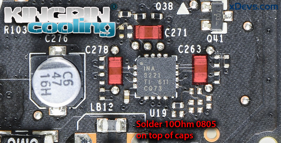

pwrmod.jpg


...and a real-world example here: :D

https://hardforum.com/threads/nvidia-announces-the-new-titan-x.1905829/page-33#post-1042511061
 
Back
Top