Converting 240v to 120v lighting

Joined
May 9, 2021
Messages
13
Hello, new to the forum, hoping I can get some help.

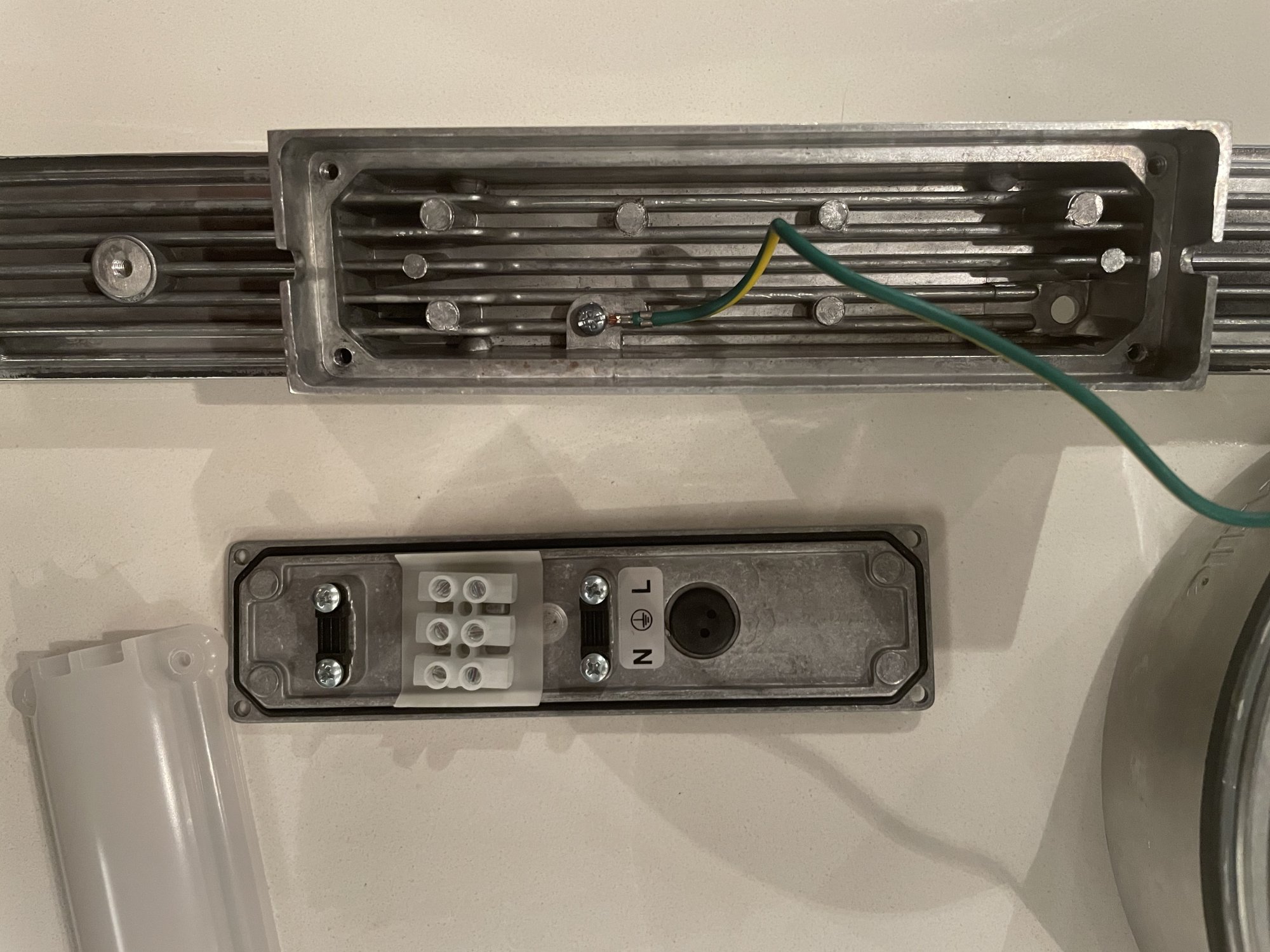
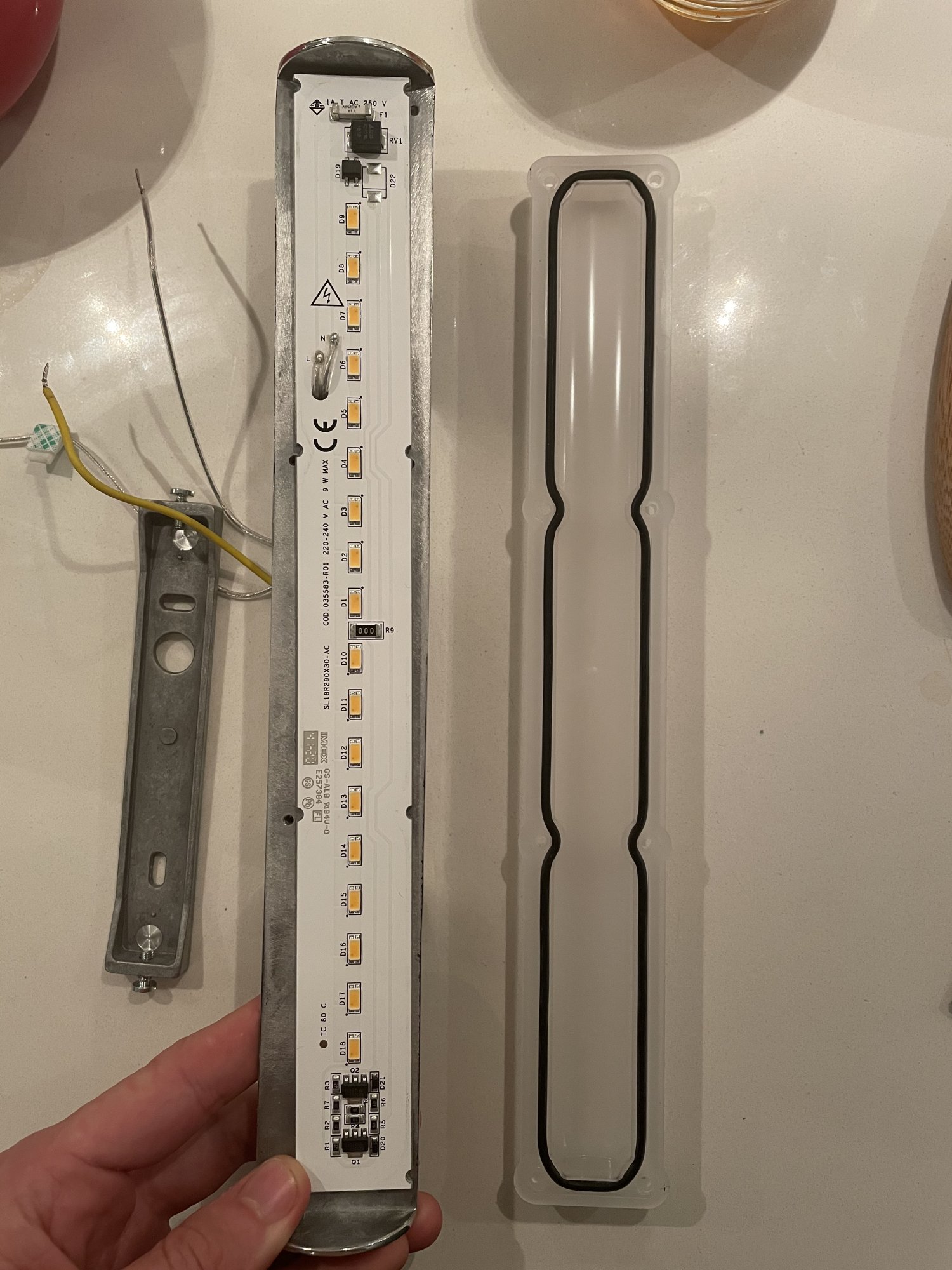
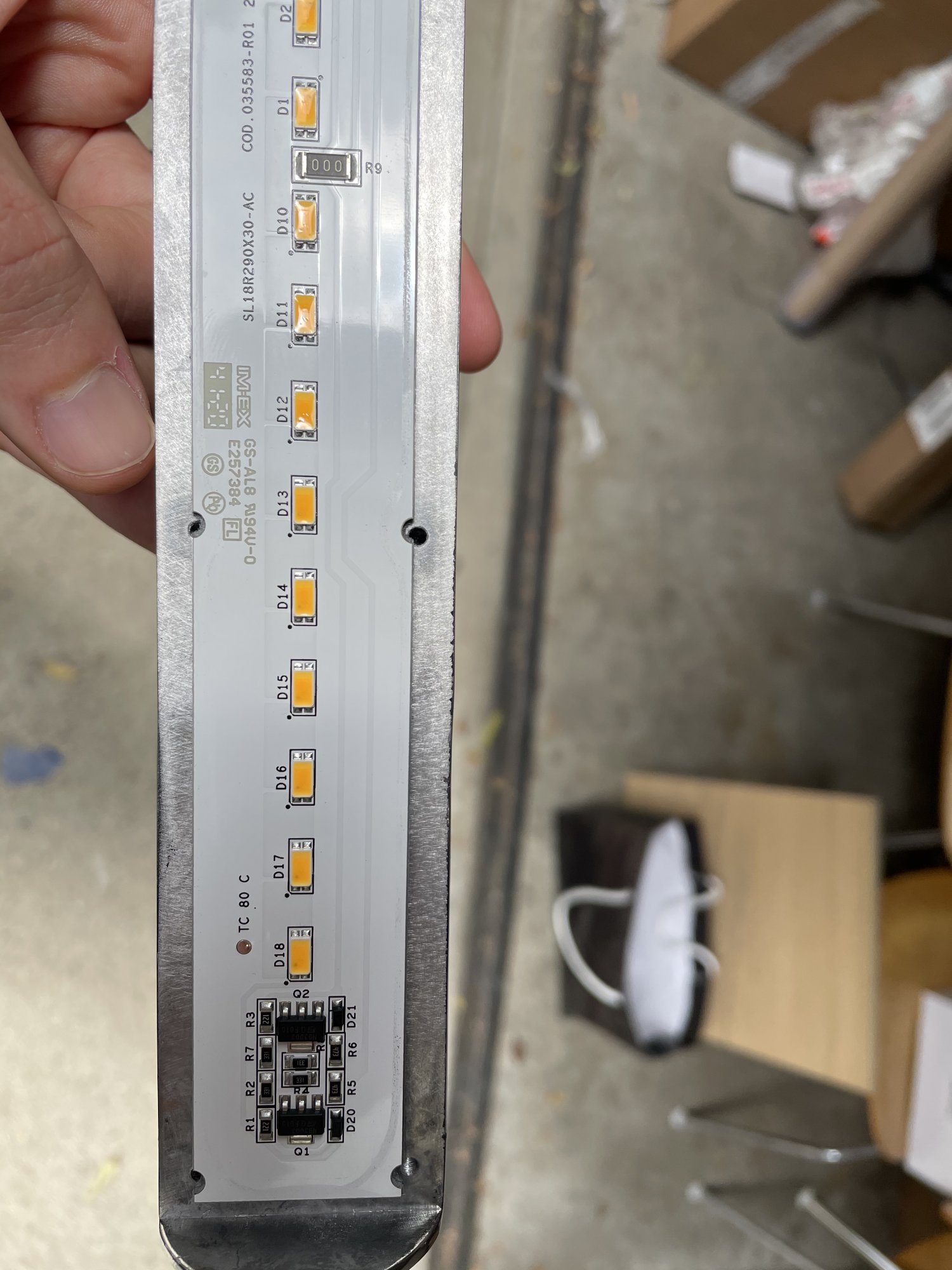
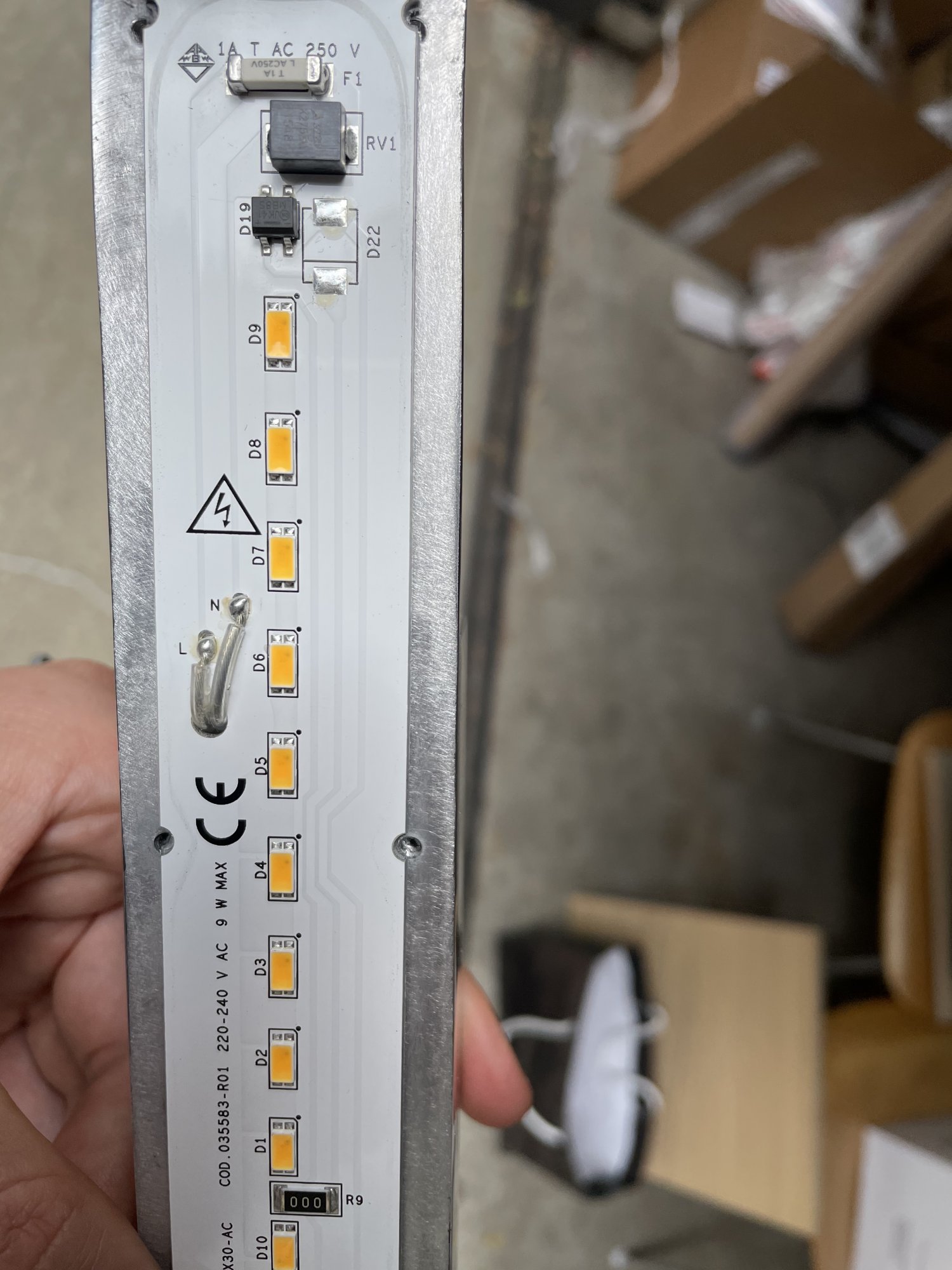
I bought a 220-240v led light that I need converting to 120v.

I can’t get a 120v version as they don’t make them for the US market, hope I can do some DIY alterations to make them work.

Pardon my lack of wordage around this stuff, the main line is connected to a TDK varistor 3225 K275; is this what’s regulating the power to the LED panel? Can I just replace this with the appropriate resistor to be compatible with 120v input?

I’ve attached some images, maybe they can help!
 

Attachments

  • 9F7F2538-4DE9-49FA-9830-2BC25943EA9E.jpeg
    9F7F2538-4DE9-49FA-9830-2BC25943EA9E.jpeg
    305.3 KB · Views: 0
  • B0A1B88C-C2F9-4EDC-89A4-858A7630336B.jpeg
    B0A1B88C-C2F9-4EDC-89A4-858A7630336B.jpeg
    306.8 KB · Views: 0
They make transformers you can buy on ebay to go from 120v and 220v. Also, LEDs take so little power you probably don't even need a crazy beefy one. I bet your light will never exceed 30w depending on length.
 
They make transformers you can buy on ebay to go from 120v and 220v. Also, LEDs take so little power you probably don't even need a crazy beefy one. I bet your light will never exceed 30w depending on length.
Hey thanks for replying. This lamp is rated at 8.3w and the PCB says 9w max.

The problem is that it was made for 220 and if I just put it on 120v mains, I suspect it will be very dim or not turn on at all, as the resistors and other components were installed to mitigate 220v down to the appropriate operating voltage.

I want to try and replace some components to make this lamp function properly on a 120v input.
The lamp has 18 leds, and the rating is 8.3w, so that’s .46w per led. Need to find out what parts to install to allow the lamp to function at that wattage.
I wouldn't bother modifiying the unit itself. Can you post of pic of what the plug looks like?
 
I wouldn't bother modifiying the unit itself. Can you post of pic of what the plug looks like?
I can a little later, but essentially it is a j box connection with a mounting plate and the the lamp. It’s a hard wire install. Probably no room for a step up transformer, I.e. from 120 (line voltage) to 240 (lamp)
 
Last edited:
Yea that probably wouldn’t fit even if it took it apart and used the parts inside the j box. I’m pretty keen on figuring out how all this works on a circuit board, could be a very good and overdue lesson on circuits and electricity in general. I studied philosophy in college :p
 
As an eBay Associate, HardForum may earn from qualifying purchases.
Yea that probably wouldn’t fit even if it took it apart and used the parts inside the j box. I’m pretty keen on figuring out how all this works on a circuit board, could be a very good and overdue lesson on circuits and electricity in general. I studied philosophy in college :p

If you have no electrical engineering knowledge, I would highly discourage you from tackling this. Soldering components on a PCB is not easy and is very easy to damage.

The easier option would be to get another junction box and stuff a 120v - 240v transformer inside it.
 
  • Like
Reactions: travm
like this
Yea that probably wouldn’t fit even if it took it apart and used the parts inside the j box. I’m pretty keen on figuring out how all this works on a circuit board, could be a very good and overdue lesson on circuits and electricity in general. I studied philosophy in college :p
attach a plug to the cord leads, plug in the box. plug the box into our normal outlets. I think you're overthinking this.
 
  • Like
Reactions: travm
like this
If you have no electrical engineering knowledge, I would highly discourage you from tackling this. Soldering components on a PCB is not easy and is very easy to damage.

The easier option would be to get another junction box and stuff a 120v - 240v transformer inside it.
I appreciate the word of caution.

I’ve soldered things before, not like this but I’m willing to accept the challenge.

I’m really looking for someone to help me understand how this circuit is working, so I know what’s what and what to replace and with what specifications.

I’ve been watching countless you tube videos trying to learn. Whether I get this thing working properly or not, I’m in. Need to get to the bottom of it! :D
 
Been sussing out the general layout of the circuit from the photos and it appears to me to be using active current regulation by way of the Q1/Q2 components (which look to be either transistor packages or dedicated current regulation chips). In theory, replacing some of those tiny resistors associated with them would "reprogram" the current regulation but without reconstructing the whole circuit diagram in full detail and doing all the math (which I'm too tired for at the moment) I can't say what values you would need or even if it would be sure to work. I'll take a look later if I'm up for it and see if I can't glean more detail with the meagre knowledge/skill I have but I'm not sure I'll be able to get exact component values with my knowledge and energy levels. One thing I can say for sure is that the varistor is not regulating the current; it's there to absorb big voltage spikes from the mains that might damage the LED chips- note how one side is connected directly to Neutral and the other is connected directly to Live (via the fuse)- when a large enough spike comes along its resistance drops enormously and effectively shorts Live to Neutral which causes the varistor to absorb the spike saving the rest of the circuit.

Since you're on a YouTube bender, I highly recommend checking out BigCliveDotCom if you haven't already. He has a a plethora of videos about modding mains-powered LED lights and goes into a lot of depth with reverse engineering boards he gets and explaining why it's put together the way it is, what each component does, and how to go about calculating values for modifying for different current/voltage.
 
Is this light an AliExpress chineseium special? Because it ticks all of the marks of being a crap dangerous fire hazard. It honestly needs to be thrown in the trash. The first problem with it is the mains wires going through the heatsink and doing a 90 degree turn across the sharp metal and PCB. It's shitty aluminum core wire with some horrific looking insulation you'd find on cheap christmas lights at dollar tree. That insulation is going to cook and crack apart, eventually exposing the mains directly to the aluminum heatsink and make the whole light live at mains voltage at minimum, or cause a fire at worst. Since that part is not fused and doesn't even appear to be grounded, the mains will just think its a heavy load and burn your house down.

The second problem is that if that's how the light came to you, it's an electrocution hazard. There's no galvanic isolation between the mains and the LEDs, making the whole circuit board a death trap. You have high voltage rectified mains on the surface of the PCB just waiting to kill someone.

And the third is that the PCB has virtually zero isolation for the high voltage DC. There's a zero ohm link slapped right on top of the ground return line for the LEDs, with the only thing between being the microns thick conformal coating on the trace.

Don't bother trying to get this light working, it's a death trap, toss it in the trash where it belongs. If you need an LED work light, go down to Walmart and buy one, they're cheap enough. I saw one on sale last week for $40 and you can be assured it's not going to be a death trap, and properly designed to work on 120v mains. If that's too expensive for you, then get one of the long low voltage DC strips instead. You can get 4 foot long 12v DC LED lights for cheap on AliExpress, Ebay, Banggood, etc. and you don't have to worry about killing yourself or burning your house down.

Been sussing out the general layout of the circuit from the photos and it appears to me to be using active current regulation by way of the Q1/Q2 components (which look to be either transistor packages or dedicated current regulation chips). In theory, replacing some of those tiny resistors associated with them would "reprogram" the current regulation but without reconstructing the whole circuit diagram in full detail and doing all the math (which I'm too tired for at the moment) I can't say what values you would need or even if it would be sure to work.

It's not possible to convert this light to 120v operation, changing the current to the LEDs won't change that. When laying out a LED light module to operate directly on AC mains, you have to decide what voltage you want to run it on, because you need so many LEDs to make up the mains RMS voltage. In this LED module, it has two strings of 9 LED packages, with I'm guessing 8 chip LED modules to make up the ~320v RMS DC coming off the bridge rectifier. If you power this LED light with 120v, you'll get an RMS about 170v DC, which is only about half the voltage you need to run the light. No amount of component shuffling on the linear regulation is going to make this light work because of the lack of voltage.

To get this light to work on 120v, you'd have to carve up traces and rewire the entire circuit, not really something you want to do on something operating at mains voltage. Or you'd have to use a voltage doubler. But this light is so dangerous that it just needs to be thrown away.
 
Is this light an AliExpress chineseium special? Because it ticks all of the marks of being a crap dangerous fire hazard. It honestly needs to be thrown in the trash. The first problem with it is the mains wires going through the heatsink and doing a 90 degree turn across the sharp metal and PCB. It's shitty aluminum core wire with some horrific looking insulation you'd find on cheap christmas lights at dollar tree. That insulation is going to cook and crack apart, eventually exposing the mains directly to the aluminum heatsink and make the whole light live at mains voltage at minimum, or cause a fire at worst. Since that part is not fused and doesn't even appear to be grounded, the mains will just think its a heavy load and burn your house down.

The second problem is that if that's how the light came to you, it's an electrocution hazard. There's no galvanic isolation between the mains and the LEDs, making the whole circuit board a death trap. You have high voltage rectified mains on the surface of the PCB just waiting to kill someone.

And the third is that the PCB has virtually zero isolation for the high voltage DC. There's a zero ohm link slapped right on top of the ground return line for the LEDs, with the only thing between being the microns thick conformal coating on the trace.

Don't bother trying to get this light working, it's a death trap, toss it in the trash where it belongs. If you need an LED work light, go down to Walmart and buy one, they're cheap enough. I saw one on sale last week for $40 and you can be assured it's not going to be a death trap, and properly designed to work on 120v mains. If that's too expensive for you, then get one of the long low voltage DC strips instead. You can get 4 foot long 12v DC LED lights for cheap on AliExpress, Ebay, Banggood, etc. and you don't have to worry about killing yourself or burning your house down.


It's not possible to convert this light to 120v operation, changing the current to the LEDs won't change that. When laying out a LED light module to operate directly on AC mains, you have to decide what voltage you want to run it on, because you need so many LEDs to make up the mains RMS voltage. In this LED module, it has two strings of 9 LED packages, with I'm guessing 8 chip LED modules to make up the ~320v RMS DC coming off the bridge rectifier. If you power this LED light with 120v, you'll get an RMS about 170v DC, which is only about half the voltage you need to run the light. No amount of component shuffling on the linear regulation is going to make this light work because of the lack of voltage.

To get this light to work on 120v, you'd have to carve up traces and rewire the entire circuit, not really something you want to do on something operating at mains voltage. Or you'd have to use a voltage doubler. But this light is so dangerous that it just needs to be thrown away.
Hello :D

Well that’s pretty damning. I obviously can’t speak on the integrity of the PCB and the safety of the circuitry but the design of the casing for light is not a piece of crap, at least not in my opinion. The light is called Kartell Rifly wall lamp, it’s intended to be put in a bathroom. It has a large aluminum structure that the PCB sits on and then a protective plastic case with a rubber gasket fits on top of it. Then a decorative light diffusing shade goes on top of the whole things. It’s a very pretty light, that’s why I really want to make it work. It’s widely sold in Europe and for a long time was sold in US, currently not for sale in US due to a lack of UL certification, not sure what changed, maybe some of the things you mentioned became non compliant.
Throwing it out isn’t really an option. I know this may seem dumb but I work in design (obviously not circuit design), and using this light for the project at hand is something I’m not yet ready to give up on.
I’ve attached some additional photos that may help you get a better idea of what this lamp is, including a photo of the ground and how it’s attached.
I plugged the light in directly into an socket today, it lit up fine albeit a bit dim. More a mood light than an illumination light. I might be ok with using it in that capacity. Do you still maintain that this is not safe because of the circuitry? Do I have any alternatives while still keeping the casing of the whole lamp?
 
additional pictures
 

Attachments

  • 3595DB50-6B27-4687-AFF2-5AD99998AAAA.jpeg
    3595DB50-6B27-4687-AFF2-5AD99998AAAA.jpeg
    425 KB · Views: 0
  • DE3ECF79-9212-434E-9C95-0B383FC9A84E.jpeg
    DE3ECF79-9212-434E-9C95-0B383FC9A84E.jpeg
    409.9 KB · Views: 0
WOW, that thing is designed to go in a bathroom? It's no mystery why it doesn't have a UL certification with the issues it has. I see that it has a ground wire, but that doesn't excuse the rest of the horrific design problems.

The new pictures show even more design faults. They tried to make the unit water tight with rubber gaskets, but completely defeated them on the back box of the unit. It looks like it was originally designed for a much safer ballast to drive a CFL bulb with how big the box is and the multiple untapped lugs inside. There are cutout channels on the sides of the box, and a hole going into the area with the LED module. This basically allows humidity inside the light, which will condense with the natural temperature inversions in the bathroom and cause corrosion. But even the rubber gaskets are a problem, if those things are rubber. Rubber dry rots and contracts, which will allow even more humidity inside the light.

I would in no circumstance put this anywhere near a bathroom or any other place with high humidity or water. Again, the safest place would be the trash. If you must use this fixture, gut the mains voltage LED module and put in a low voltage one. Again, you can get low voltage LED strip and hide a low voltage transformer in the base where the ballast normally goes. It would make it far safer and not risk burning your house down.

You can get stuff like this:

https://www.ebay.com/itm/402641265364

And it's cuttable. If you look at the PCBs, you can see every so many LEDs there are copper pads, you can use a saw to cut between the pads to get a smaller section if need be and it will still run on the same 12/24v the strip is rated at.

For the power supply, you could hide a sealed wall wart in the space where the ballast would normally go.

https://www.ebay.com/itm/203124819853

Just chop the ends off the wires and use wire nuts for the mains side and terminal blocks for the DC side.
 
Last edited:
As an eBay Associate, HardForum may earn from qualifying purchases.
WOW, that thing is designed to go in a bathroom? It's no mystery why it doesn't have a UL certification with the issues it has. I see that it has a ground wire, but that doesn't excuse the rest of the horrific design problems.

The new pictures show even more design faults. They tried to make the unit water tight with rubber gaskets, but completely defeated them on the back box of the unit. It looks like it was originally designed for a much safer ballast to drive a CFL bulb with how big the box is and the multiple untapped lugs inside. There are cutout channels on the sides of the box, and a hole going into the area with the LED module. This basically allows humidity inside the light, which will condense with the natural temperature inversions in the bathroom and cause corrosion. But even the rubber gaskets are a problem, if those things are rubber. Rubber dry rots and contracts, which will allow even more humidity inside the light.

I would in no circumstance put this anywhere near a bathroom or any other place with high humidity or water. Again, the safest place would be the trash. If you must use this fixture, gut the mains voltage LED module and put in a low voltage one. Again, you can get low voltage LED strip and hide a low voltage transformer in the base where the ballast normally goes. It would make it far safer and not risk burning your house down.
Thanks for all of that, the fact that you’re so adamant about it’s poor design is definitely pushing me in the direction of scrapping the whole LED module. The problem is that the PCB is shaped to fit into the plastic cover and make contact with the gasket, then the whole thing gets tightened down to the aluminum housing. Maybe I can clear the PCB of all components and glue low voltage LED strip to the PCB? And also use some silicone to help seal it?

could I still make it dim well?

can you point me to some quality components I would need, i.e. quality LED strip and transformer? The original PCB is about 11 1/4” long.
 
Been sussing out the general layout of the circuit from the photos and it appears to me to be using active current regulation by way of the Q1/Q2 components (which look to be either transistor packages or dedicated current regulation chips). In theory, replacing some of those tiny resistors associated with them would "reprogram" the current regulation but without reconstructing the whole circuit diagram in full detail and doing all the math (which I'm too tired for at the moment) I can't say what values you would need or even if it would be sure to work. I'll take a look later if I'm up for it and see if I can't glean more detail with the meagre knowledge/skill I have but I'm not sure I'll be able to get exact component values with my knowledge and energy levels. One thing I can say for sure is that the varistor is not regulating the current; it's there to absorb big voltage spikes from the mains that might damage the LED chips- note how one side is connected directly to Neutral and the other is connected directly to Live (via the fuse)- when a large enough spike comes along its resistance drops enormously and effectively shorts Live to Neutral which causes the varistor to absorb the spike saving the rest of the circuit.

Since you're on a YouTube bender, I highly recommend checking out BigCliveDotCom if you haven't already. He has a a plethora of videos about modding mains-powered LED lights and goes into a lot of depth with reverse engineering boards he gets and explaining why it's put together the way it is, what each component does, and how to go about calculating values for modifying for different current/voltage.


sorry didn’t mean to ignore! Yea I discovered Clive a while ago, super engaging content, I don’t understand most of it but he’s great, just something calming about his videos.

I think on the whole, this project might be a little too advanced or maybe not even worth it to begin with. I think wiring a mew LED module to the fixture might be the move.

let’s see what gifabite says next ;)
Yeah I agree swapping the strip is an easier, safer, more sure bet.
 
Thanks for all of that, the fact that you’re so adamant about it’s poor design is definitely pushing me in the direction of scrapping the whole LED module. The problem is that the PCB is shaped to fit into the plastic cover and make contact with the gasket, then the whole thing gets tightened down to the aluminum housing. Maybe I can clear the PCB of all components and glue low voltage LED strip to the PCB? And also use some silicone to help seal it?

You can try scraping off the components, but aluminum core PCBs are really irritating to remove components from. But since you're not going to care about salvaging them, you can use a heat gun to get it hot and pull the components off. I'd recommend taking out the LED board and doing it on concrete or something so you don't have to deal with the aluminum heatsink sucking all of the heat away, and potentially damaging the finish on it.

But with the pictures you show, it doesn't look like the original LED PCB really needs to be there if the plastic decorative cover attaches to the aluminum heatsink base, unless the screws are too long.

With the lower voltage LED tape, you have to worry less about humidity. It will still be a problem, but since the new circuitry would be sealed, it's less of an issue. I wouldn't recommend using silicone caulk because it's corrosive. You can get something like dielectric grease and lightly coat the rubber to help seal it and then wipe off the excess. For the holes in the base, you could try RTV, the stuff used to make engine gaskets. It's not nearly as corrosive as normal caulk is.

could I still make it dim well?

You can make it dim, but it take some extra effort. You'd need a dimmer controller like this:

https://www.homedepot.com/p/Armacos...ver-12-Volt-DC-Power-Supply-820200/313549742?

And a more complicated dimmer light switch (I think this one will work with above dimmer):

https://www.homedepot.com/p/Lutron-...candescent-Bulbs-Gray-DVCL-153PR-GR/305582999

With the above LED driver brick, it'd be both the power supply and dimmer controller, so you wouldn't have to mickey mouse on extra parts for the dimmer to function. All you'll need to do is not use the power cord and wire it directly to the romex wiring in the junction box. It looks like it has lugs hidden under the blue plastic for such connections. If not, you can chop the power cord and use wire nuts from it to the romex in the junction box.

can you point me to some quality components I would need, i.e. quality LED strip and transformer? The original PCB is about 11 1/4” long.

The above are quality parts. As for the rigid LED strips, I've really not had any problems with the chineseium stuff as long as you properly cool it with thermal paste and a heatsink. You'll pay a lot less for it than the overpriced stuff at the hardware store. You can get the stuff that matters for safety like the power supply and switch at the hardware store, and the stuff that doesn't, the LED strips from eBay or elsewhere.

Since 11 and a quarter inches isn't a standard length, you'll probably just have to buy a longer section and cut it down. There are plenty of foot long rigid LED strips online:

6000k cool white:
https://www.amazon.com/dp/B07QWJLZGY

3000k warm white:
https://www.amazon.com/dp/B07QXHLZY6/
 
As an Amazon Associate, HardForum may earn from qualifying purchases.
Is this the light fixture? https://www.kartell.com/NO/all/rifly/09340
I'm surprised this light goes for over $500 USD after reading GiGaBiTe criticize it.
That’s it. It’s “Italian made”, I’m baffled as to why they would use such a poorly designed LED module. Having said that, I used to work for this company’s showroom and we had a pendant version of this light, it was turned on 24/7 for several years and I never saw it burn out, so maybe the diagnosis is a little harsh.

regardless since I need it at 120v the retrofit of the LED strip in to the casing seems like a sensible work around.
 
You can try scraping off the components, but aluminum core PCBs are really irritating to remove components from. But since you're not going to care about salvaging them, you can use a heat gun to get it hot and pull the components off. I'd recommend taking out the LED board and doing it on concrete or something so you don't have to deal with the aluminum heatsink sucking all of the heat away, and potentially damaging the finish on it.

But with the pictures you show, it doesn't look like the original LED PCB really needs to be there if the plastic decorative cover attaches to the aluminum heatsink base, unless the screws are too long.

With the lower voltage LED tape, you have to worry less about humidity. It will still be a problem, but since the new circuitry would be sealed, it's less of an issue. I wouldn't recommend using silicone caulk because it's corrosive. You can get something like dielectric grease and lightly coat the rubber to help seal it and then wipe off the excess. For the holes in the base, you could try RTV, the stuff used to make engine gaskets. It's not nearly as corrosive as normal caulk is.


You can make it dim, but it take some extra effort. You'd need a dimmer controller like this:

https://www.homedepot.com/p/Armacos...ver-12-Volt-DC-Power-Supply-820200/313549742?

And a more complicated dimmer light switch (I think this one will work with above dimmer):

https://www.homedepot.com/p/Lutron-...candescent-Bulbs-Gray-DVCL-153PR-GR/305582999

With the above LED driver brick, it'd be both the power supply and dimmer controller, so you wouldn't have to mickey mouse on extra parts for the dimmer to function. All you'll need to do is not use the power cord and wire it directly to the romex wiring in the junction box. It looks like it has lugs hidden under the blue plastic for such connections. If not, you can chop the power cord and use wire nuts from it to the romex in the junction box.


The above are quality parts. As for the rigid LED strips, I've really not had any problems with the chineseium stuff as long as you properly cool it with thermal paste and a heatsink. You'll pay a lot less for it than the overpriced stuff at the hardware store. You can get the stuff that matters for safety like the power supply and switch at the hardware store, and the stuff that doesn't, the LED strips from eBay or elsewhere.

Since 11 and a quarter inches isn't a standard length, you'll probably just have to buy a longer section and cut it down. There are plenty of foot long rigid LED strips online:

6000k cool white:
https://www.amazon.com/dp/B07QWJLZGY

3000k warm white:
https://www.amazon.com/dp/B07QXHLZY6/

cool, thank you.

The rubber gasket is slightly recessed into the the underside of the cover, so if I scrap it and screw the cover on to the aluminum housing, the plastic will make contact but the gasket won’t seal; so I think I have to scrape the PCB off and put new LED strip onto the remaking aluminum.
You can try scraping off the components, but aluminum core PCBs are really irritating to remove components from. But since you're not going to care about salvaging them, you can use a heat gun to get it hot and pull the components off. I'd recommend taking out the LED board and doing it on concrete or something so you don't have to deal with the aluminum heatsink sucking all of the heat away, and potentially damaging the finish on it.

But with the pictures you show, it doesn't look like the original LED PCB really needs to be there if the plastic decorative cover attaches to the aluminum heatsink base, unless the screws are too long.

With the lower voltage LED tape, you have to worry less about humidity. It will still be a problem, but since the new circuitry would be sealed, it's less of an issue. I wouldn't recommend using silicone caulk because it's corrosive. You can get something like dielectric grease and lightly coat the rubber to help seal it and then wipe off the excess. For the holes in the base, you could try RTV, the stuff used to make engine gaskets. It's not nearly as corrosive as normal caulk is.


You can make it dim, but it take some extra effort. You'd need a dimmer controller like this:

https://www.homedepot.com/p/Armacos...ver-12-Volt-DC-Power-Supply-820200/313549742?

And a more complicated dimmer light switch (I think this one will work with above dimmer):

https://www.homedepot.com/p/Lutron-...candescent-Bulbs-Gray-DVCL-153PR-GR/305582999

With the above LED driver brick, it'd be both the power supply and dimmer controller, so you wouldn't have to mickey mouse on extra parts for the dimmer to function. All you'll need to do is not use the power cord and wire it directly to the romex wiring in the junction box. It looks like it has lugs hidden under the blue plastic for such connections. If not, you can chop the power cord and use wire nuts from it to the romex in the junction box.


The above are quality parts. As for the rigid LED strips, I've really not had any problems with the chineseium stuff as long as you properly cool it with thermal paste and a heatsink. You'll pay a lot less for it than the overpriced stuff at the hardware store. You can get the stuff that matters for safety like the power supply and switch at the hardware store, and the stuff that doesn't, the LED strips from eBay or elsewhere.

Since 11 and a quarter inches isn't a standard length, you'll probably just have to buy a longer section and cut it down. There are plenty of foot long rigid LED strips online:

6000k cool white:
https://www.amazon.com/dp/B07QWJLZGY

3000k warm white:
https://www.amazon.com/dp/B07QXHLZY6/

Hey thank you again, all of this is super helpful.

The aluminum PCB fits into the recessed part of the plastic cover, where it makes contact with the gasket. So if I get rid of it and tighten down the plastic cover to the aluminum housing, the plastic will make contact but the gasket won’t seal; I think I have to remove the components and reuse the aluminum PCB. I think if I remove most of the solder it will be relatively flat for new strip application.

questions about components. I did some eBay searching and the company that came up that looks high end (this fixture wasn’t cheap so I want to do it justice), is called Diode LED, they have a product called Blaze X WET location LED tape light:

https://www.diodeled.com/blaze-x-wet-location-led-tape-light.html

the way I spec’d it is 12v 2700k 300+ lumen 16.4 foot spool

it looks like you can cut it every inch, with 3 LED’s per inch. So if I do 8 inches, that’s 24 LED’s ; does that make sense, will it be bright enough? I should also mention that I was planning on putting 2 of these fixture side by side, operating both on 1 J box and 1 switch. 2 identical cylindrical sconces would look really cool.

so that will be a total of 48 LED’s as the main lighting for the bathroom.

the original PCB spec is rated at 8.3w at 2700K, if feel like that’s intended to give off a lot more light than this retro fit, am I thinking about it the right way?

here are the link to the products:
https://www.diodeled.com/blaze-x-wet-location-led-tape-light.html

https://www.diodeled.com/custom/download/productFile/filename/DI-WBLX-Specification Sheet.pdf/

the switch will be a 2 gang switch, one for bathroom vent, 1 for the 2 wall sconces. Probably the same Lutron switch you sent previously. Now just have to figure out the power supply/dimming.

the housing with the untapped lugs that you described, probably doesn’t have enough space for a driver. So I’ll probably have to put in the box that’s in the wall. Would something like this work:

https://www.diodeled.com/omnidrive-basics.html

Keep in mind this will be driving two sconces, for a total of 48 LED’s

I really appreciate the help!
 
Last edited:
As an Amazon Associate, HardForum may earn from qualifying purchases.
questions about components. I did some eBay searching and the company came up that looks high end (this fixture wasn’t cheap so I want to do it justice), they’re called Diode LED, the have a product called Blaze X WET location LED tape light:

https://www.diodeled.com/blaze-x-wet-location-led-tape-light.html

the way I spec’d it is 12v 2700k 300+ lumen 14 foot spool

it looks like you can cut it every inch, with 3 LED’s per inch. So if I do 8 inches, that’s 24 LED’s ; does that make sense, will it be bright enough?

LED tape is very bright, but you need to make sure to heatsink it to something or the LEDs will burn up. And I'd definitely not recommend that company's LED tape, they want $332 per 16 foot roll, which is beyond absurd. You can get the same 16 foot roll on Ebay for between $14-$30. The waterproof tape is the exact same as the non-waterproof tape, they just coat it with a silicone conformal coating to keep moisture out. It does make it a bit difficult to connect wires, you have to carve off some of the silicone to get to the power bus pads.

the housing with the untapped lugs that you described, probably doesn’t have enough space for a driver. So I’ll probably have to put in the box that’s in the wall. Would something like this work:

https://www.diodeled.com/omnidrive-basics.html

Keep in mind this will be driving two sconces, for a total of 48 LED’s

I really appreciate the help!

If the back plate sits too low in the housing, you could probably get some longer screws and sandwich the LED driver module in. But this is only if the box isn't deep enough, it won't help if the length and width are too small.

That stainless steel cased driver doesn't look like its rated for wet locations, so I'd be a bit wary of using it. Stuffing active electronics in the wall isn't really a great thing to do because if it fails and starts smouldering, you won't know about it until it's too late.

You shouldn't have problems driving two lights off the one ballast of either the home depot one or the one you listed. You'll just have to run a second low voltage wire to the other light. You'll want to keep the wire away from the mains if possible to prevent capacitive coupling.
 
LED tape is very bright, but you need to make sure to heatsink it to something or the LEDs will burn up. And I'd definitely not recommend that company's LED tape, they want $332 per 16 foot roll, which is beyond absurd. You can get the same 16 foot roll on Ebay for between $14-$30. The waterproof tape is the exact same as the non-waterproof tape, they just coat it with a silicone conformal coating to keep moisture out. It does make it a bit difficult to connect wires, you have to carve off some of the silicone to get to the power bus pads.


If the back plate sits too low in the housing, you could probably get some longer screws and sandwich the LED driver module in. But this is only if the box isn't deep enough, it won't help if the length and width are too small.

That stainless steel cased driver doesn't look like its rated for wet locations, so I'd be a bit wary of using it. Stuffing active electronics in the wall isn't really a great thing to do because if it fails and starts smouldering, you won't know about it until it's too late.

You shouldn't have problems driving two lights off the one ballast of either the home depot one or the one you listed. You'll just have to run a second low voltage wire to the other light. You'll want to keep the wire away from the mains if possible to prevent capacitive coupling.

Ok! I don’t think I can fit a driver into the housing, not nearly enough room as the back plate drops in pretty deep. So I guess I have to put in the j box, a little scary , any way to make it safer?

im not sure what you mean by heat sinking the LED’s, I know that the aluminum PCB acts like a heat sink, so are you saying that I just need to make sure that the LED tape is adhered directly to the aluminum?
 
Ok! I don’t think I can fit a driver into the housing, not nearly enough room as the back plate drops in pretty deep. So I guess I have to put in the j box, a little scary , any way to make it safer?

If it's inside the junction box, it's a bit less scary than shoving it into the insulation or empty space in the wall. But if you can get some really long screws to replace the short ones for the back of the housing, you could just use the LED driver as a spacer and screw the back plate in gingerly. That whole light doesn't look very heavy, I don't think it'd be a big issue. An alternative would be to get some long standoffs and screw those into the base and then the plate into the standoffs, which will take the load off the driver. Yet another option would be to use four small pieces of rigid tubing cut to the same length and feed a long screw through them to the base, where the tubes would act as the spacer.

im not sure what you mean by heat sinking the LED’s, I know that the aluminum PCB acts like a heat sink, so are you saying that I just need to make sure that the LED tape is adhered directly to the aluminum?

Yeah, you need to make sure the adhesive on the LED tape is 100% adhered to the aluminum base. You may have to use extra adhesive if it doesn't want to stick. If you let the LED tape float, it won't heatsink properly and overheat, eventually turning brown and the LEDs will fail or get dark.
 
If it's inside the junction box, it's a bit less scary than shoving it into the insulation or empty space in the wall. But if you can get some really long screws to replace the short ones for the back of the housing, you could just use the LED driver as a spacer and screw the back plate in gingerly. That whole light doesn't look very heavy, I don't think it'd be a big issue. An alternative would be to get some long standoffs and screw those into the base and then the plate into the standoffs, which will take the load off the driver. Yet another option would be to use four small pieces of rigid tubing cut to the same length and feed a long screw through them to the base, where the tubes would act as the spacer.


Yeah, you need to make sure the adhesive on the LED tape is 100% adhered to the aluminum base. You may have to use extra adhesive if it doesn't want to stick. If you let the LED tape float, it won't heatsink properly and overheat, eventually turning brown and the LEDs will fail or get dark.
I can’t not use the back plate the way it’s intended because there is another bracket that fits inside that area that mounts the sconce to the wall. If I push that back plate out, then no mount bracket and then I’m facing another problem.

That company offers a switch with a built in 12v or 24v driver, called switchex. I think that maybe that’s the way to go. It’ll be on a 2 gang box so hopefully the Lutron top cover for the switch will work with their switch.

switch:
https://www.diodeled.com/switchex.html

let me know if you have any thoughts on this solution.

so far I scraped off all the components with a wood chisel and a hammer (no going back now). It came off pretty cleanly. Now I need to take it to a machine shop and have them grind down the white top coat of the PCB so that I can mount the LED strips straight to the aluminum.

Is that correct or can I keep that white layer on?

I’m looking at different LED strips. I know I want 2700k but beyond that it’s hard to tell how many LED’s I need to fit and at what wattage.

Option A @ 24v
4.3w per foot, or 304 lumens per foot
I’ll use max 10in, that translates into 30 LED’s, this strip has 2in cut points

Option B @ 24v
4.6w per foot, or 437 lumens per foot
Again 10 or 11 inches max, with a cut point of 1.3 I can have either 56 or 64 LED’s

I’ll have 2 of these sconces side by side, so that’s something to consider. Original rating was 8.3w across 18 LED’s

Any advise on what will provide sufficient light for a small bathroom? Size is approx 5x10ft

THANK YOU!

(let me know if you have patreon or something)
 
I can’t not use the back plate the way it’s intended because there is another bracket that fits inside that area that mounts the sconce to the wall. If I push that back plate out, then no mount bracket and then I’m facing another problem.

That company offers a switch with a built in 12v or 24v driver, called switchex. I think that maybe that’s the way to go. It’ll be on a 2 gang box so hopefully the Lutron top cover for the switch will work with their switch.

This might work if you have a dedicated romex run to the lights. Some house wiring can get all convoluted and fucky where hots or neutrals are shared, then you'd have a problem of putting low voltage into mains and everything goes on fire. Both of my bathrooms have retarded wiring where the neutral is shared between the heater, exhaust fan and light and the hots are switched. It wasn't fun sorting that mess out when I replaced the ceiling unit. But my house is a bit unique, built as the developer was going bankrupt so there have been lots of interesting things discovered over the years.

You'll want to make absolutely sure that there are no mains connections going from the lightswitch to the lights if you use that switch+driver combo thing. If there's any doubt, it's safer to go with a remote LED driver. I mean if you don't mind excitement for the first powerup, you can have an extinguisher on standby and use a wooden broom to flick the lightswitch lol.

so far I scraped off all the components with a wood chisel and a hammer (no going back now). It came off pretty cleanly. Now I need to take it to a machine shop and have them grind down the white top coat of the PCB so that I can mount the LED strips straight to the aluminum.

Is that correct or can I keep that white layer on?

While it would be better to mount the LED tape to the bare aluminum, you can probably get away with mounting it to the PCB as is with the components removed. A cheaper method than taking it to the machine shop would be to use a sander, or if you're concerned about flatness, glue some sandpaper on a section of stud grade 2x4 and just evenly sand the whole board until you get down to aluminum. It's the poor mans way or shade tree mechanics way of sanding an intake/exhaust manifold flat for an engine lol.

I’m looking at different LED strips. I know I want 2700k but beyond that it’s hard to tell how many LED’s I need to fit and at what wattage.

Any advise on what will provide sufficient light for a small bathroom? Size is approx 5x10ft

The second LED strip type with 437 lumens per foot is almost the same as a 40W equivalent LED bulb. You could just get a pack of the cheap Walmart bulbs and put them in a test socket and hold them where your fixtures would go to give you an idea of how bright they would be.

https://www.walmart.com/ip/51497348

Test socket:
https://www.walmart.com/ip/850877476

Just plug this into an extension cord with the 40W bulb and you can move it around to see what the light would be like. The LED strip would obviously be a bit more diffused, but it still gives you a general idea. If it's too dark, you can double up on the LED strips in each light fixture, which would give you roughly double the light output. The heatsink on the back should be more than enough for two sections of LED strip each.
 
Do you have the actual fixture in hand yet?
Most of these LED things use a switching power supply that accepts 90-240VAC 50/60HZ did you try connecting it to a 120VAC power source yet? It may work fine.
I bought a Sony XBR TV like 4 years ago the label on the back say 120VAC however the power supply PCB says 120-240VAC so it may be worth a try I don't think it will ruin it.
OP mentioned they plugged it into 120v and it glowed very dimly which is what would be expected. It's definitely using a current-regulated supply and not a switching supply, otherwise the components on the PCB would be different or it would be a low-voltage LED strip with an external power supply. IDK about "most" LED fixtures using switching supplies, I've seen a ton with capacitive droppers and more and more are seem to be favoring these linear regulator circuits. Switching supplies are just kind of overkill for a lamp.
 
OP mentioned they plugged it into 120v and it glowed very dimly which is what would be expected. It's definitely using a current-regulated supply and not a switching supply, otherwise the components on the PCB would be different or it would be a low-voltage LED strip with an external power supply. IDK about "most" LED fixtures using switching supplies, I've seen a ton with capacitive droppers and more and more are seem to be favoring these linear regulator circuits. Switching supplies are just kind of overkill for a lamp.
Ah sorry
I don't mess with LED stuff much.

I despise these cheap CRAP things that are touted as environmental friendly that they are not how about the hours fuel resources used to replace the good old reliable fixtures with this LED JUNK only to have to do it again as it did not last 100,000 hours like they claimed plus scrapping the good stuff that just needed a lamp ballast capacitor igniter or other fix
Sorry I hate this and it seems LED is now basically the only option for new lighting
 
IDK about "most" LED fixtures using switching supplies, I've seen a ton with capacitive droppers and more and more are seem to be favoring these linear regulator circuits. Switching supplies are just kind of overkill for a lamp.

In the first years of LED lighting, most LED fixtures and bulbs used switching power supplies and all sorts of regulation to have a soundly designed product. But consumers weren't buying them because all of that over engineering made them insanely expensive, like in the hundreds of dollars. This was the same with the previous generation CCFL lighting, where a single bulb could set you back $60-150. Why pay so much money for a light when you could get a tungsten light for a couple of dollars.

In both CCFL and LED lighting, there was the eventual race to the bottom, to make the bulb as cheaply as possible and still work. Almost all modern LED bulbs either use a capacitor dropper or linear current regulation because it's far cheaper than even the most basic switching power supplies.

I despise these cheap CRAP things that are touted as environmental friendly that they are not how about the hours fuel resources used to replace the good old reliable fixtures with this LED JUNK only to have to do it again as it did not last 100,000 hours like they claimed plus scrapping the good stuff that just needed a lamp ballast capacitor igniter or other fix
Sorry I hate this and it seems LED is now basically the only option for new lighting

The most common failure of LED bulbs is the LEDs themselves. Since all of the LEDs are usually in series, or a series + parallel array, one LED failing takes out the whole lamp. What causes the LEDs to fail is that the manufacturers are trying to use as few LEDs as possible to get the maximum amount of light output as possible to reduce cost. To do this, they basically smash LED chips with as much current as they can get away with, which significantly reduces the life of the chips. Eventually the weakest one will burn out, and you'll see the telltale sign "the black spot of death" in the LED package.

You can make LED bulbs last a lot longer though by modifying them. This is easiest to do if they're using a capacitor dropper, you just reduce the value of the dropping capacitor and the current to the LEDs drops. You get a reduction in brightness, but the bulb will last many times longer.

As for LEDs being the only option for lighting, you can thank the government for that. Here in the US, the government started setting mandatory standards for power consumption and lumen output that were just impossible for the old tungsten lights to do, so they were forcibly phased out. CFLs were targeted next and phased out because of mercury in them and power consumption. It was no big loss on CFL bulbs because they were shit to begin with and major fire hazards. I've had more than one of those garbage bulbs melt down and go on fire IN OPEN AIR LAMPS.

About the only filament type lamp left are halogen lights. They make fake incandescent style lights with halogen bulbs inside them that work well enough, but they consume more power than the original tungsten filament lamps and are unfortunately not safe to operate in many old style tungsten lamps.
 
In the first years of LED lighting, most LED fixtures and bulbs used switching power supplies and all sorts of regulation to have a soundly designed product. But consumers weren't buying them because all of that over engineering made them insanely expensive, like in the hundreds of dollars. This was the same with the previous generation CCFL lighting, where a single bulb could set you back $60-150. Why pay so much money for a light when you could get a tungsten light for a couple of dollars.

In both CCFL and LED lighting, there was the eventual race to the bottom, to make the bulb as cheaply as possible and still work. Almost all modern LED bulbs either use a capacitor dropper or linear current regulation because it's far cheaper than even the most basic switching power supplies.
Yeah I remember first time I took apart a LED bulb about 6 or 7 years ago when they'd already been around for a bit and being appalled at the level of complexity in the circuitry for something that's a consumable. They've gotten a lot more optimized since then.

I really like the filament LED lamps, they're doing some neat things with those IMO. Seen a lot of creativity with using inverse filament pairs to allow the LED chain to take AC directly (I know, reverse biasing bad) and some that even have the LEDs on the filament wired such that the filament itself acts like its own full bridge rectifier so the whole lamp is just a single filament, a single resistor, the envelope, and the base. That's what a light bulb should contain, not a whole freakin smartphone charger. I'll take an efficiency loss in exchange for a vastly decreased BoM.
 
Last edited:
(I know, reverse biasing bad)

Depends on the LED type. The older 1980's LEDs that used GaAsP (Gallium Arsenide Phosphide) were a lot more tolerant to reverse biasing than modern blue and white LEDs. These were the dim red, yellow and orange LEDs used in commercial products, commonly as indicators. The blue and white LEDs that came later that use InGaN (Indium Gallium Nitride) or other compounds are a lot less durable when reverse biased and subject to damage. But if you use enough of them in series to make up the working voltage, it's less of an issue.
 
Back
Top