Building Mezzanine carrier board for Intel Integrated Raid Module

Joined
Sep 24, 2020
Messages
2
Hello,

I have a RMS25CB080 module from an Intel Server sitting in my drawer:
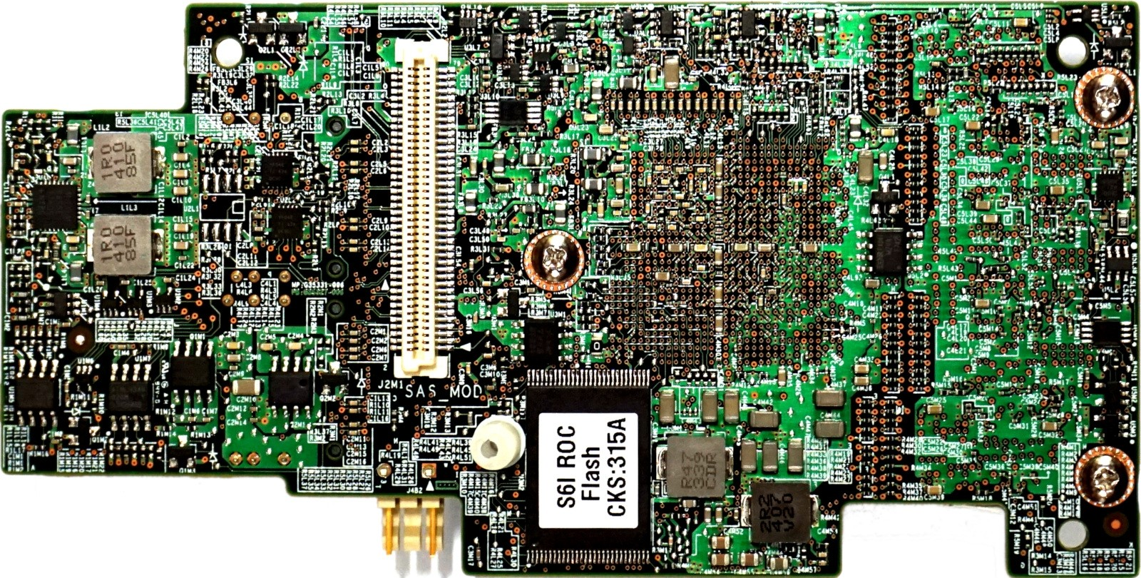
1601562214379.png


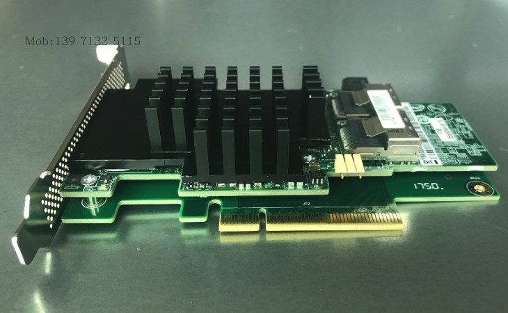
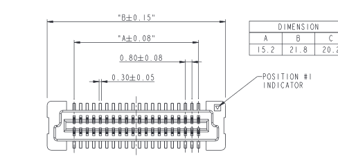
Instead of throwing thrash, I want to use on my NAS server but as you can see it uses 80 pin 0.8mm Pitch Board to Board connector. Its basically PCI-e Gen2 8x connector. I cant find a carrier board for this except this one:

A chinese guy already build everything:
https://www.chinahao.com/product/536165602941/
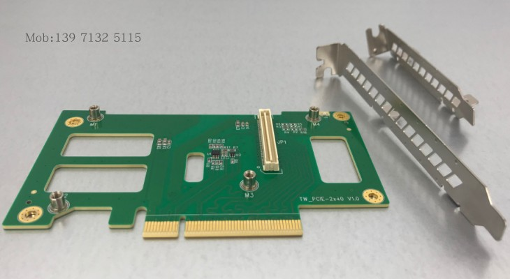
1601562386865.png


1601562453458.png


Unfortunately I cant trust the website and when I try to visit sellers store, it says "store is removed" so I decided to make my own. I found the card pinout table:
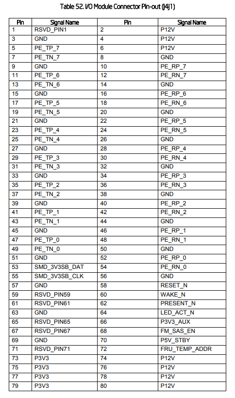
1601562629236.png


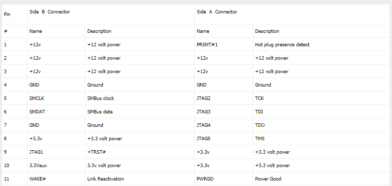
And this is the regular PCI-E pinout
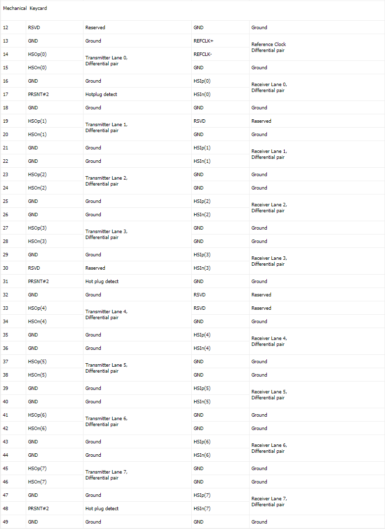
1601562733588.png

1601562764117.png


Here comes my questions:

1- On raid module, I cant figure out which one is side A and which one is side B?
2- On regular serial connections one side RX going other side TX and vice versa. Is this rule applied on here like "card's HSOp matches with motherboard HSOn pin" ?
3- What is the Ref Clock + and - and where its used on the mezzanine card?

Or forgot every question above, can any hardware guru help me to match these pins?
 
1.) If you check out the raid module, you can see which way it's intended to fit on the board... can't you figure it out from the orientation? Or are you talking about the PCIe connector itself?

If you look at your picture of the PCIe card.... that part that is on top is side B. If you basically plug that PCIe card onto your pinout document it lines up properly :). Aka, stand it up on the paper in between the B/A sides with the short part where the case bracket attaches at the top of the paper, then B is on the left and A is on the right just like it is on the paperwork.

I'm not positive what the pinout of the board connector is, knowing the PCIe connector is only 1/2 the issue. You need the pinout for the 80 pin 0.8mm Pitch Board to Board connector or you need to be able to see the traces on the extension board in order to know which pin goes where.

This seems like a lot of work when you can buy a used raid card for under $50 and not have to bother with trying to get a custom circuit board made and testing and chance of frying shit. Also, there are a few components on the extension board as well, youd have to know what those are and how they're connect (or read the pci spec and find out the requirements).
 
Last edited:
1601580839619.png

https://www.intel.com/content/dam/s..._rms25pb080_rms25pb040_rms25cb080_rms25cb.pdf

This is from the spec sheet of the RAID card, you can see the indicator for pin 1, so you should be able to figure out the rest of the pins from there.

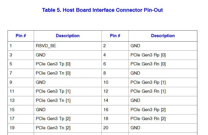
Also, the pinout you reference seems different than what's in the official documentation....

1601581046668.png


This is just a small snip, but you can see this does not line up with your list. Where did you get that diagram and are you positive it's from the same module? Seems there is either something off with your copy or the official intel docs are wrong... but they don't match that's for sure.
 
Also, there are a few components on the extension board as well, youd have to know what those are and how they're connect (or read the pci spec and find out the requirements).

From pin 70 it seems raid card requires 5V Standby voltage and its not included in regular slot. I assumed that components are for (or not). The country I live cant let me buy anything because of ridiculous exchange rates. Even works or smoked, its useless sitting in drawer so I didnt expect anything :)

Ready4Dis

Thats interesting because I took the diagram from one of compatible boards manual, page 88:
https://www.intel.com/content/dam/s...ds/server/sb/g84364004_s1200v3rp_tps_r2_0.pdf

So I made a quick test with multimeter on raid card. From motherboard diagram pin 2, 4 and 6 should be short but not. But according to the diagram you provided, pin 2, 3 and 8 are short so it seems your diagram is correct one. I'm going to re-evaluate. Thanks.
 
Well at least you were able to check! That could make a huge difference (having the right pinout). I'm on my phone now but I can try to give you a hand in some fashion, but was curious, you have the raid card and extension board on hand? If so then it might not be to horrible, but still a lot of work. What exactly are you trying to do though? Make a custom extender board? If you have one to ohm out, did you need another or?
 
Back
Top