ASUS Dual 1070 8GB trips PSU when plugged into PCIE

Blitz54

n00b
Joined
Aug 12, 2022
Messages
6
Hello everyone! New here, it looks like there are lots of smart peeps in this forum so I figured this would be the best place to ask for some help, if anyone is willing to.

So, I got this card from an auction sale. 50 bucks CAD got me the card, an i7 7700k with a strix board, and a bunch of wires and plugs and other goodies. Unfortunately the card doesn't work, but I'm willing to learn some things to see if it's worth it, or even possible to revive the card. I'm not much of an electronics guy. I know more than my friends, I play with arduinos and work on my car with electrical stuff, but 90% of the time I don't understand WHY it works, just that it does. So while I'm not a total newbie, please forgive me for any dumb questions, I'll try my best to limit how many I ask.

Anyway, here are the symptoms/notables
  • card plugged into any mobo PCIE trips the PSU protection
  • card not plugged into PCIE but plugged in with 8 pin doesn't trip PSU, at least not instantly that I saw
  • the white and red led light to sense the 8 pin being plugged in works correctly.
  • card is extremely clean. Can't even find any caked on dust deep in the heatsink.
  • card also came with rubber sleeves for the PCIE and the mounting bracket, as well as caps for the display ports. Doesn't mean much, but it's clean as heck

Things I've "tested" or noticed. Not sure how much of this is valuable info, but maybe it'll help out.
  • the first 3 12v lane/pin (is it called a lane?) on the PCIE has 1ohm to ground. Which I guess is a short. I have a cheapo mastercraft multimeter.
  • the 3.3v lane, fourth from the right most pin, is 160kohm to ground
  • the 12v to ground pins on the 8 pin connector are all 50ohm. Doesn't matter what combination.
  • the 4 MOSFETS near the 8 pin have 3 pins on one side that are bridged together. I have no idea if it's intentional or not, but considering all 4 have that I think probably?
  • no burn marks, no clearly broken parts. Which makes life harder.

I don't really know where to start looking from here on. Some guidance would be greatly appreciated. I'm not expecting to bring this back to life, but I may as well try, and use it as a learning experience. I'm still happy with my purchase regardless, as I still got enough out of it. I'm just so surprised how a card so clean is so dead. Would this be a mining card? I'm assuming theres a good chance, as a good miner would probably have great ventilation which would explain the lack of caked on dust.

Thanks all for reading this. I can provide pics when needed.
 
Just curious if you can provide PSU specs please?

An obvious second question - have you tried swapping GPUs, PSUs(if you have either)or resetting the mobo bios?(only reason I ask for third thing is who knows if previous owner messed with the voltages.).
 
Last edited:
Just curious if you can provide mobo and PSU specs please?

An obvious second question - have you tried swapping GPUs, PSUs(if you have either)or resetting the bios?(only reason I ask for third thing is who knows if previous owner messed with the voltages.).
Funny timing. I just took another look at the card. I actually bought a new PSU for my PC as my old one was a 500w EVGA from 7 years ago. Put in a 750w SuperNova G6.

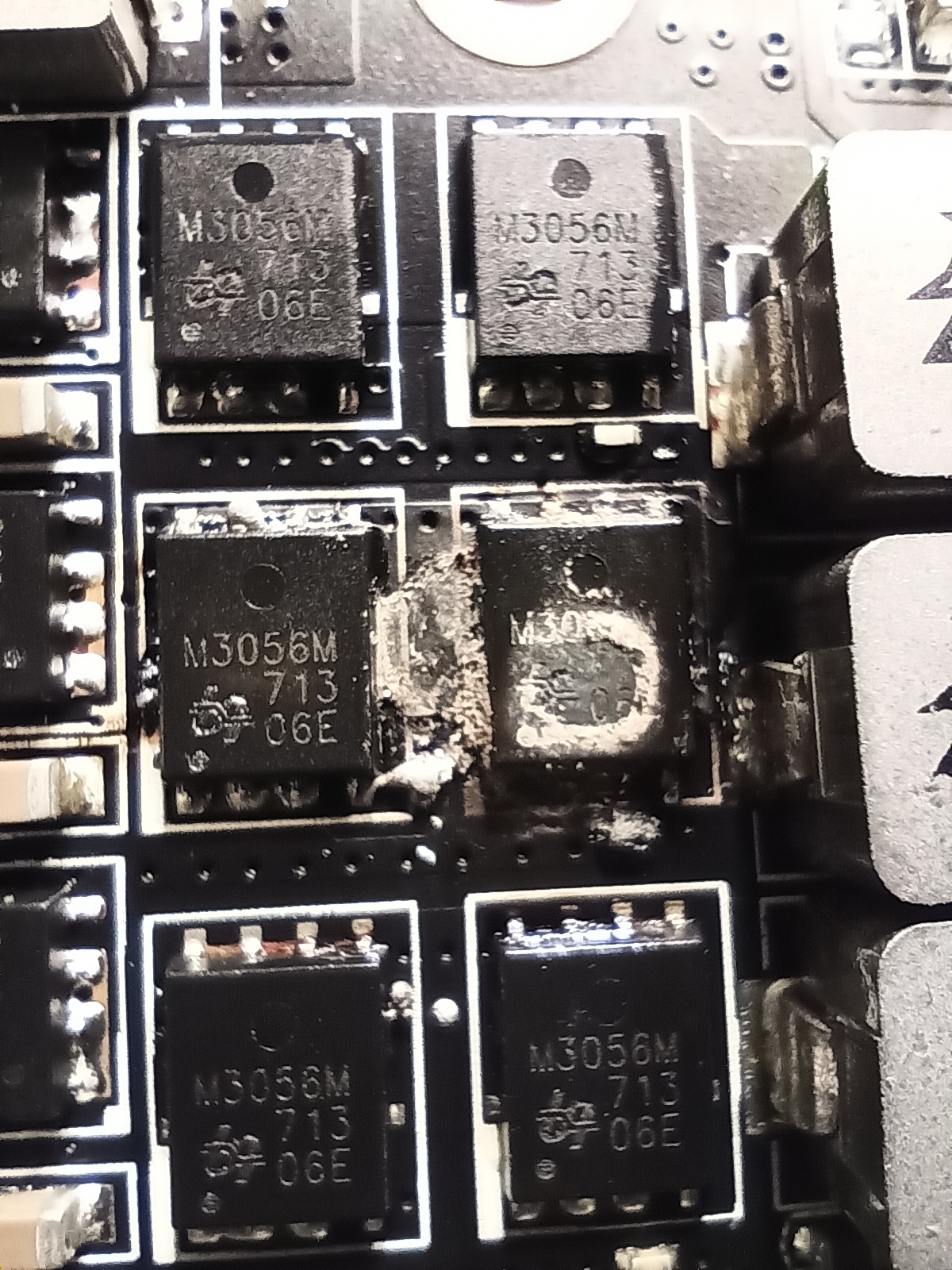
But also, that info is no longer required as I realized I am dumb. I didn't pull off the heatsink to check the stuff underneath. Wiggled it off, and found a slightly burnt MOSFET. Probably took out the one beside it too.

Guess I'll research the rest of this a bit more. Seen lots of people replace them on videos, but some forum posts online say it's a good chance more stuff died.
IMG_20220813_011606.jpg
 
Hello everyone! New here, it looks like there are lots of smart peeps in this forum so I figured this would be the best place to ask for some help, if anyone is willing to.

So, I got this card from an auction sale. 50 bucks CAD got me the card, an i7 7700k with a strix board, and a bunch of wires and plugs and other goodies. Unfortunately the card doesn't work, but I'm willing to learn some things to see if it's worth it, or even possible to revive the card. I'm not much of an electronics guy. I know more than my friends, I play with arduinos and work on my car with electrical stuff, but 90% of the time I don't understand WHY it works, just that it does. So while I'm not a total newbie, please forgive me for any dumb questions, I'll try my best to limit how many I ask.

Anyway, here are the symptoms/notables
  • card plugged into any mobo PCIE trips the PSU protection
  • card not plugged into PCIE but plugged in with 8 pin doesn't trip PSU, at least not instantly that I saw
  • the white and red led light to sense the 8 pin being plugged in works correctly.
  • card is extremely clean. Can't even find any caked on dust deep in the heatsink.
  • card also came with rubber sleeves for the PCIE and the mounting bracket, as well as caps for the display ports. Doesn't mean much, but it's clean as heck

Things I've "tested" or noticed. Not sure how much of this is valuable info, but maybe it'll help out.
  • the first 3 12v lane/pin (is it called a lane?) on the PCIE has 1ohm to ground. Which I guess is a short. I have a cheapo mastercraft multimeter.
  • the 3.3v lane, fourth from the right most pin, is 160kohm to ground
  • the 12v to ground pins on the 8 pin connector are all 50ohm. Doesn't matter what combination.
  • the 4 MOSFETS near the 8 pin have 3 pins on one side that are bridged together. I have no idea if it's intentional or not, but considering all 4 have that I think probably?
  • no burn marks, no clearly broken parts. Which makes life harder.

I don't really know where to start looking from here on. Some guidance would be greatly appreciated. I'm not expecting to bring this back to life, but I may as well try, and use it as a learning experience. I'm still happy with my purchase regardless, as I still got enough out of it. I'm just so surprised how a card so clean is so dead. Would this be a mining card? I'm assuming theres a good chance, as a good miner would probably have great ventilation which would explain the lack of caked on dust.

Thanks all for reading this. I can provide pics when needed.
Based on your photo, you've got a short to ground through one or more of the low side FETs, which is good in the sense that it bypasses the GPU die, so, if you can clear the short, the card will probably still "work." The bad news is that it looks like the dead FETs probably welded themselves to the underlying traces, so the chances of properly fixing this are pretty slim. It's worth a shot, though.

Try removing the two damaged low side FETs, and see if your short to ground on pin 3B of the PCI-E finger goes away. If it does, consider replacing all eighteen FETs. Chances are, some of the other FETs are close to failing as well, and you're likely to damage them further with the heat required to get the dead ones off. A PCB preheater is recommended, but the good news here is that these discrete FETs are way easier to remove and install than a 56pin QFN power stage.
Just the person I was hoping would show up. I didn't want to specifically ask for your help as I'm totally new, but I appreciate you jumping in here too.

I cleaned up around the MOSFETS a bit. The bigger blob basically merging the two together came off easily. But I can see some copper colour underneath the burnt one. Not nearly as bad as some many examples online, but I'm not what makes it "bad" ya know.

I ordered 15 of the MOSFETS. I have no idea what readings I should be getting, or if I was even checking them properly, but I did notice the 2 directly below the 2 damaged ones seemed to give different resistances than the ones farther down. Maybe I should have ordered more, but on my board I have 12 that are labelled M3056M, and the 6 to the left that are perpendicular to the 12, are labelled M3054M. I figured not all would need replacing, and it would give me a little extra, in case I royally screw some up somehow. Worst case I'll have to wait for more.

How necessary would a PCB preheater be? I have a decent heatgun, and just ordered all the stuff I need off Aliexpress, so it'll be a few weeks before I can tackle this. Also just got a nice multimeter in today, perfect timing as my WIP car is all finicky today lol.
 
How necessary would a PCB preheater be? I have a decent heatgun, and just ordered all the stuff I need off Aliexpress, so it'll be a few weeks before I can tackle this. Also just got a nice multimeter in today, perfect timing as my WIP car is all finicky today lol.
If what you mean is an actual heat gun, there is no such thing as a "decent" heat gun for this purpose. The proper tool is a hot air rework station, which is much more precise. You can probably get away without the preheater, particularly if you're using a heat gun, but especially for this type of repair, it would make life an awful lot easier.

The trouble is that, because you don't have a pick and place machine, you have to install the new FETs one at a time, meaning that you're going to subject the first one you install to way more heat, over a much longer period of time, than they're meant to withstand. It may work anyway, but it's not really a proper way to do this, in the same way that using a chainsaw is not the right way to carve delicate bird figurines.
^^^ this. The heat gun only method is going to be seriously challenging OP.
 
If what you mean is an actual heat gun, there is no such thing as a "decent" heat gun for this purpose. The proper tool is a hot air rework station, which is much more precise. You can probably get away without the preheater, particularly if you're using a heat gun, but especially for this type of repair, it would make life an awful lot easier.

The trouble is that, because you don't have a pick and place machine, you have to install the new FETs one at a time, meaning that you're going to subject the first one you install to way more heat, over a much longer period of time, than they're meant to withstand. It may work anyway, but it's not really a proper way to do this, in the same way that using a chainsaw is not the right way to carve delicate bird figurines.

^^^ this. The heat gun only method is going to be seriously challenging OP.
Thanks for the input peeps. I'll definitely look into a hot air rework station. I didn't really think about the accuracy of the heat gun. It has small attachments, but when compared to the mosfet itself I realized how small they really are.

Also, once again I amazed myself with my own stupidness. Ordered stuff on Aliexpress, bought some solder wick, a solder sucker, some tweezers and small tools to work with, and a precision knife kit. Just to realize I HAD THOSE ALL in the soldering iron kit I bought last year... I only used the soldering iron once for something quick and easy, so I didn't use the other stuff and totally forgot about it. Oh well, spares won't hurt. Until I buy a third set.
 
I had the same problem with my 980 Ti and I was able to fix it by removing the 2 bad mosfets. I damaged the pads on one of them so I decided not to replace them. To my surprise the card has been working for over a year now at stock clocks. No stability issues.
Replacing them will be very difficult without prior experience with SMD parts. Removing them should be doable though, so it's definitely worth a shot. I used a cheap heat gun from ebay by the way.
Sorry, what do you mean by pads? So you just removed them and didn't replace? How exactly does that work. Will the card just run slower/less stable at higher clocks? When I remove them I'll upload a pic of the board underneath, for suggestions on where to go from there.
 
Sorry, what do you mean by pads? So you just removed them and didn't replace? How exactly does that work. Will the card just run slower/less stable at higher clocks? When I remove them I'll upload a pic of the board underneath, for suggestions on where to go from there.
The pads are the exposed copper on the board where the pins attach to. Too much heat can damage them making it hard if not impossible to solder a new mosfet.

Yes I removed two of them and did not replace them. The VRMs are designed with plenty of headroom most of the time. Each mosfet can handle much more current than they will actually need to provide under regular conditions. If one or two mosfets are missing then the remaining mosfets need to work harder, but they can handle it as along as temps are good. You might need to underclock but I'm able to run mine at stock clocks just fine.

And sure upload a pic and I'll try to help as much as I can.

edit: Also there are different VRM designs depending on the exact GPU, so this may or may not work in your case, but there's a good chance it will, although I'm not an expert in GPU repair.
 
Last edited:
So I got the parts I needed. Unfortunately it's a struggle for me.

That first one that was blown up is "off". But so is most of the pad underneath... is what it is. This is a learning experience at this point after all.

However, I don't understand what the heck I'm doing wrong here. I need to remove a few others, as it seems a few others are shorted. Most read 10k where they are supposed to, but almost one on every lane read 0 or 50 ohm. Of the 6 lanes I think 2 read good on all 3 MOSFET. Maybe I screwed it up, but again, whatever, learning. When I tried to remove another MOSFET, I literally could not get the thing to budge. I have the hot air rework station at 350 from what I read in a few posts. But the board starts to get uncomfortably hot before any sign of it giving way. I don't want to burn something up, so I stopped to come here and ask you guys.

Is 350 too low? I really didn't expect it to be such a pain to remove the nicer looking components after watching a bunch of videos.

Thanks peeps.
 
Ok, first, there are multiple circuits in the bank of VRM phases on this board, and it matters where on each one you probe. To check if you cleared the short, you need to check on the 12V input pins from the power supply. If you're checking the resistance at the VRM switch nodes, the resistance you're seeing is the static resistance of the logic circuit. The 50 ohm one is probably the memory, and the "0" ohm one is most likely the GPU. For each power circuit, the switch nodes are all connected together, so you'll get the same resistance to ground on each phase, regardless of which one is shorted or which one you probe.

Regarding the heat, yes, you need more heat. I usually set mine to 400 or 425, and it takes for-ev-er to heat up a VRM section to the point where you can remove a big SMD mosfet. That part of the board is deliberately designed to act like a heatsink, so you're working against that as you try to heat it up to the point where the solder melts. Keep in mind that you have to get the solder up to about 230 degrees celsius before it will melt. It will be waaaaaay too hot to touch with your fingers. You'll need a pair of real fine tweezers to manipulate the components once the solder melts. Are you using flux? It will eventually melt without flux, but it will be a lot easier with flux.

A preheater would reduce the time you have to spend heating the board with the wand considerably. You use it to heat the whole board up to about 180 degrees, and then zap the components on and off with a few seconds of the wand at high temperature. This reduces the chance of killing the new components you install by overheating them in the process of installing, too.
 
Back
Top