Anyone have any experience with Amplifier Troubleshooting and Repair?

Zarathustra[H]

Extremely [H]
Joined
Oct 29, 2000
Messages
38,819
Hey all,

Almost 2 years ago, I picked up an Emotiva UPA-2 amp used on craigslist.

Up until today it had been working perfectly, until without warning the left channel just stopped working. The unit has not been dropped banged or mishandled in any other way, so the sudden loss of the left channel is perplexing me. I might have pushed it back against the wall and put pressure on one of the RCA inputs.

Currently I have it set up like this:
Schiit Modi Multibit DAC -> Sys Preamp (used as source switch) -> Schiit Jotunheim Headphone Amp (used both for headphones, and as pre-amp for the UPA-2).

I also have the line outs on my UPA-2 hooked up to my Subwoofer.

I just don't have sound out of the left channel, but the little blue LED's on the front of the UPA-2 that indicate the channel is operational are both on.

So, I have started troubleshooting:

- First I checked the connections to my speakers to see if they had come out (they hadn't).

- Then I decided to check if it was my source or the amp that was acting up, by listening to my headphones. The headphones have sound on both channels, so the problem is downstream from the Jotunheim headphone amp.

- Next I noticed that the Subwoofer also does not play any sound when there is input on the left channel.

- Next I swapped the inputs. The test singnals now play the left channel sound on the right channel, so it's not the pre-amp or wires, but something in the amp itself, and whatever it is, is preventing the signal both from reaching the internals of the amp, and from reaching the subwoover.

My theory now is that somehow, something on the inside of the amp has become disconnected, possibly on the inside of the binding posts.

Does this sound reasonable?

I'm unplugging the amp right now to let the caps discharge over night, and then tomorrow I plan on opening it up to see if I can see anything obvious wrong with it.

Does anyone have any further suggestions? Any further tests I should do? Any cautions? I am not a stranger to electrical stuff or soldering, but I have never worked on an amp before.

Any help anyone can provide would be greatly appreciated.

(Side note, these posts are going to come in rapid succession, as I ahve done a lot of troubleshooting, and I am catching up with the forum posts)
 
Last edited:
So,

I cracked it open and now I'm looking inside. I was hoping to see something obvious, but I don't

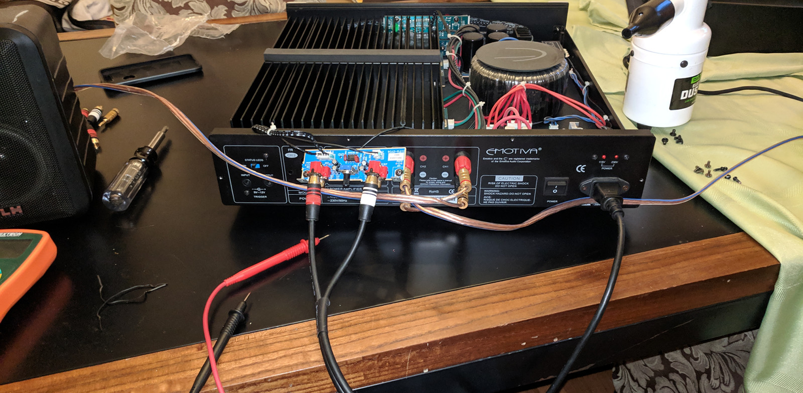
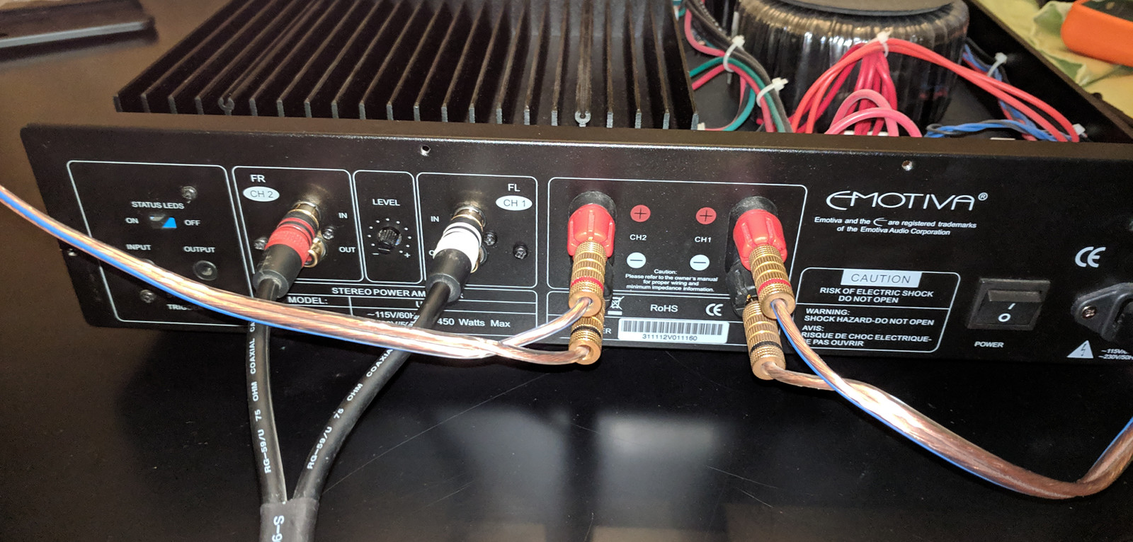
Some pictures (please excuse the dust, looks like I am going to have to blow it out before reassembling) You should be able to click on them for the full size.

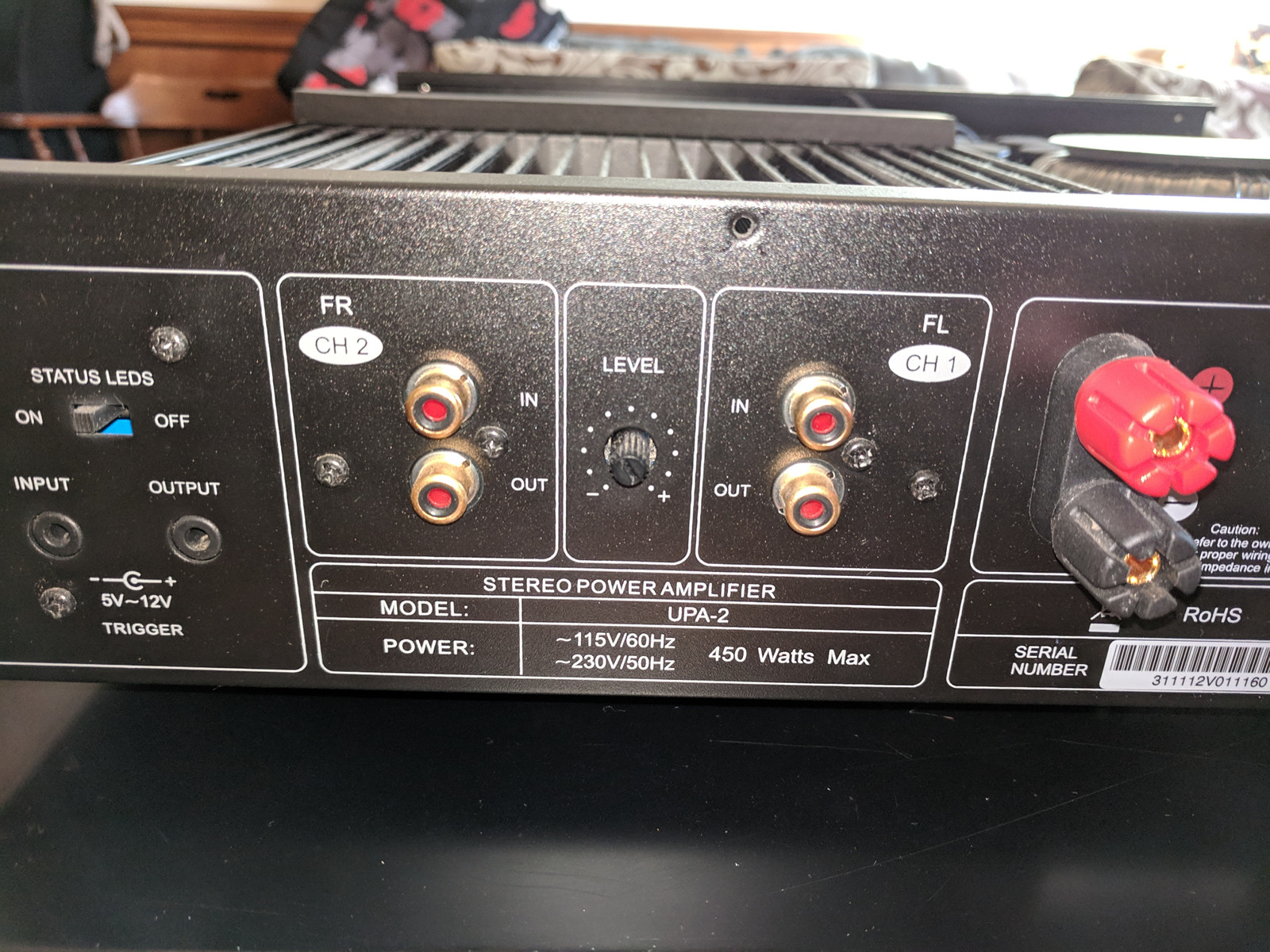
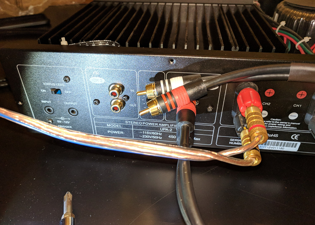
Back of unit:

01-sml.jpg


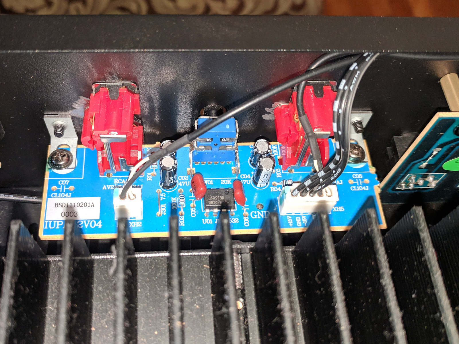
Input PCB attached:

02-sml.jpg


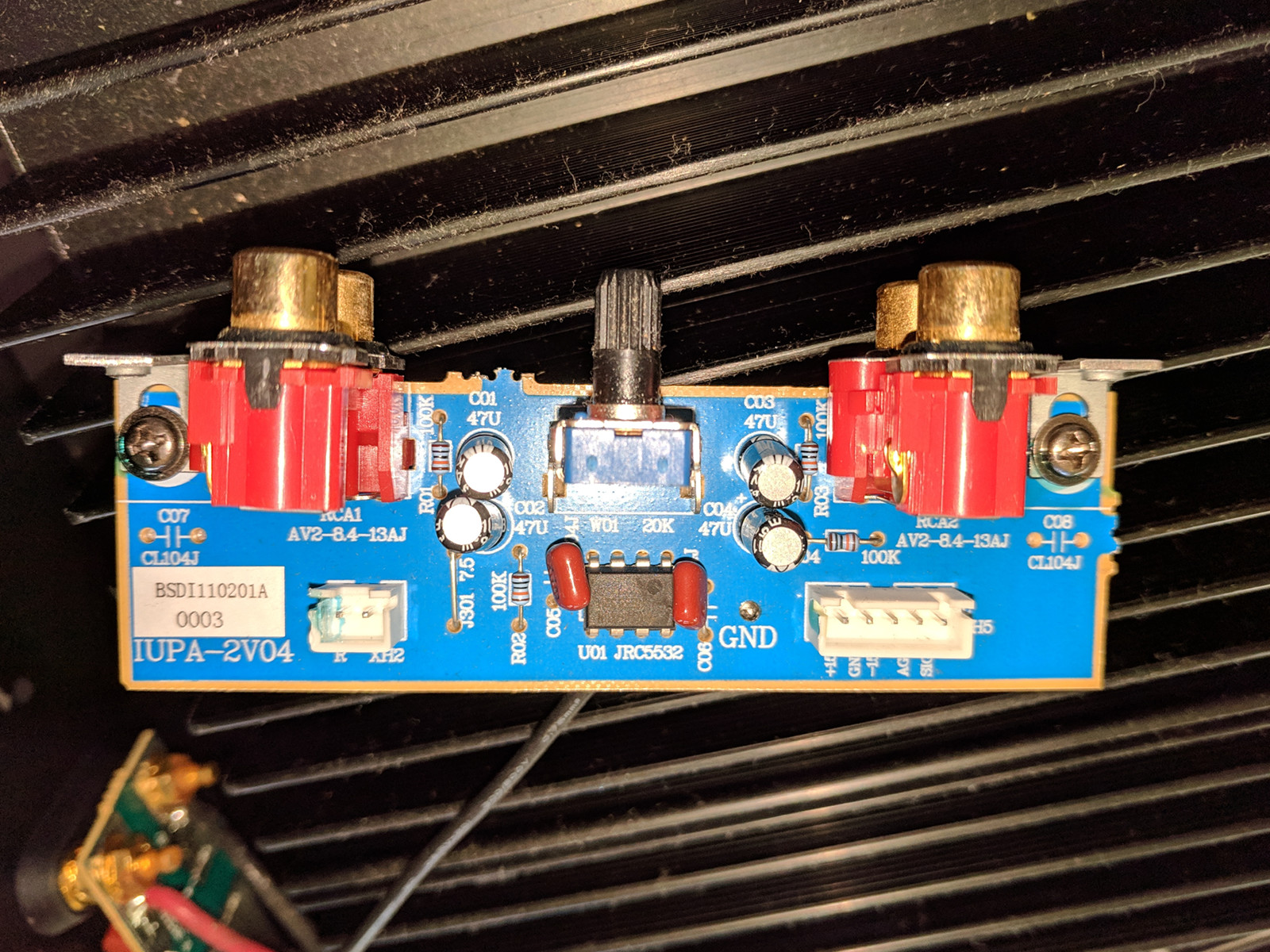
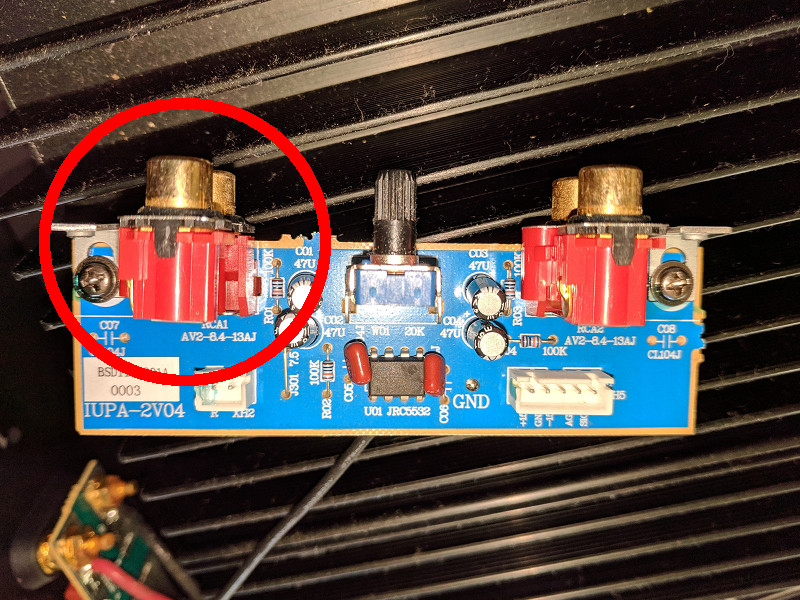
Input PCB Removed, Top:

03-sml.jpg


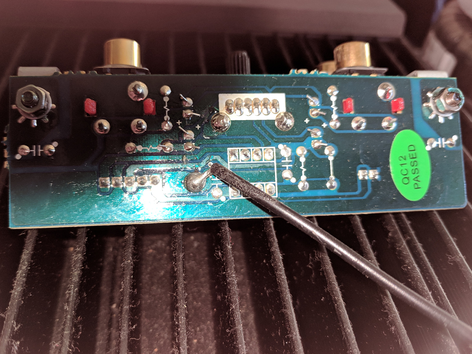
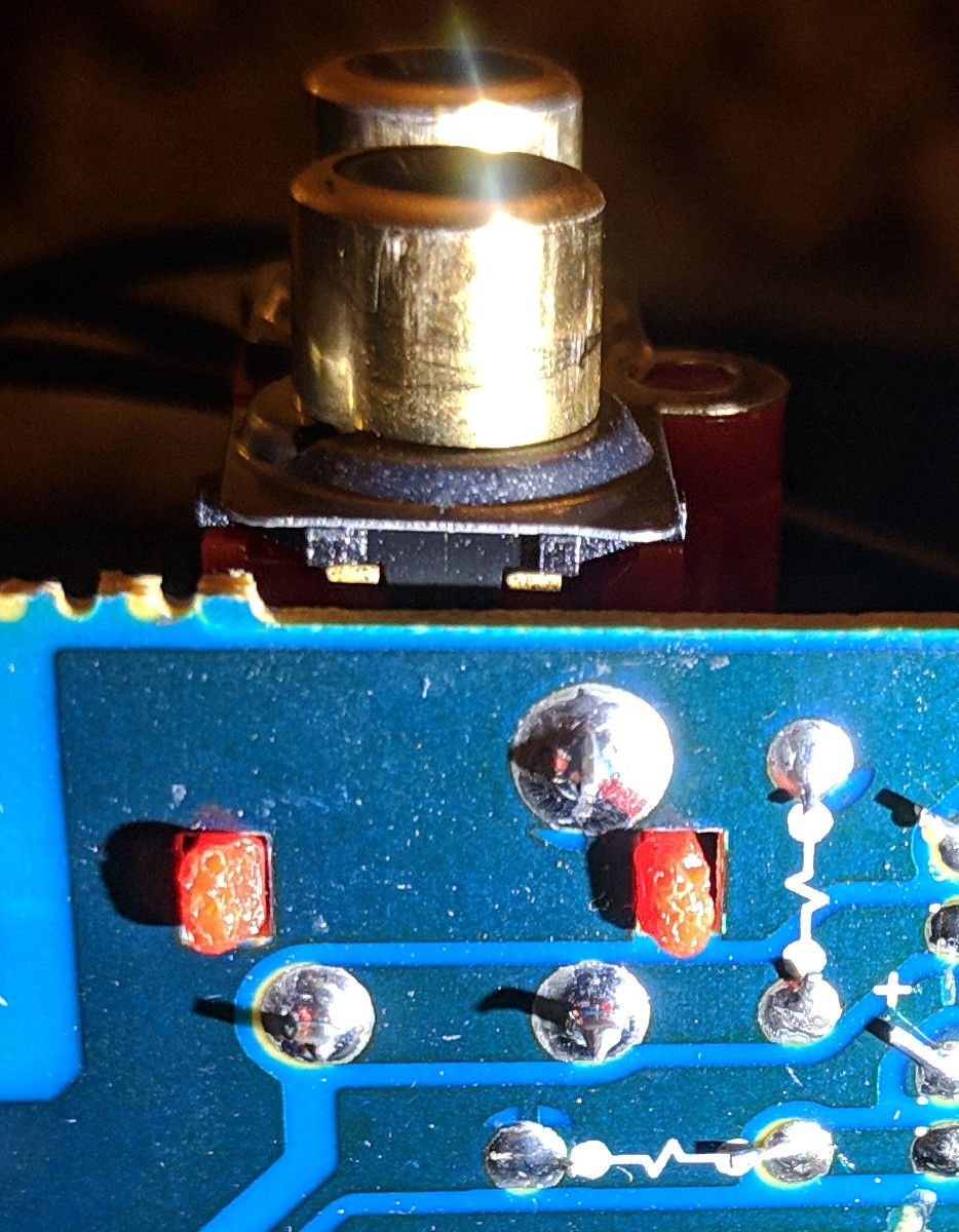
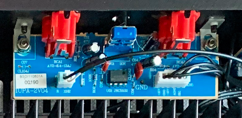
Input PCB Removed. Bottom:

04-sml.jpg


I feel about 95% certain the issue is somehow with the input PCB. I guess it is time to crack out the multimeter and do some continuity testing.
 
Hmm.

Went over the continuity on the input board and it checked out, but after assembling everything together again, I have the same problem.

I tried with a different source and different cable, and the same. Then I jiggled the RCA cable on the back, and the left channel popped in and out for a fraction of a second.

So, it's definitely some sort of problem or intermittent contact on the input board, but where on the board? It's so weird that continuity checked out and then it didn't work when plugged in.

I wonder if I can buy a replacement input board. I'd have to solder that ground wire on the bottom... I hate PCB soldering (my hands aren't the steadiest),but that one doesn't look TOO difficult
 
Alright,

The mystery deepens.

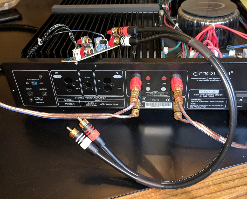
Both channels work if I remove the board and run it outside the case. (Side note, touching the wrong with with the case opened and powered on can kill you. Don't do this :p )


works_sml.jpg


Then, when I assemble the board back into the case, the left channel stops working again:


doesnt_work_sml.jpg


At least this explains why my continuity tests worked when I had the board out...
 
My first thought was that maybe the solder joints at the base of the connector had cracked, and the pressure from being tightened to the case was pushing them in just the right way to break contact.

My next thought was maybe I should reflow those solder joints with my soldering iron in order to fix it.

Looking at the three joints that connect the RCA connector to the board though they look in perfect condition.

solder_joints_sml.jpg
 
Some further testing that confirms the "works when not installed in chassis, but fails when installed in chassis" problem.


Plug in RCA connector with board out:

works2.jpg


Since the input and output are supposed to be electrically connected, we would expect the following:
Test continuity from ground to ground: Checks out fine.
Test continuity from center pin to center pin: Checks out fine.

This aligns with the fact that the left channel worked just fine in functional testing when the board was out of the chassis.

Now, lets do the same with the board assembled into the chassis:

doesnt_work2.jpg


Test continuity from ground to ground: Checks out fine.
Test continuity from center pin to center pin: Fails. No continuity.

This also aligns with the fact that the board works when out of the chassis , but not when installed, in functional testing.

So, it really sounds to me like there is an intermittent connection, and that the physical stresses of being tightened to the chassis is what is breaking the connection on the center pin.

Now the only question is where it is. My guess is inside the RCA block, but I can't prove it yet.

03-sml-circled.jpg


Does anyone know if this dual RCA block is a standard part I can buy and replace somewhere?
 
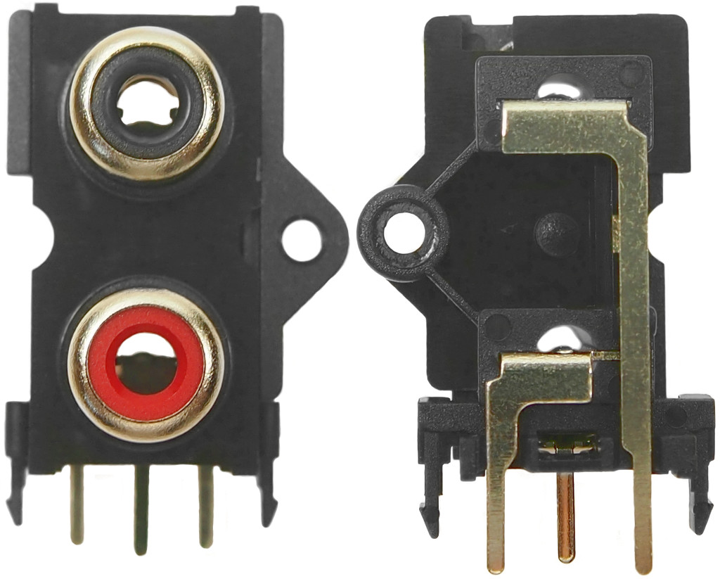
After some further research, it looks like what I might be dealing with is a custom all red version of a part with the part number FC684052.

attachment.jpg


It looks like the part I found is designed for stereo use, not for bridged use, but examining the Emotiva board, it appears it is electrically and physically the same, just different colors, and that the two connectors are bridged on the board...

Anyone have any thoughts?
 
My first thought was that maybe the solder joints at the base of the connector had cracked, and the pressure from being tightened to the case was pushing them in just the right way to break contact.

My next thought was maybe I should reflow those solder joints with my soldering iron in order to fix it.

Looking at the three joints that connect the RCA connector to the board though they look in perfect condition.

View attachment 140991


Any luck with your amplifier?

I'd have those points re-soldered if you haven't done so yet. You can also put a small amount of silicon grease to your connections so they'd slide in with little resistance. This resistance over time probably caused small cracks in the solder points.
 
Any luck with your amplifier?

I'd have those points re-soldered if you haven't done so yet. You can also put a small amount of silicon grease to your connections so they'd slide in with little resistance. This resistance over time probably caused small cracks in the solder points.


Thank you, no, unfortunately not yet.

My desktop caught fire so I was distracted with that.

It's back on my list now.

I'm starting to think that all I am dealing with is a bent strip on the inside of the RCA block. The one that makes contact with the RCA center pin.

It's tough to tell though.
 
Oh man, I just checked out your other thread. You have some odd luck there!

Maybe then a replacement RCA block would solve your issue? If that doesn't work, then we can try other solutions. I hope you can sort it out, best of luck!
 
Oh man, I just checked out your other thread. You have some odd luck there!

Maybe then a replacement RCA block would solve your issue? If that doesn't work, then we can try other solutions. I hope you can sort it out, best of luck!


Do you have enough experience to know which RCA block I would get?

I found one online which looked right, but then when I looked at the pin location drawing, the dimensions were all off, and it did not look like it would work.


Do you know if these are standard catalog parts I can get somewhere?
 
The RCA in and out are just parallel connections from what I can see- use the left RCA as your input and test.

I'd also reflow those solder joints just to be sure.
 
Do you have enough experience to know which RCA block I would get?

I found one online which looked right, but then when I looked at the pin location drawing, the dimensions were all off, and it did not look like it would work.


Do you know if these are standard catalog parts I can get somewhere?

I've never had a need to change an RCA block so I have not experienced in changing one, I wish I could be more helpful. Maybe another broken amplifier would have the same RCA block, simple de-solder and out it goes.
 
Zarathustra[H] Did you get anywhere with this? I noticed that Switchcraft offer dual RCA blocks which appear to have the same mounting pin arrangement as pictured.
 
Zarathustra[H] - have you tried gradually tightening the board while it is in the system to see at what point the disconnection occurs? Can you physically see a difference anywhere from when it works loose to when it is tight?

Also, it looks like both the left and right RCA block are identical, if your skills are up to it, I'd be tempted to put the Right Known working connector on the left and do the same tests, that would rule out any issues on the board and confirm the RCA is at fault.

Also, Have you contacted the manufacturer of the AMP? https://emotiva.com/pages/support They may stock a spare or at least be able to tell you the part number so you can find one.
 
Last edited:
Zarathustra[H] - have you tried gradually tightening the board while it is in the system to see at what point the disconnection occurs? Can you physically see a difference anywhere from when it works loose to when it is tight?

Also, it looks like both the left and right RCA block are identical, if your skills are up to it, I'd be tempted to put the Right Known working connector on the left and do the same tests, that would rule out any issues on the board and confirm the RCA is at fault.

Also, Have you contacted the manufacturer of the AMP? https://emotiva.com/pages/support They may stock a spare or at least be able to tell you the part number so you can find one.


Very good suggestions. Thank you. I will try those. I've been tied up with some other more pressing projects, so I haven't had time to spend on this lately.

I did try contacting Emotiva, and I'm really quite disappointed in them. They don't sell any spare parts at all to individuals or 3rd party repair centers. The only way to get anything from them is to ship them the whole thing and pay their service fee and shipping, which will easily exceed the replacement cost of the amp.

I originally reached out to them thinking I could simply get a replacement input board and just do a drop in replacement. It looks simple and cheap enough, but no dice.

Based on this I don't see myself ever buying anything Emotiva again. if they won't even sell me spare parts it is clear they don't stand behind their stuff.
 
Last edited:
Alright. Install the input board and do a continuity check to ground from every contact. I have a feeling that your signal is getting grounded out.
 
I just saw this thread and I wanted to say one thing. As other already mentioned I think it would be a good idea to reflow the solder connections of those RCA blocks. I can almost SEE the cold solder cracks in the pics of the bottom of the input pcb. Heat the three terminals and a small amount of rosin core solder(imo avoid acid core), even a novice at soldering can do this easily - just don't overheat the pcb or you risk damage to the copper.
.... and when testing please put something between the bottom of that pcb and the metal heatsink !!.... :p
 
Unfortunately not yet.

Work has been crazy, and I was just too exhausted last weekend to deal with it.

It's still #1 on my to-do list though, and I will post back here with any updates.

Hi Zarathrustra,

Did you ever solve your problems with this board? I have a UPA-2 as well, and while my input board does not have any issues, I am contemplating removing the board from the amp and going directly to the amp modules. I don't need an input level control, and I believe that bypassing that little opamp will help improve sound quality.
 
No, unfortunately not. I got the opportunity to buy a Parasound amp for my office at a very good price, so I didn't need the amp anymore. I put it in storage.

My plan was to either sellmit cheaply or give it away and let someone else try to repair it.
 
You can usually find a comparable RCA input on Mouser or DigiKey. I agree with posters above, simple reflow should do the trick. You probably can't see cold solder cracks.
 
While I'm not having problems with the board that Zarathrustra has having so much trouble with, I am thinking of removing it to improve sound quality. It uses a cheap little opamp chip to control input signal. I am thinking that getting this out of the low level signal path could be a good idea. The input signal adjustment feature is great if you need to level match this amp with others, but since I plan to run it as a two channel amp in a two speaker system, I don't see the need for it.

Anybody see any reason that removing this little board and going straight to the amp boards with the low level signal wouldn't work? It looks self contained, and I can easily identify the left and right input leads.

Screen Shot 2020-03-20 at 8.57.32 AM.png
 
Back
Top