David Deyarmin
n00b
- Joined
- Mar 11, 2018
- Messages
- 11
used to build computers in the 90s but then work got in the way so from the early 2000s til just recently I bought off the shelf units for productivity work and some light gaming.
When my most recent HP AOI died and I bought a simple economy gaming computer to replace it but I had to migrate the guts over to a slim line mid case which meant I had to do some research and I discovered a whole new world of case modding, which reignited my desire to build.
After looking at builds all over the net I decided I wanted to do something different.
A lot of builds concentrate on the cooling system or some extravagant themed case.
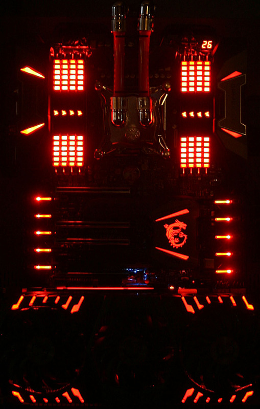
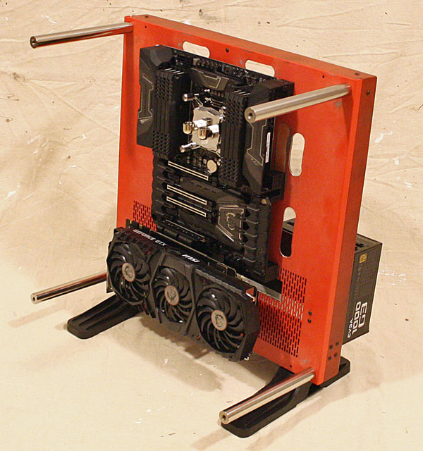
I wanted to showcase the actual hardware and I wanted to do it in a balanced minimalist way with the MB and GPU on the front and the power supply and liquid cooling system on the back
I started with a Thermaltake Core P3 Chassis

To make this work I had to rotate the chassis 90 degrees and use the back as the front which required a lot of internal and external modifications to the metal chassis
 http://s131.photobucket.com/user/BobaDebt/media/Computers/Core P3 003_zpsttkukeow.jpg.html
Final Assembly has begun

http://s131.photobucket.com/user/BobaDebt/media/Computers/Core P3 003_zpsttkukeow.jpg.html
When my most recent HP AOI died and I bought a simple economy gaming computer to replace it but I had to migrate the guts over to a slim line mid case which meant I had to do some research and I discovered a whole new world of case modding, which reignited my desire to build.
After looking at builds all over the net I decided I wanted to do something different.
A lot of builds concentrate on the cooling system or some extravagant themed case.
I wanted to showcase the actual hardware and I wanted to do it in a balanced minimalist way with the MB and GPU on the front and the power supply and liquid cooling system on the back
I started with a Thermaltake Core P3 Chassis

To make this work I had to rotate the chassis 90 degrees and use the back as the front which required a lot of internal and external modifications to the metal chassis
This included removing most of the original front panel, relocating all of the internal brackets and filling a lot of holes.
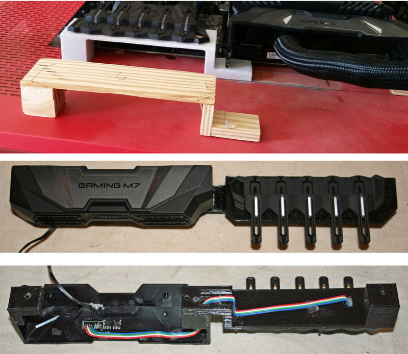
I also had to add the mounting holes for the MD stand offs and several pass through slots for the wiring.
The chassis mods are about 90% done and should be ready for paint by the middle of the week.
I also had to add the mounting holes for the MD stand offs and several pass through slots for the wiring.
The chassis mods are about 90% done and should be ready for paint by the middle of the week.
Final Assembly has begun

http://s131.photobucket.com/user/BobaDebt/media/Computers/Core P3 003_zpsttkukeow.jpg.html
Attachments
Last edited:


")

 [/URL
[/URL