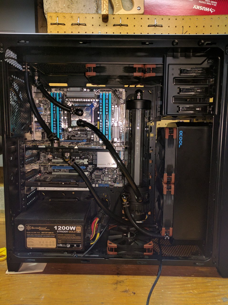
So, I finally ordered parts for my first WC build!

Hmm. This new unplanned tube routing is going to require some sort of bend coming out of the front radiator in order to reach the pump, but this XSPC 45 degree fitting is too short to get around the fan...

View attachment 6719


Nope, the routing just is not going to work with the radiator in this orientation. I'm going to try to figure out a way to mount it upside down. It's probably drill-n-pray time...
 
Last edited:
Hmm. This new unplanned tube routing is going to require some sort of bend coming out of the front radiator in order to reach the pump, but this XSPC 45 degree fitting is too short to get around the fan...

View attachment 6719
Looking good so far. They do have extensions you can buy which probably cost way more than they should, but I guess you're trying to do this with what you already have?

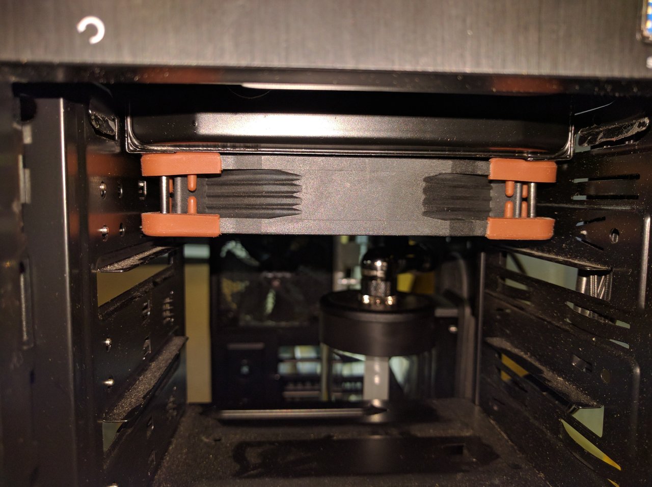
Also, maybe it's just the angle of the photo, but it didn't look like you needed to bend those tabs in the drive bay. I mean, the fans clear them by about 3mm on either side, looks like the radiator doesn't stick out that far. Not that it really matters at this point. :p
 
Looking good so far.

Thank you sir!

They do have extensions you can buy which probably cost way more than they should, but I guess you're trying to do this with what you already have?

Well, if I absolutely need to, I will get more parts, but I just don't want to wait for any more shipping at this point. I started buying parts over a month ago. My urge to build and get it done is intense :p

That, and I really liked my plan for the original tubing routing, so I guess I only needed a little bit of persuasion to try it again.

Also, maybe it's just the angle of the photo, but it didn't look like you needed to bend those tabs in the drive bay. I mean, the fans clear them by about 3mm on either side, looks like the radiator doesn't stick out that far. Not that it really matters at this point. :p


That is possible, if you can get it in with the tabs straight, but I couldn't. I was angling that thing every which way to get it into place, and I kept running into those two tabs.

Actually, I took another look at it, and I ave to take that back. Cell phone cameras have small sensors and ridiculously wide angle lenses that distort everything, but maybe this picture is better. The tabs underneath in this pic are the same size as the ones I bent back, and there is definitely a ~2mm overlap on each side.

IMG_20160815_233402.jpg


I appreciate your feedback. I'm learning as I'm going here, and will take as much advice from water cooling veterans as I can get!
 
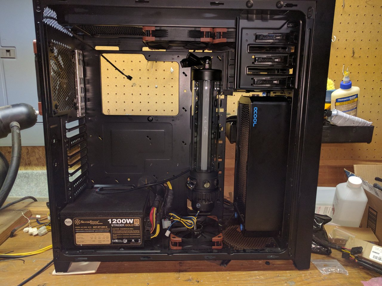
Alright, so I created a stencil of the radiator and its screw holes on a piece of cardboard I had handy, and used that to drill some holes. Got them slightly off on the first try, but widened them with my dremel, and was finally able to fit the front radiator in the orientation I wanted.

I wore my safety glasses, but I probably should also have worn hearing protection. DAMN was that dremel loud on the sheet metal.

I also drilled some holes to mount the reservoir. Unfortunately due to cable passthrough holes in the back plate of the case, there is no way at all to mount this reservoir with all 4 mounting holes. Right now, I have drilled one hole up top, and two on the bottom, and it feels really damned sturdy. I'm hoping it stays that way, or I'll need to make my own bracket to cover the cable passthrough hole so I can tighten down the 4th screw!

IMG_20160815_234220.jpg


Even though I measured it (apparently not very well) I have less space than I anticipated between the top of the reservoir and the fan.

I had planned on putting a bifurcation there and filling the system right on top of the reservoir.

Due to space constraints, is there any reason why I cant fill the system from my intended bleed port up top?

Anyway, I've been working in an un-airconditioned basement during a heat wave for 6 hours. This is taking MUCH more time than I had thought it would. I had hoped to get more done today, but I think I'm going to call it a night and pick it back up tomorrow.
 
I also need to get more canned air so I can blow out all the dust from my drilling and grinding that's everywhere inside the case now...
 
Due to space constraints, is there any reason why I cant fill the system from my intended bleed port up top?
May need to do some tilt-action, but there shouldn't be a problem as long as the pump is covered with water when you turn it on. The water should make it's way to the reservoir eventually, though obviously the more components it has to pass through the longer it'll take. Depending on how you route everything, just laying the case on it's front might work out pretty well for filling and bleeding.
 
Side note:

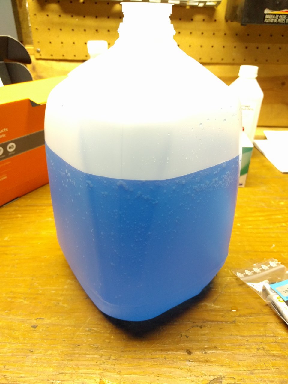
I mixed my Ekoolant. I decided to go with two liters of clear and one liter of IV Blue mixed for a light blue.

With a third of the dye normally used I expected it to be lighter, but it is still pretty dark!

IMG_20160815_165552.jpg
 
Alright, so I created a stencil of the radiator and its screw holes on a piece of cardboard I had handy, and used that to drill some holes. Got them slightly off on the first try, but widened them with my dremel, and was finally able to fit the front radiator in the orientation I wanted.

I wore my safety glasses, but I probably should also have worn hearing protection. DAMN was that dremel loud on the sheet metal.

I also drilled some holes to mount the reservoir. Unfortunately due to cable passthrough holes in the back plate of the case, there is no way at all to mount this reservoir with all 4 mounting holes. Right now, I have drilled one hole up top, and two on the bottom, and it feels really damned sturdy. I'm hoping it stays that way, or I'll need to make my own bracket to cover the cable passthrough hole so I can tighten down the 4th screw!

View attachment 6726

Even though I measured it (apparently not very well) I have less space than I anticipated between the top of the reservoir and the fan.

I had planned on putting a bifurcation there and filling the system right on top of the reservoir.

Due to space constraints, is there any reason why I cant fill the system from my intended bleed port up top?

Anyway, I've been working in an un-airconditioned basement during a heat wave for 6 hours. This is taking MUCH more time than I had thought it would. I had hoped to get more done today, but I think I'm going to call it a night and pick it back up tomorrow.

It's not clear to me where your air bleed port is, but assuming it's on the top of that upper radiator, yes, you can fill that way. You will need to fill very slowly, so air can escape out the same hole. If the bleed port is on the side of the case, you'll need to attach a hose with a fitting to the port, and put the end of the hose higher than the highest point in the system.

You're looking good so far. I have the shorter version of that reservoir. It's a pain in the ass to fill, as the little central column thing blocks the fill port on the inside. This may or may not be a problem for you, as you're not going to put a funnel right there, but the interaction of the air and coolant inside the reservoir makes actually getting the thing filled tricky.

Alternately, loosen one of the plugs on the bottom of the reservoir as you put the first half liter or so of coolant in. This will allow air to escape, but you'll have a little leakage.
 
Looking good. Unexpected nonsense always comes up when building these things.

You have way more rad than you need, but a little overkill never hurt anyone (except in the wallet).

I really recommend not using dye. Clean distill + kill coil is the way to go.
 
Looking good. Unexpected nonsense always comes up when building these things.

You have way more rad than you need, but a little overkill never hurt anyone (except in the wallet).

I really recommend not using dye. Clean distill + kill coil is the way to go.

That was my initial theory as well. I actually bought the silver kill coil before I changed my mind.

I ran the numbers. According to my calculations the Silver actually is what exacerbates things. According to engineering guidelines, in wet worst case environments (like I assume the inside of a loop to be) you want your ΔV to be no more than 0.15. While the ΔV between Copper and Nickel is only 0.05V, the ΔV between Silver and Copper is 0.20V and between Nickel and Silver is exactly 0.15, which leaves no safety margin.

This is certainly not as bad as aluminum which would have a ΔV to silver of between 0.55V and 0.80V depending on the type of aluminum, but it is still too close for comfort IMHO.

Higher ΔV values will lead the metal at the anode to slowly corrode and deposit on the cathode. The anode in these cases would be the copper, nickel and aluminim, the cathode, the silver. You could put a sacrificial zinc coil or something like that in there to counteract the effects, but this would likely leave a mess of zinc oxide in your loop, which wouldn't be desirable.

These are certainly marginal and PROBABLY ok, but given the history with Nickel coatings in EK blocks I decided to err on the safe side, skip the silver, and use their coolant with their added corrosion inhibitors. it might even wind up performing better since they also have a surfactant in their coolant, which you wouldn't get in just plain distilled water. With less surface tension, you make better contact with the inside of the blocks, and transfer heat more effectively.


I debated making my own mixture of algicide, corrosion inhibitor and surfactant, but decided I didn't udnerstand the chemistry well enough to know which ones would react with eachother and which wouldn't, so I decided to just go with a commercial solution, and what better solution than EK's since if any solution is goodf with EK's blocks, it's probably their own :p

I wasn't going to add any color, but I figured since I'm buying the stuff anyway, I'll get one bottle of colored coolant and two bottles of clear and mix them so I just have a light color, which should make it easier to spot leaks during leak testing. Even with the color diluted, it would up being darker than I expected.
 
Last edited:
Surfactants/friction modifiers also aid in reducing hydraulic friction, thus heat generated by the water moving against itself as well as the tube, blocks, etc...
 
Oh, you've got the nickel coating versions - I didn't realize that.


Yeah, I only realized EK had a nickel coating issue in their history after I had ordered the first block, my CPU block. I got nickel because it is supposed to be more tarnish resistant. I know they have a new process now and it is not really an issue anymore, but I still wanted to err on the safe side. When I got around to buying my GPU block, I went with Nickel as well, because I figured I already had it in there, and GPU blocks see much shorter use than CPU blocks typically do.

The interesting part is that if you look up the anodic index tables, Nickel is actually less anodic than copper, so less likely to corrode in a loop with silver than copper is. I'm guessing the reason EK had problems was because their nickel coatings were too thin, and as such even a tiny amount of corrosion became a problem.
 
Surfactants/friction modifiers also aid in reducing hydraulic friction, thus heat generated by the water moving against itself as well as the tube, blocks, etc...

Interesting. I would have anticipated the lower friction leading to better flow rates, but I didn't think it would be a significant contributor to loop heat.
 
Yeah, I only realized EK had a nickel coating issue in their history after I had ordered the first block, my CPU block. I got nickel because it is supposed to be more tarnish resistant. I know they have a new process now and it is not really an issue anymore, but I still wanted to err on the safe side. When I got around to buying my GPU block, I went with Nickel as well, because I figured I already had it in there, and GPU blocks see much shorter use than CPU blocks typically do.

The interesting part is that if you look up the anodic index tables, Nickel is actually less anodic than copper, so less likely to corrode in a loop with silver than copper is. I'm guessing the reason EK had problems was because their nickel coatings were too thin, and as such even a tiny amount of corrosion became a problem.

If I recall correctly, the issue was exclusively with EK's defective nickel coating but they tried to blame people using kill coils and things of that nature. Don't really remember for sure, though, it was a while ago.
 
Looking back at some of these pictures, it's funny how flash cameras catch dust.

My case looks pretty dusty, though in person I couldn't see any. It's going to need a good wipe down once I am done with all my drilling and grinding, before I put the motherboard back in.
 
Interesting. I would have anticipated the lower friction leading to better flow rates, but I didn't think it would be a significant contributor to loop heat.

More an issue in big industrial machines, like stamping presses or forges, but our loops are no different other than scale differences.
 
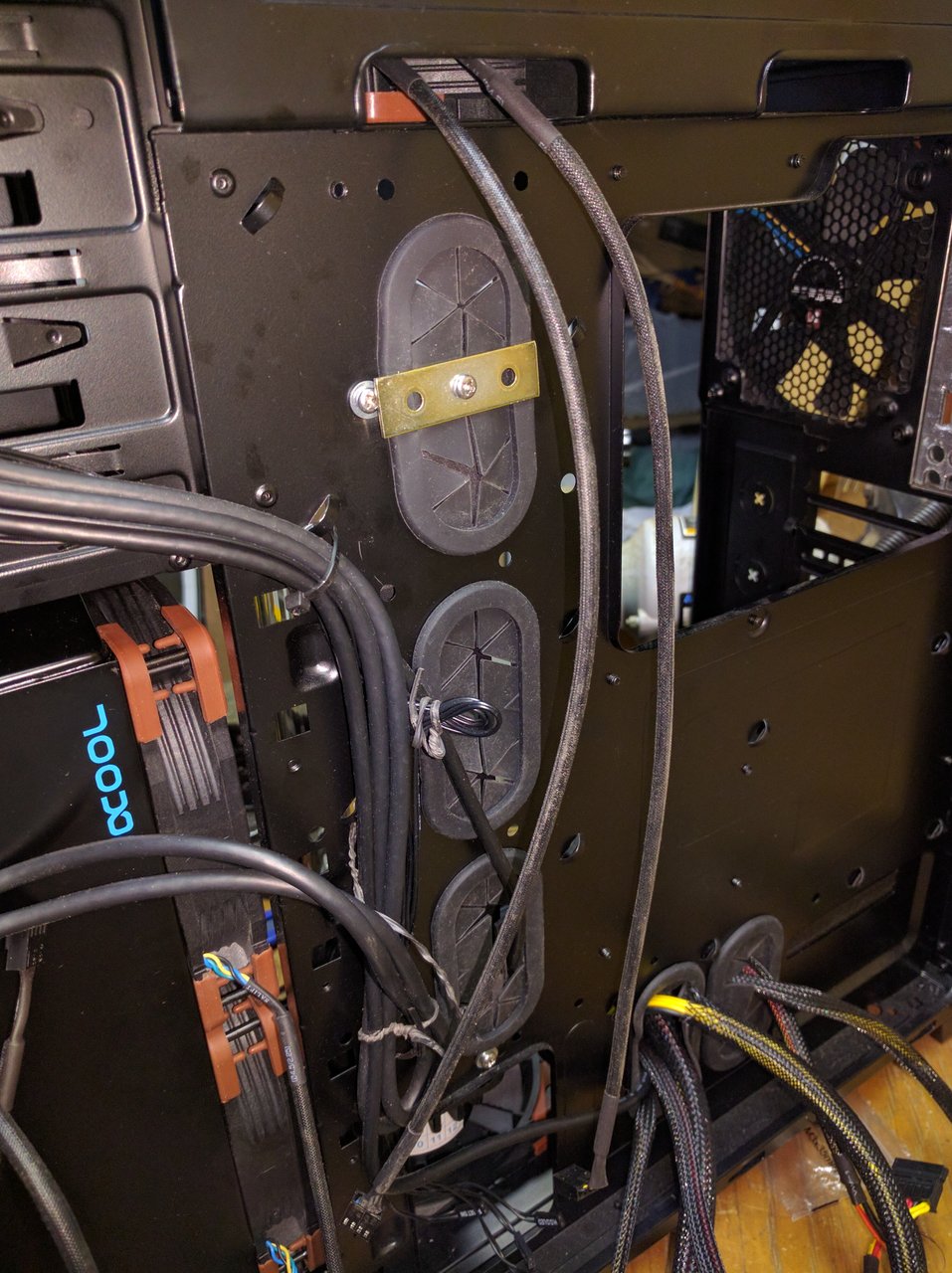
Found something at Home Depot called a "Mending bracket" to help secure the reservoir in place. I drilled a new hole in the center of it so I could screw it in. Now it's no longer attached with only three screws.

IMG_20160816_174723.jpg


Not quite as secure as if it had its own hole, but it appears to be very sturdy.
 
Also,

Turns out I don't have a 4mm hex wrench (needed to get the stock cooler off the New Titan) so having to run to Home Depot... Again...
 
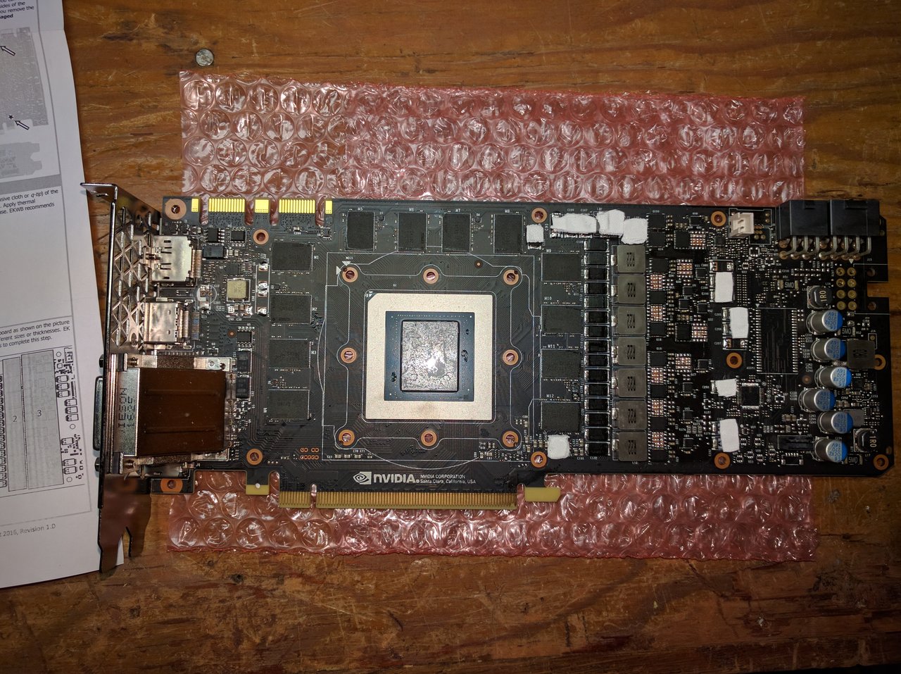
I have to say, the Pascal Titan X is the first video card I have cracked open where the manufacturer didn't use excessive paste.

IMG_20160816_194822.jpg


The instructions that came with my EK water block are incorrect. It says to remove the circled hex screws on the back of the card. ALL screws on the back of the card had to be removed in order for the stock cooler to come off, including the 4 that were not circled.
 
So jelly man.
I want one, but can't justify one yet. 1440p isn't stressing my 980ti @ 1400 yet. First an ultrawide, then some new video bling. This is the first time that I've given good consideration to an ultra enthusiast product, and it's killing me! Itll rot on the 1440p, and if I got that, then no ultrawide. Le sigh
 
Most difficult part of this build this far:

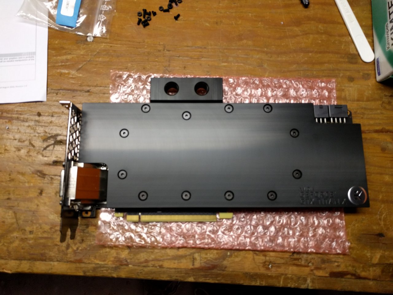
Getting the blue film off of the thermal tape provided with the EK full cover block...
 
Well, I'm not going to get the routing I wanted. I had originally planned on using the return on the top of the res, but I just don't think that is going to work well, so I'm using one of the bottom returns as well, which will involve running a tube from the CPU outlet over the GPU and back to the res.

I'm sure it won't be terrible, but it won't be what I really wanted.

IMG_20160816_223958.jpg


I think I'm done for tonight. Tube cutting and losing fingertip skin to compression fittings tomorrow.

I must have had a brainfart and over-ordered fittings though.

I have three caps, two male to males, two 90 degrees, four 45 degrees and and 10 compression fittings left over... (?????)

I might have forgot I ordered some and ordered the same thing again (oops). What a waste of money...

IMG_20160816_224638.jpg
 
Heck, I decided to give the tubing a go tonight as well.

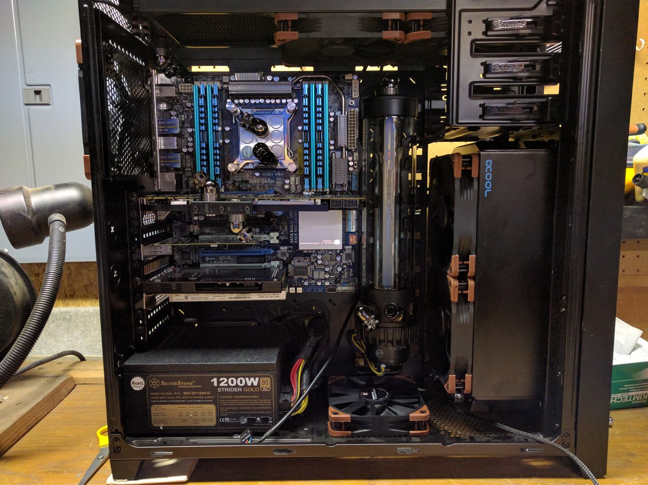
Here is my first pass. I'd appreciate any comments. Is anything too long, too short or a bad idea? I have plenty of tubing left so I can re route if anyone has ideas for improvement!

IMG_20160816_231430.jpg


And yes I know, picture quality is crap.

I'll be doing vanity shots with the SLR when it is all done :p
 
Last edited:
Looks good man! Fill 'er up :)

Question- Did you rotate the cpu block on purpose? They're supposed to be installed a particular way, unless HEDT is different from desktop.
 
Heck, I decided to give the tubing a go tonight as well.

Here is my first pass. I'd appreciate any comments. Is anything too long, too short or a bad idea? I have plenty of tubing left so I can re route if anyone has ideas for improvement!

View attachment 6784

And yes I know, picture quality is crap.

I'll be doing vanity shots with the SLR when it is all done :p

That looks fine to me. My only suggestion is to make the tubes connecting to the jackets a little longer, so you've got some slack in case you need to pull the the CPU or graphics card out. As it is, it looks like you'd be committed to draining the coolant if you needed to do that.

I might also consider reversing the fans on that front radiator, so they draw air into the case. Are you not going to put a third fan on the top rad?
 
Looks good man! Fill 'er up :)

Question- Did you rotate the cpu block on purpose? They're supposed to be installed a particular way, unless HEDT is different from desktop.


Hmm. My ins and outs are in the right location (in comes from the top rad goes into the block in the hole closest to the center, and out to the res in the hole closest to the bottom)

As far as horizontal vs vertical hole alignment goes, I read a few year old analysis on I believe the Xtremesystems forums where a user tested all the common blocks at the time in both regular horizontal orientation and "goofy" vertical orientation. They found that for non-E chips the regular hoizontal orientation performed the best, but that for -E chips like mine, the goofy vertical orientation performed the best.

I can't seem to find the data now, but when I do dig it up, I'll link it here.


EK has that information in the booklet that came with the block. This is important with EK blocks due to the jet plates
 
That looks fine to me. My only suggestion is to make the tubes connecting to the jackets a little longer, so you've got some slack in case you need to pull the the CPU or graphics card out. As it is, it looks like you'd be committed to draining the coolant if you needed to do that.

For now, yeah. Next iteration I may put a couple of QDC's in there, one on either side of the GPU, in order to make my life easier, but that's not in the cards this time around.

I will have to install the backplate on the GPU when it arrives, but I think I can do that without removing the GPU from it's position. Other than that I don't think I'll have any reason to take it out!

I might also consider reversing the fans on that front radiator, so they draw air into the case. Are you not going to put a third fan on the top rad?

So yes, once I am done with the tubing, I am going to put a fan in the top. The fan just isn't there because with my Sasquatch sized hands I can't tighten the compression fittings with it in place. I'm also going to have to Dremel the side of the fan a little bit, just to give the 45 degree fitting a little clearance. I could force it in right now, but I don't want to force pressure on the fitting, as that seems like a bad idea from a leak perspective.


As far as airflow goes, I have gone with a slightly unorthodox flow for my build.

I have reversed the direction of the rear fan to pull air in. I also use the bottom fan to pull air in.

All other fans push out through the radiators.

I know that pushing air in through radiators is the more orthodox approach in the water cooling community, but I think this will work for me.

I do wind up with slight negative pressure, which I try to address by having the rear and bottom fans push in, but I still have more fans blowing out than blowing in, so it will be negative.


I didn't want the warm air from one radiator blowing through the other radiator, so I decided that both radiators had to have airflow in the same direction (either in or out), and I didn't want to push hot air which tends to want to go up, in the opposite direction down through the top radiator so I decided on this airflow.

I think this should be fine though, because the typical arguments for positive pressure are as follows:

1.) "Air is cooler outside the case, so you'll get better performance if you pull cool air from the outside through your radiator."

This is typically true, but I have water blocks on my hottest components blowing all the heat outside and have decent airflow, so the air inside the case shouldn't really be much warmer than the air outside the case.

2.) "It's easier to control dust when you control where the air enters the case, because you can put a filter there. In a negative pressure system, air enters wherever there is a crack or crevice, so you can't control dust."

This is true, but I have been running this way for a year with two Corsair H90's (one connected to each of my 980ti's) blowing out the front, and my Corsair H110i GTX glowing out the top, and I haven't had a dust problem. While my case looks dusty under flash photography in some of the pictures above, in person you can't see if, even if running a finger through it. Maybe I just have a clean house?

Either way, if there is some really compelling evidence that I am wrong, and intake is definitely the way to go, I might switch things around, but it would involve taking the front radiator out to rotate the fans, and that would involve taking the reservoir out to reach everything, so I'm not sure I want to at this point :p
 
Last edited:
EK has that information in the booklet that came with the block. This is important with EK blocks due to the jet plates

This is all that comes in the box.

It speaks to which plates and inserts to use with each CPU, as well as which mounting hardware, but it does not address orientation.
 
There is also something to be said for 'whatever floats your boat'. My ongoing loop-o-teardown and play had been normal and goofy a few times, seems to have so little difference it's hard to separate that from mounting / thermal paste randomness. As far as the airflow- if you have negative pressure you will need to clean out the case a little more, but that's not really a big deal as long as you can get to it.
 
This is all that comes in the box.

It speaks to which plates and inserts to use with each CPU, as well as which mounting hardware, but it does not address orientation.

Ill check my manual for my Evo MX when I get home. I read about it in that one for sure
 
Ill check my manual for my Evo MX when I get home. I read about it in that one for sure

So, the testing I was referring to was by Xtremesystems forums user Moonman. He may just be a forum user, but his tests are well regarded and rigorous.

Unfortunately his charts and images have mostly expired as it is an older forum post, so I had to resort to the Internet Archive to read some of it.

Link Here (Be patient, images load slowly)

So as mentioned, for coolers with channels in them, the optimal orientation appears to be the opposite on non -E CPU's and on -E CPU's for some reason. Now in his testing he lists the optimal orientation with Sandy-E the inlet on the bottom and outlet on the top. I installed it with the inlet on the top and the outlet on the bottom. I hope this doesn't make a big difference, but since I have an Indigo Extreme TIM sheet under there, I can't take it back off and put it back on without wrecking it, so I am going to go with it as it is for now, and hope for the best.

I'm not too concerned. I was able to hit 4.8Ghz (even 5.0 Ghz on cold days) with my 3930k and sealed water coolers, so this should be enough either way. Where I am the most interested in max cooling performance is on the GPU. I want to get every last drop of performance out of it. My 4k screen demands it!
 
Ahh, thats what I thought. I did feel I remembered goofy for the E's, due to die orientation.
How you like that sheet? I wanna replace the Gelid I'm using under and over the lid, but havent decided if I wanna go back to the CLU or try something else.
 
Ahh, thats what I thought. I did feel I remembered goofy for the E's, due to die orientation.
How you like that sheet? I wanna replace the Gelid I'm using under and over the lid, but havent decided if I wanna go back to the CLU or try something else.

I haven't deflowered it yet in my current setup, but I used it once before when I had the rare 180mm maingear cooler in my system, and as I recall the temps were much better with the indigo Extreme than with AS5.

The main benefit seems to be that while complicated to install, it minimizes the importance of getting a good mount. You might get equivalent or better performance from some other pastes if you have an absolutely dead on perfect mount, but the indigo extreme seems to take the mount more or less out of the equation, as long as you follow their directions precisely. (you have to reflow it in a horizontal orientation, and follow their detailed instructions for what to look for on the temp chart. If you don't it won't work right.

For my GPU I didn't use the included EK paste, and instead went with the Thermal Grizzly Kryonaut paste as it reviews the best out of all the non-conductive pastes.
 
Back
Top