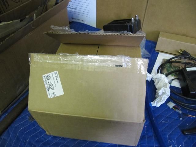
Hello. Its been a moment due to the Easter holiday and waiting on welding brackets. Than I thought I lost my camera until I found it:wallbash::clap:. Update time
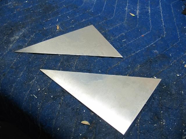
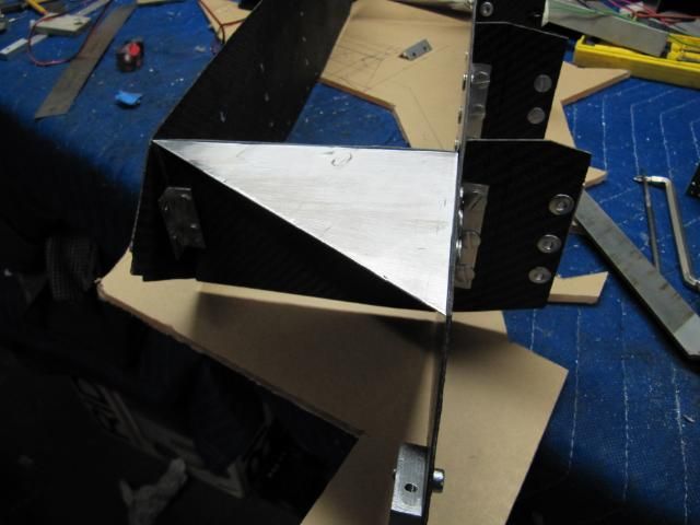
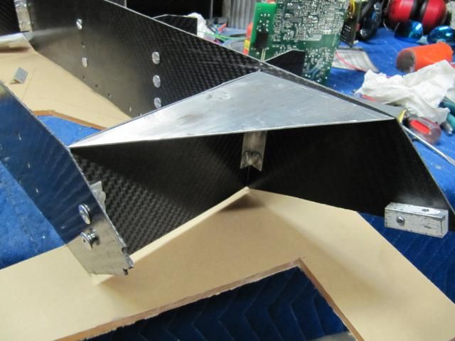
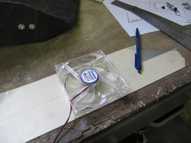
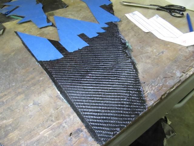
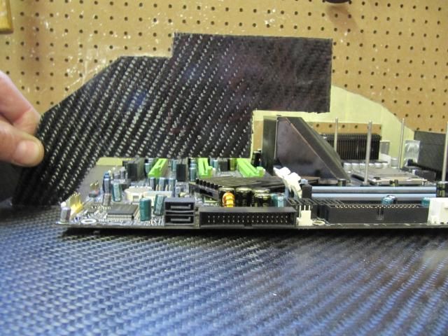
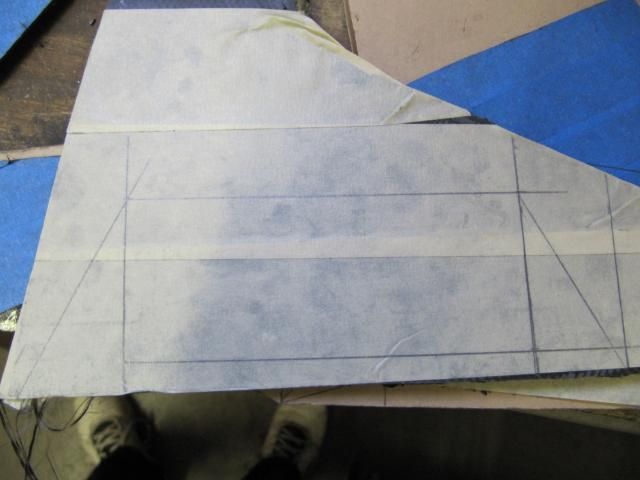
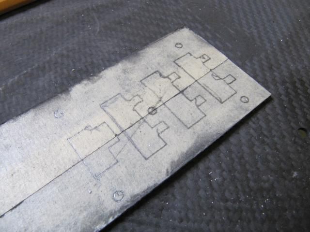
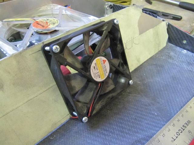
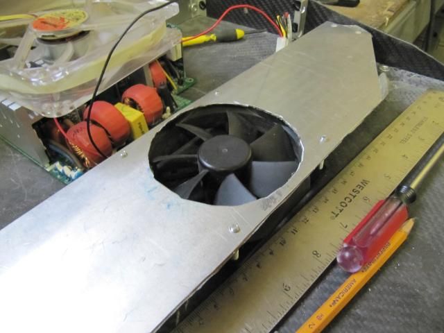
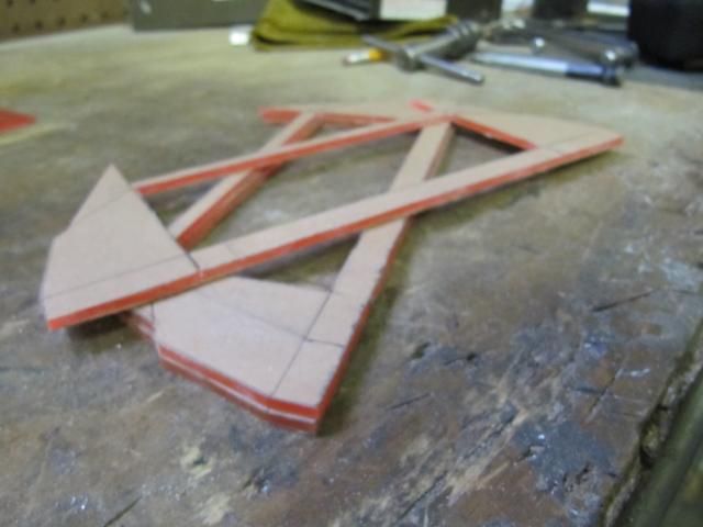
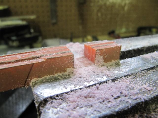
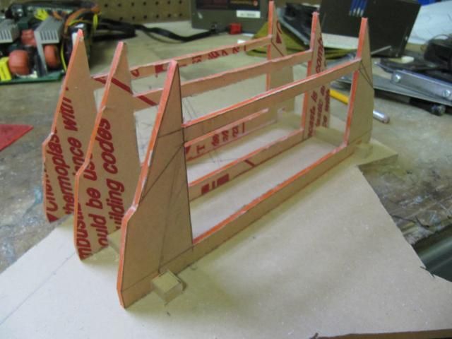
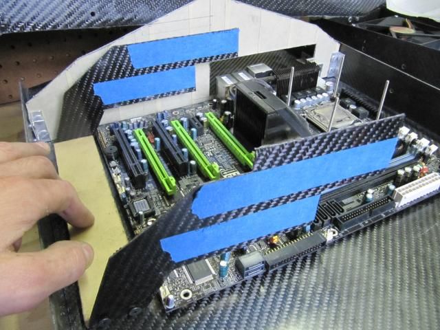
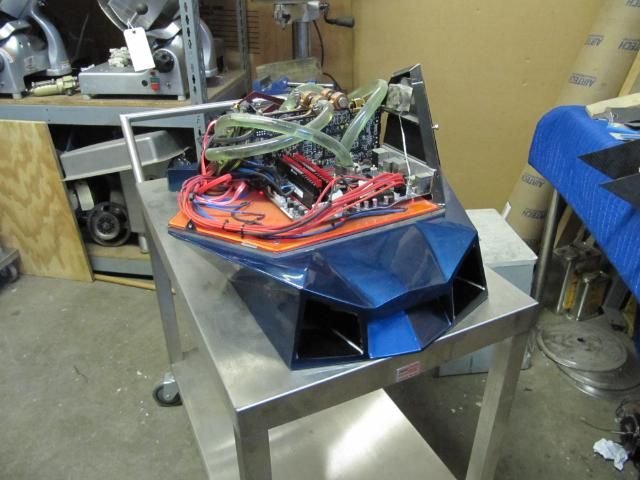
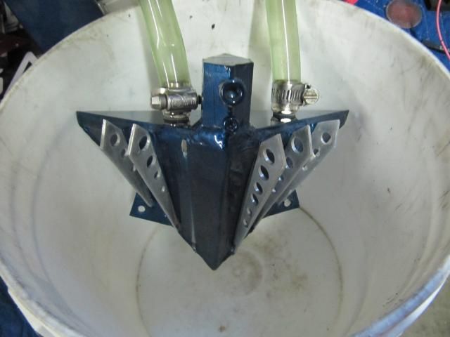
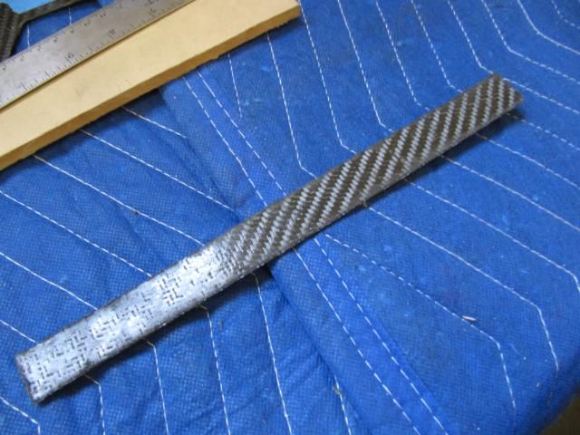
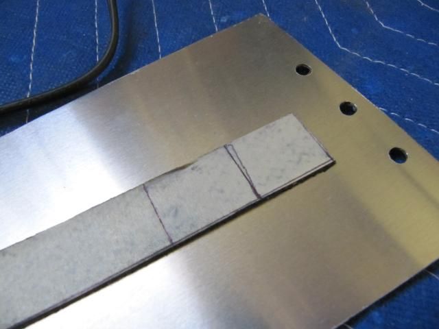
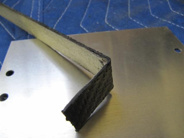
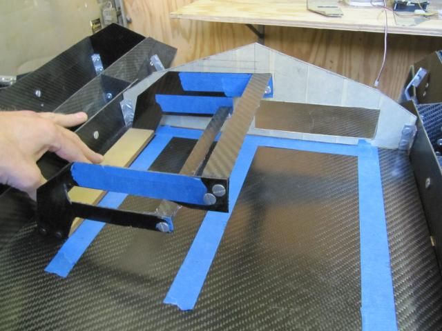
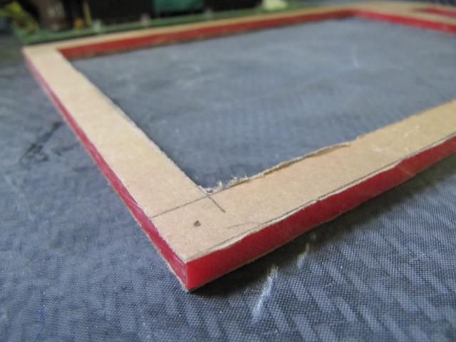
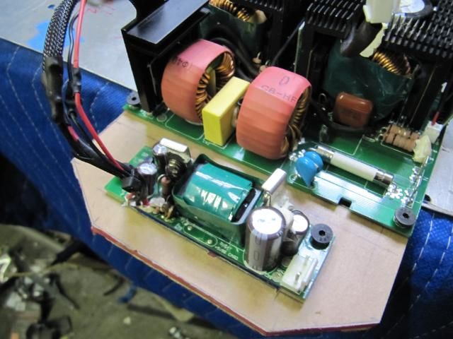
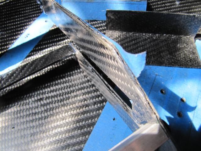
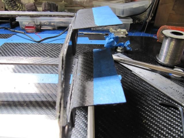
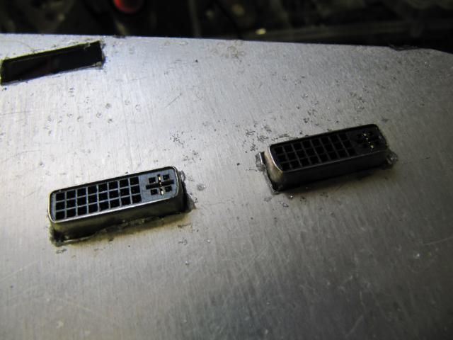
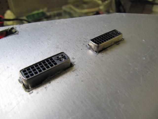
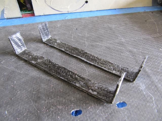
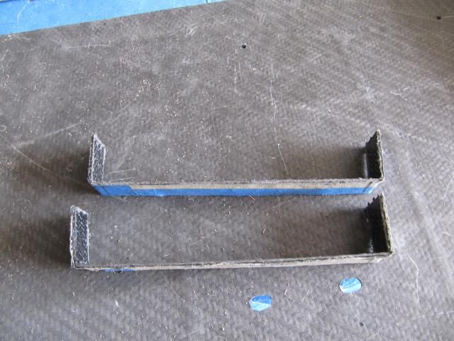
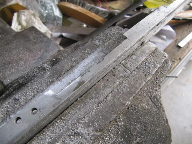
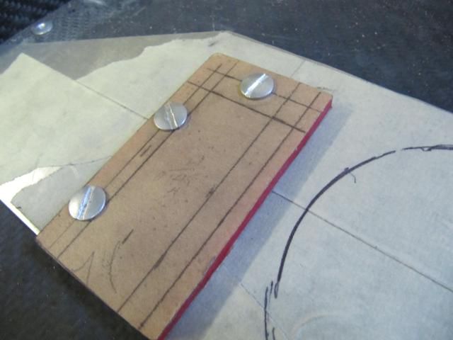
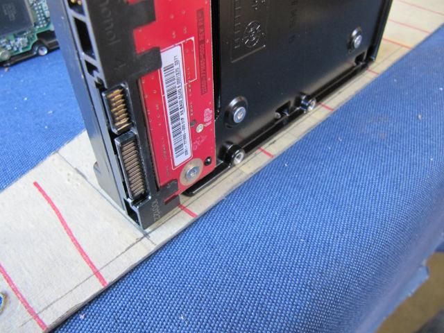
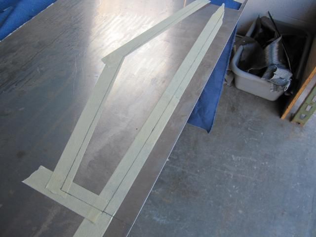
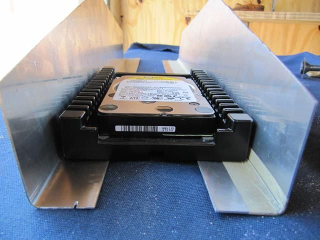
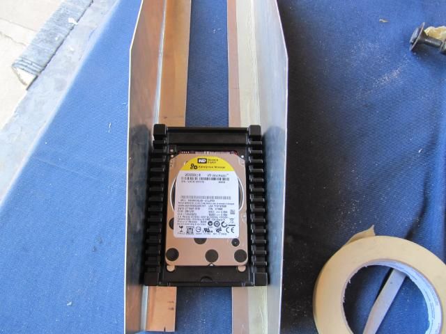
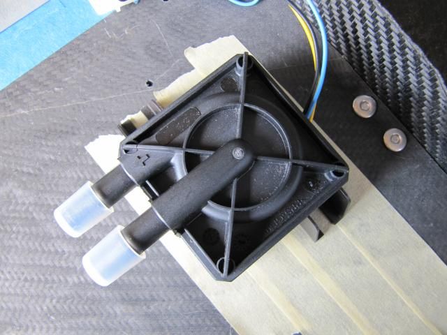
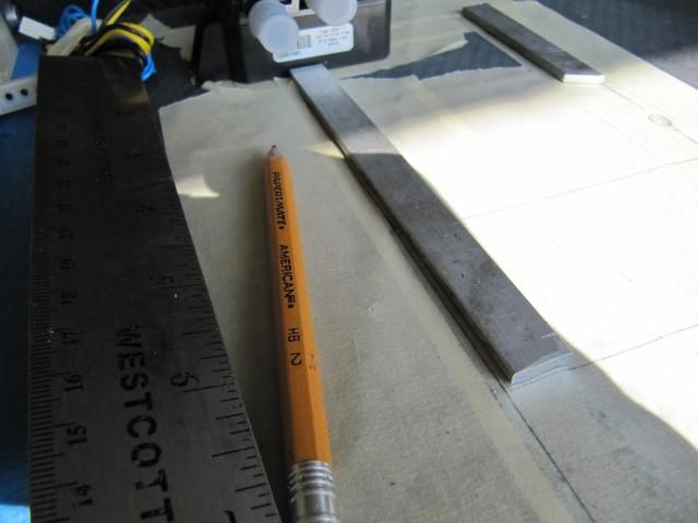
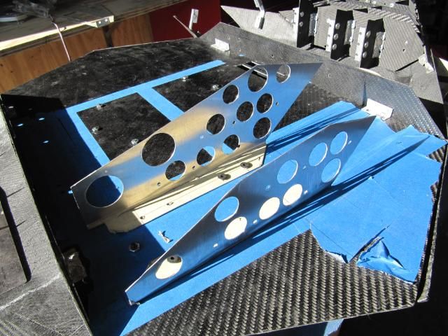
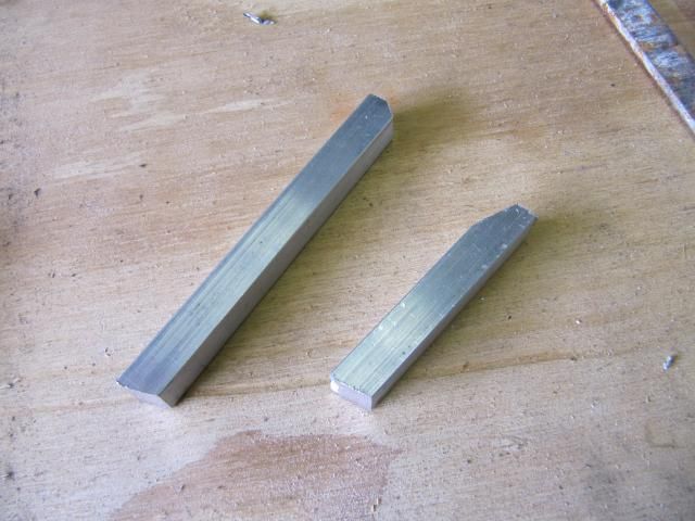
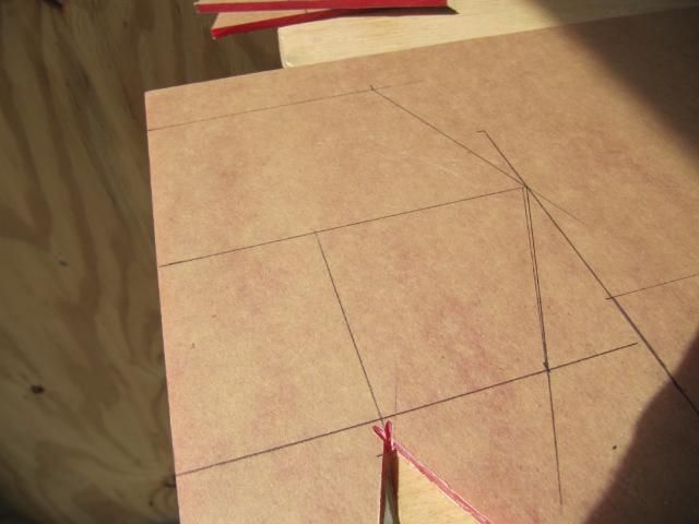
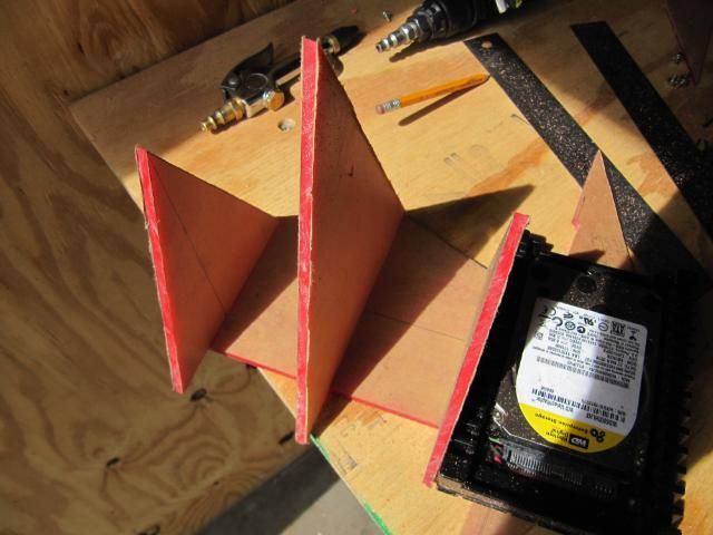
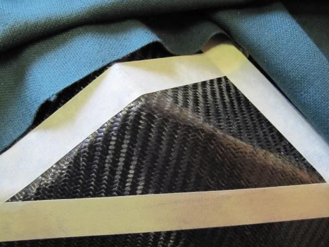
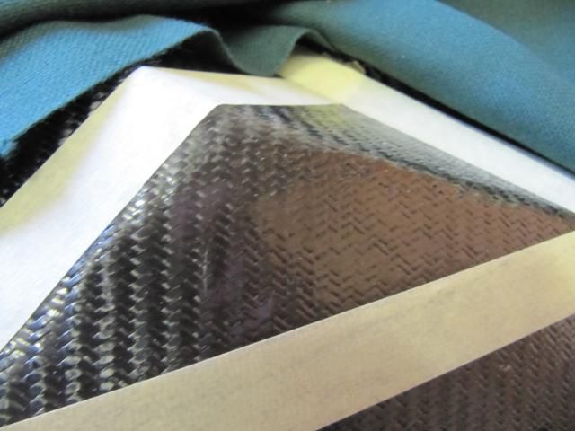
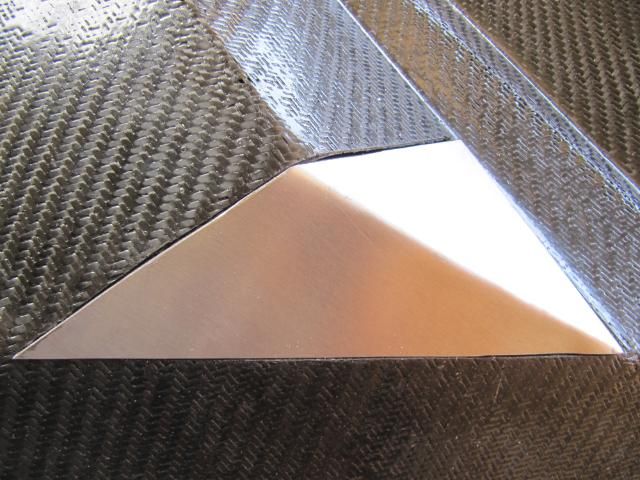
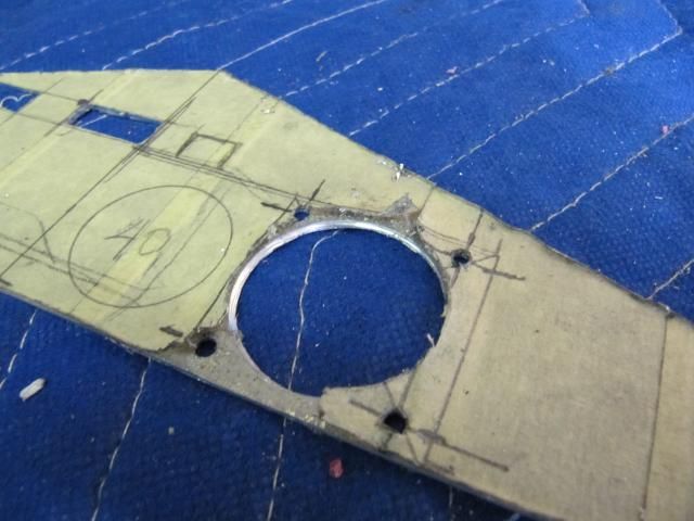
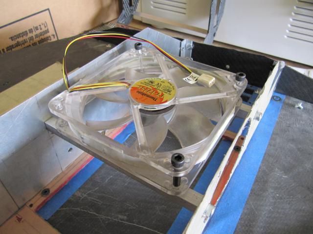
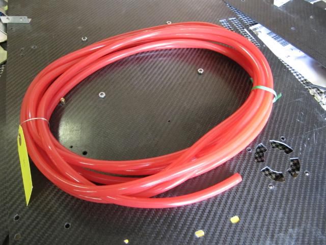
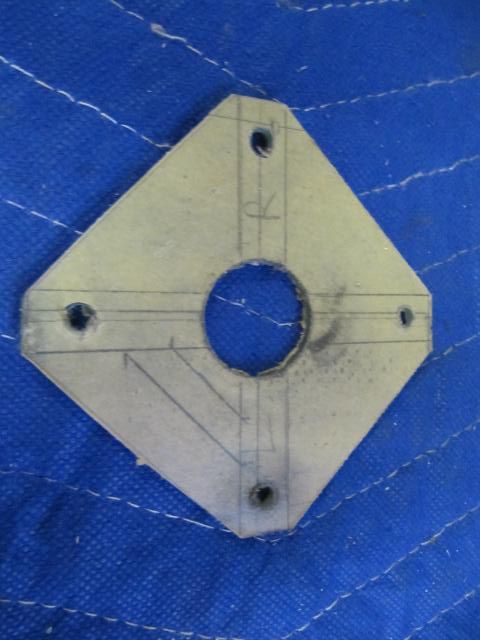
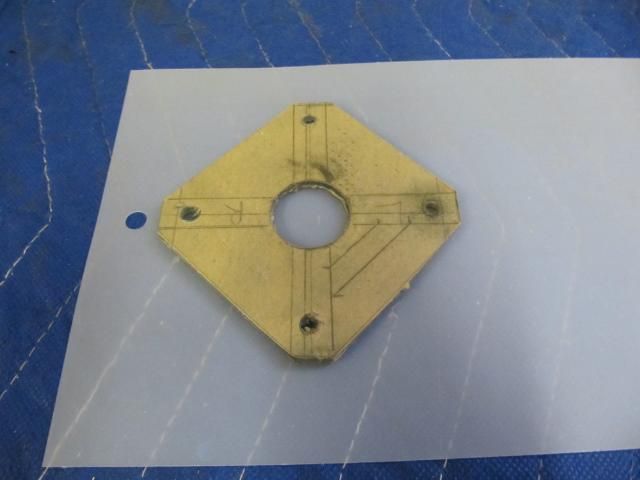
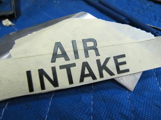
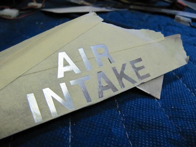
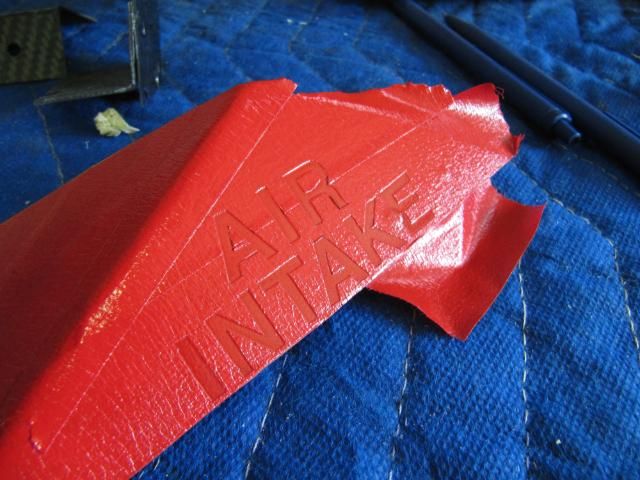
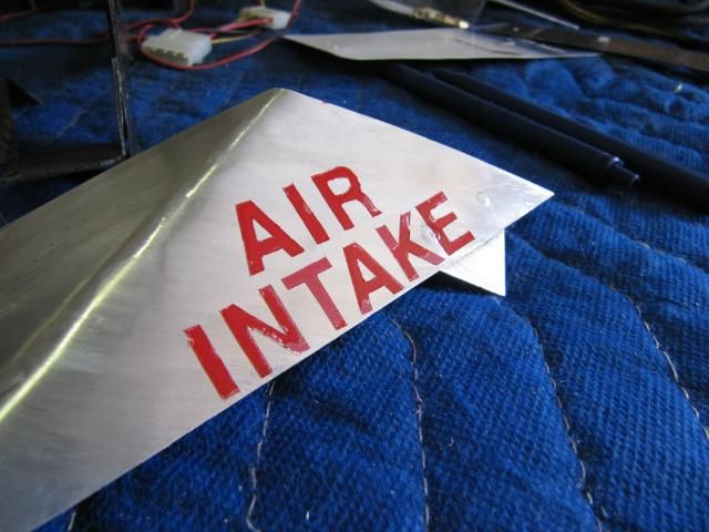
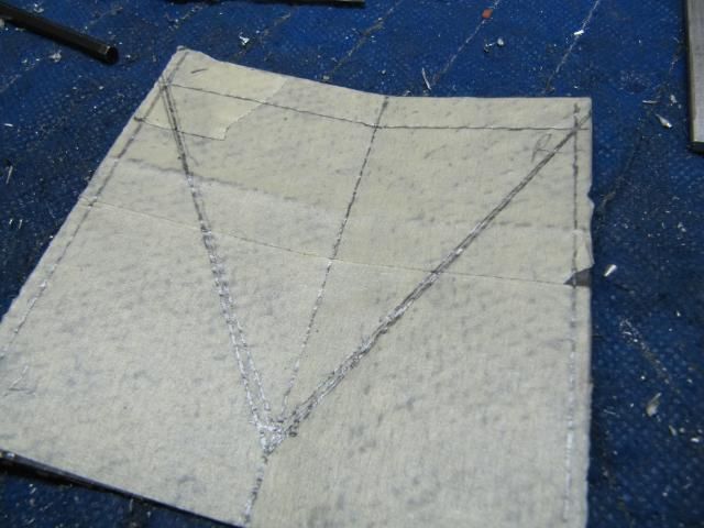
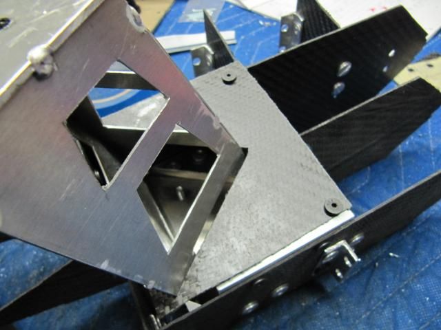
These pieces will be for the intake inlet. They will mount to the frame.
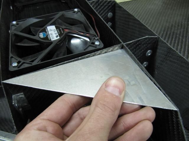
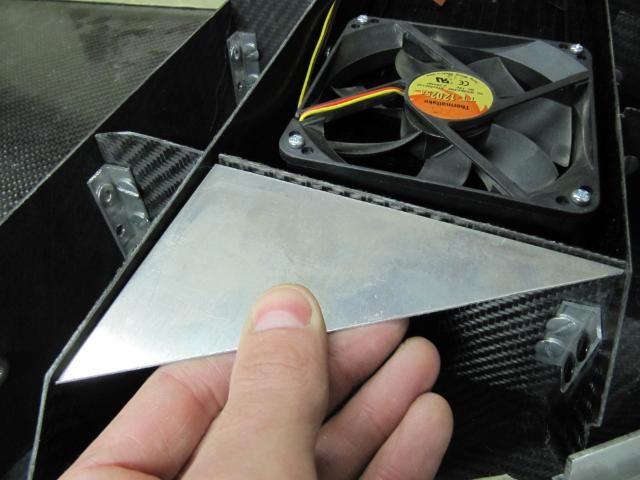
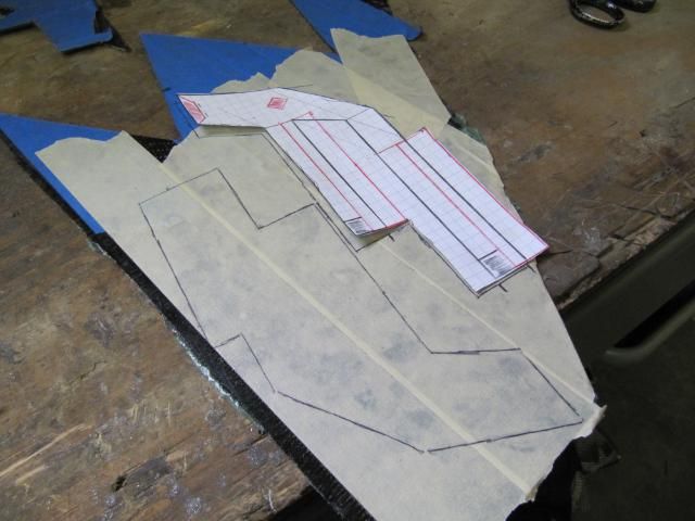
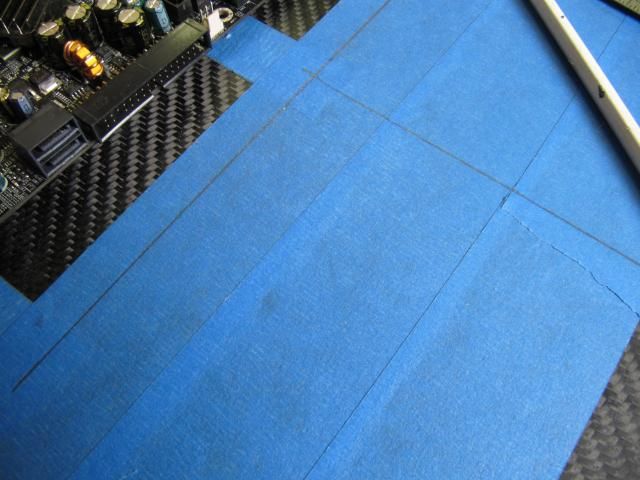
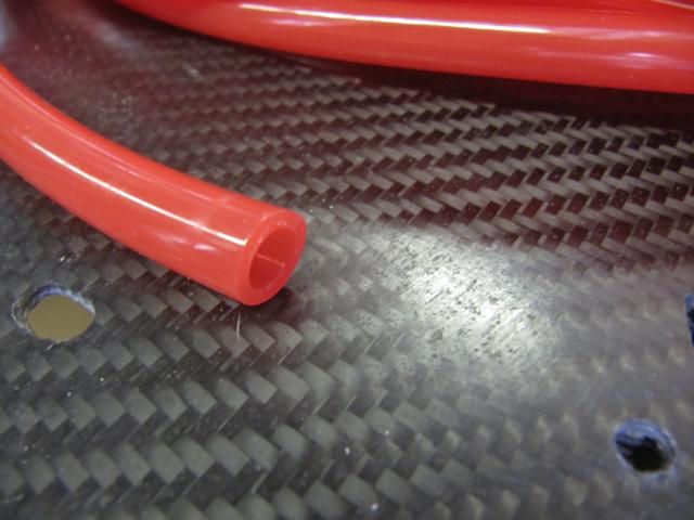
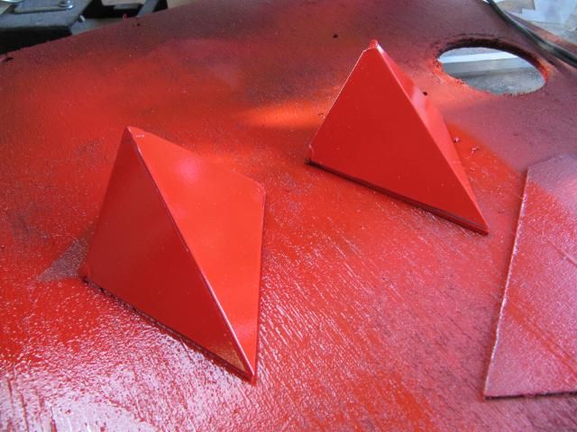
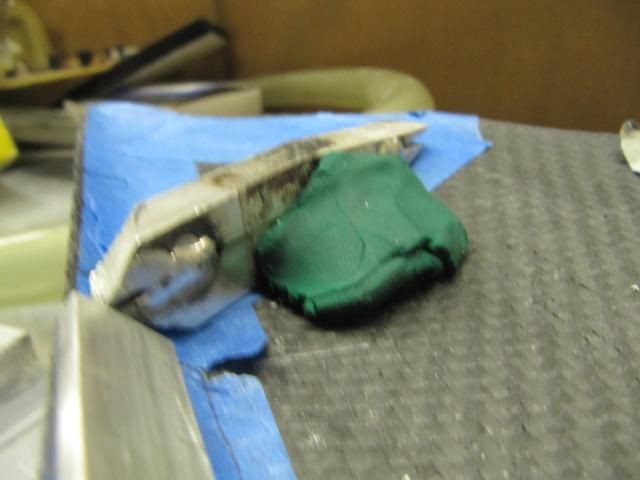
There locations
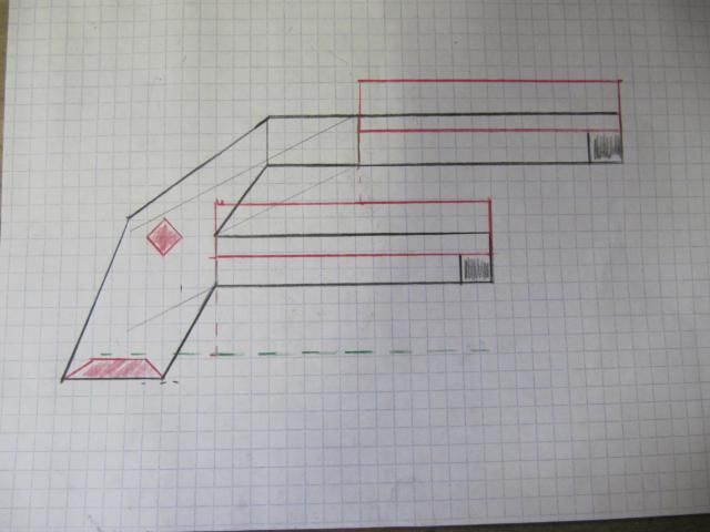
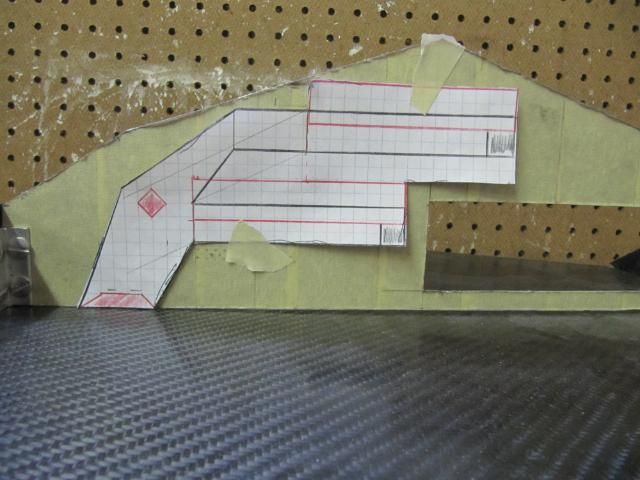
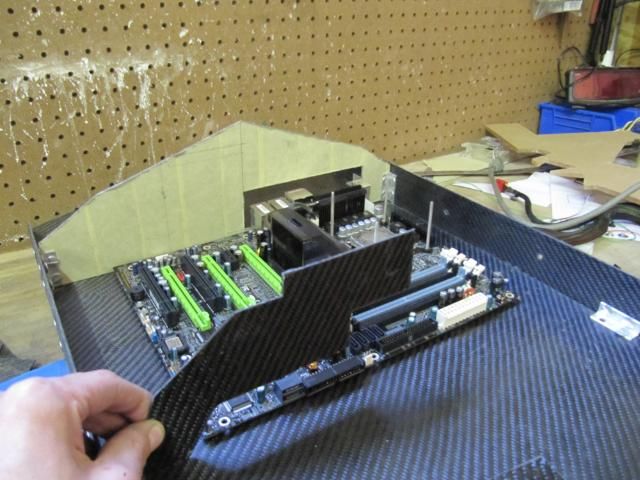
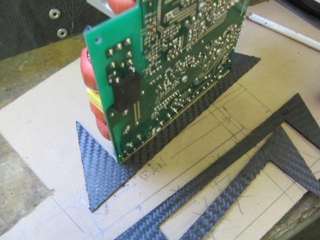
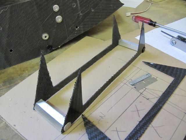
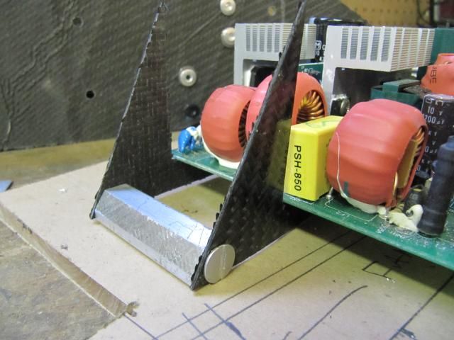
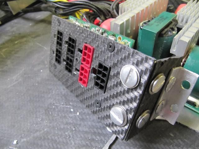
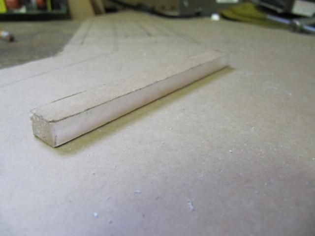
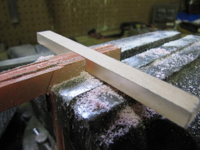
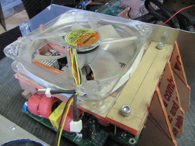
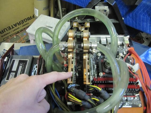
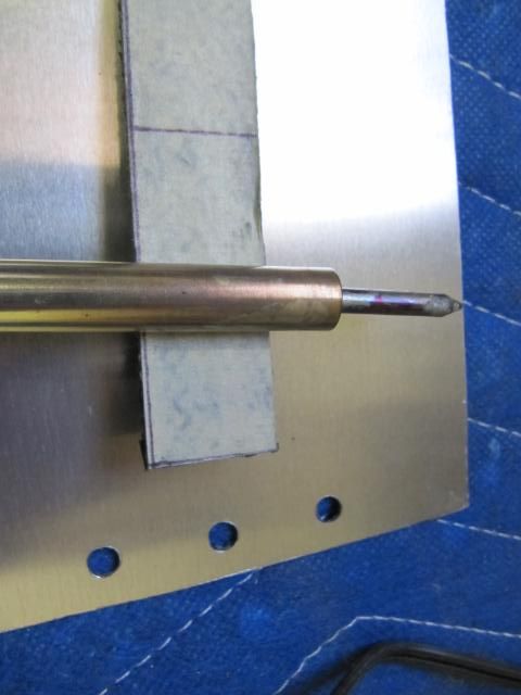
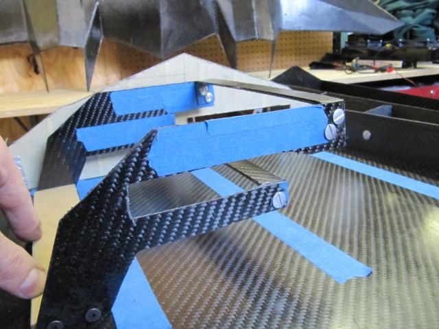
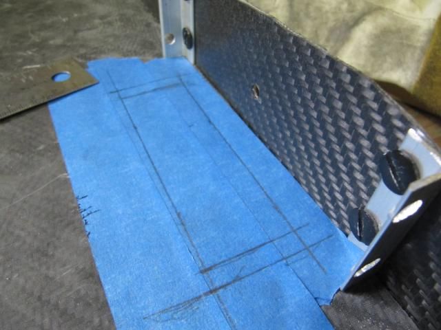
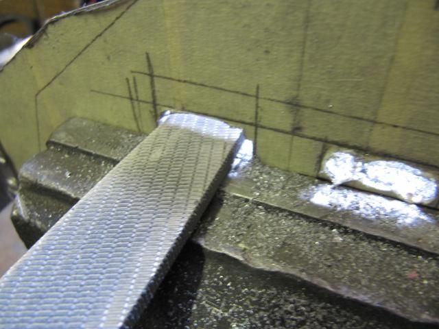
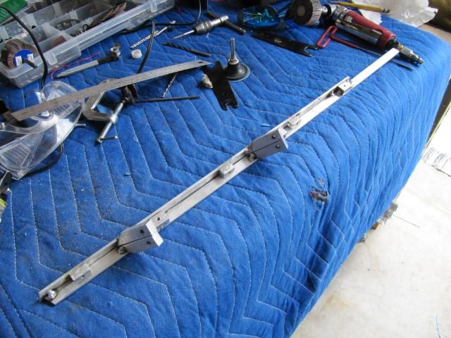
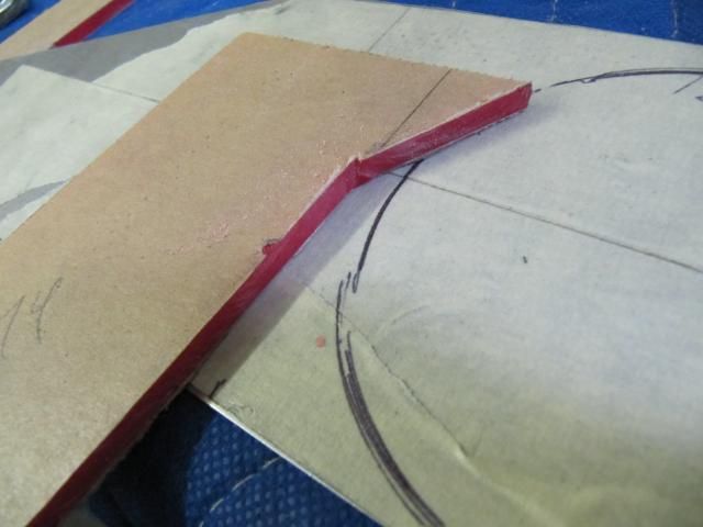
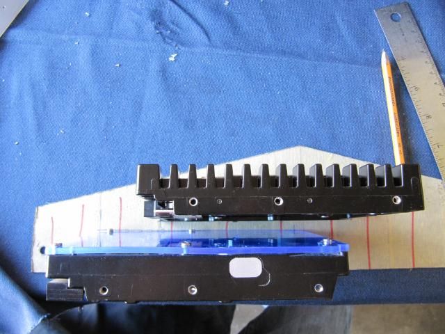
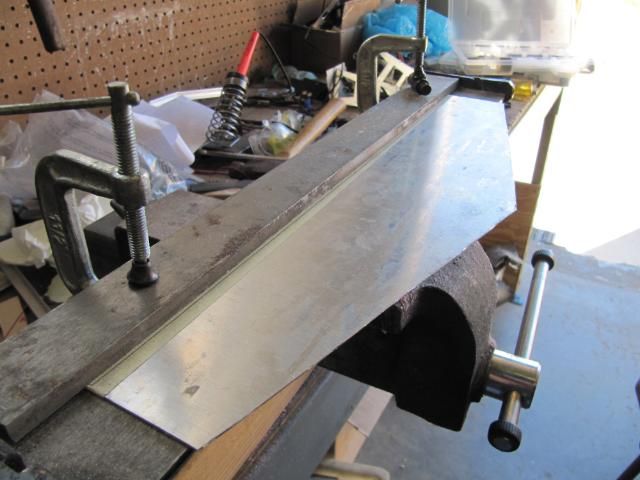
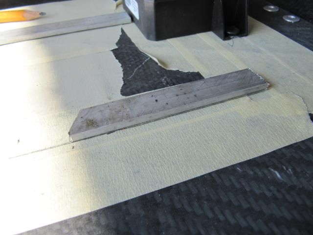
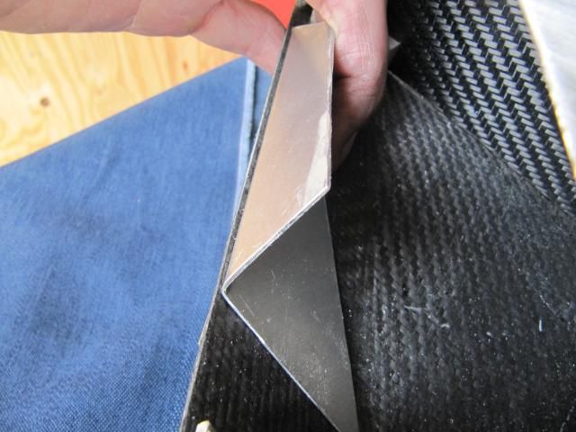
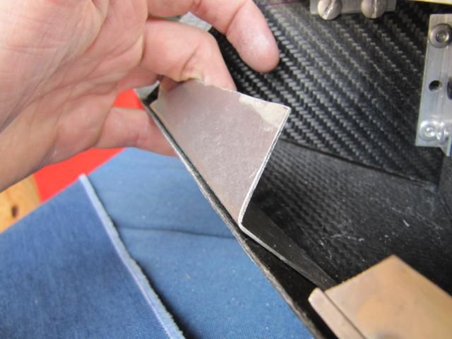
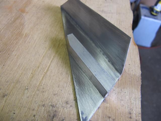
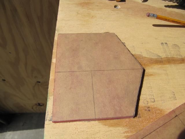
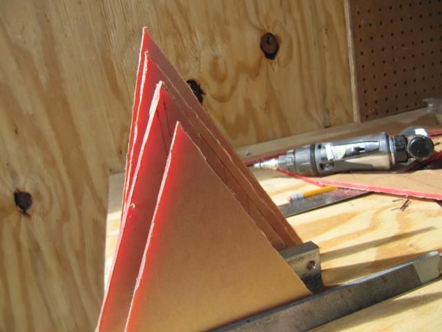
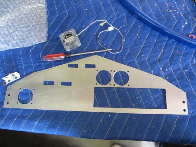
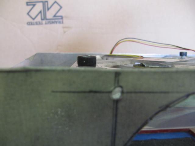
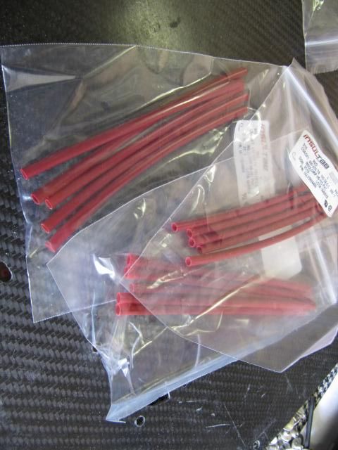
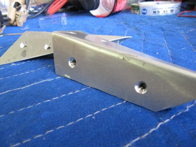
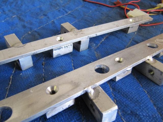
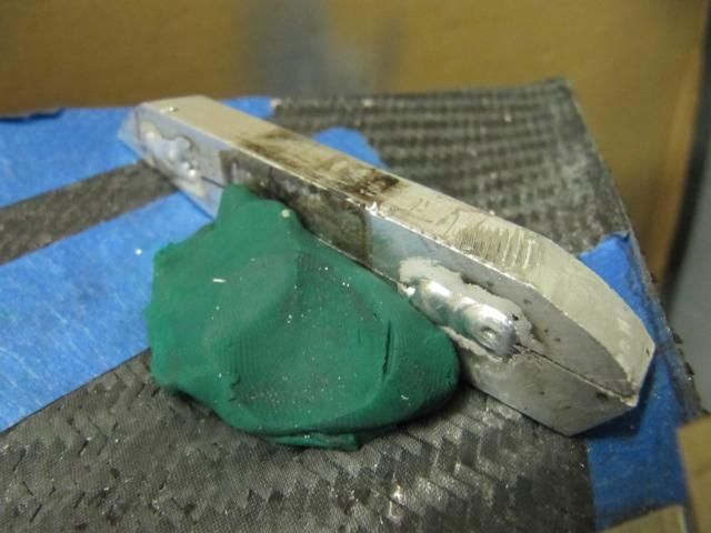
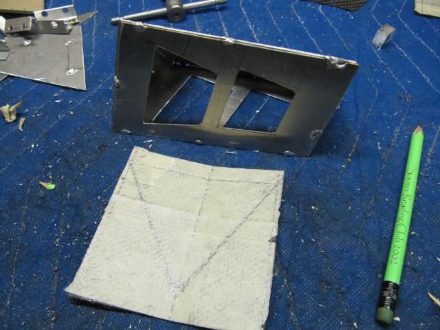
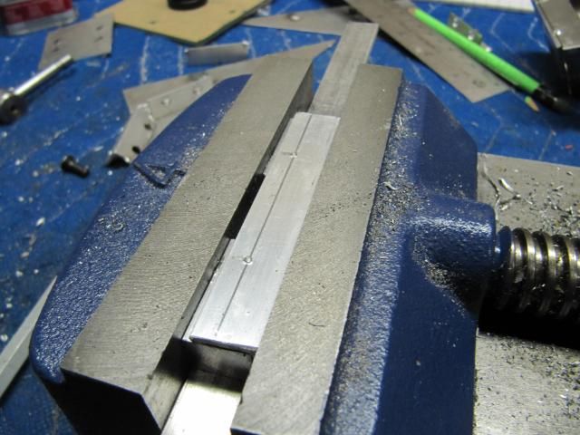
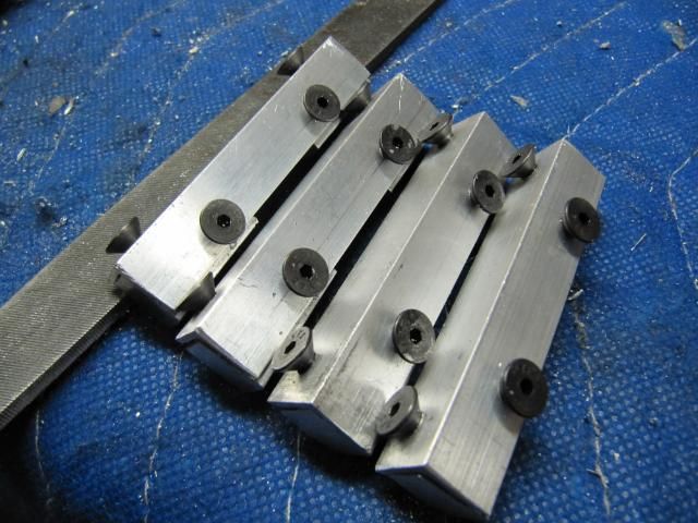
The bracketing that I decided to roll with is simple and lightweight.
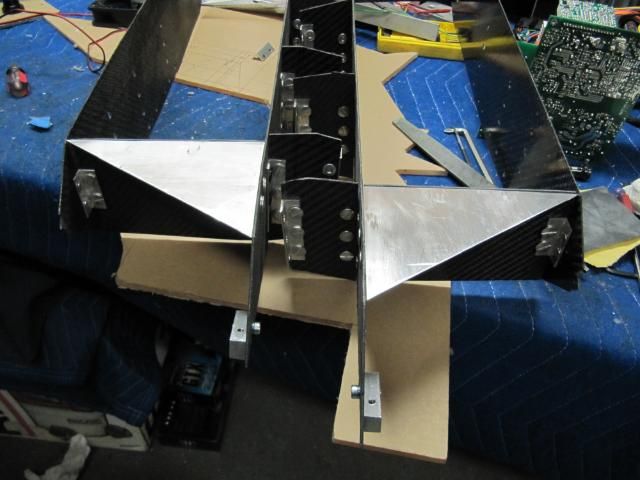
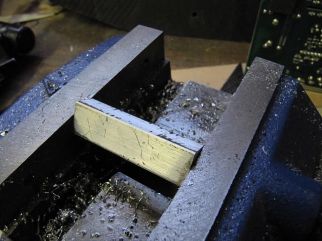
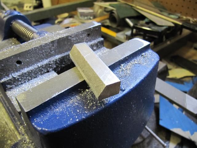
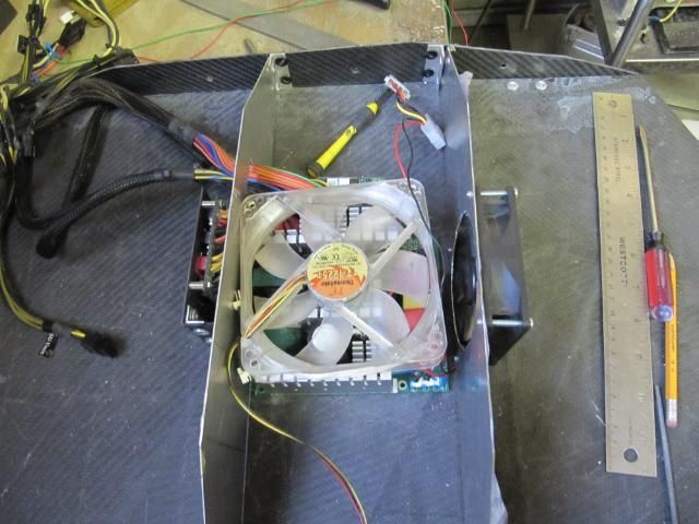
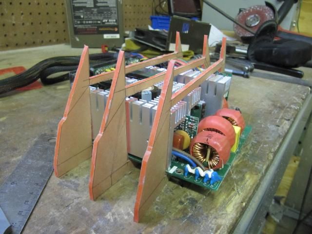
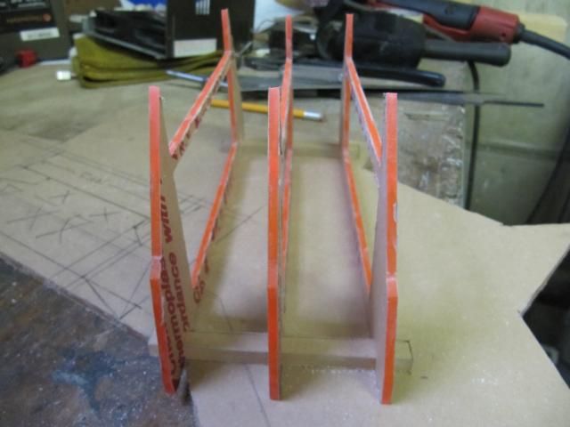
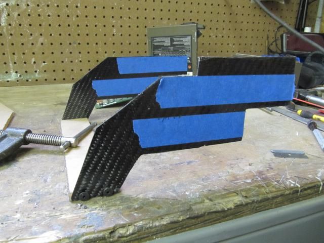
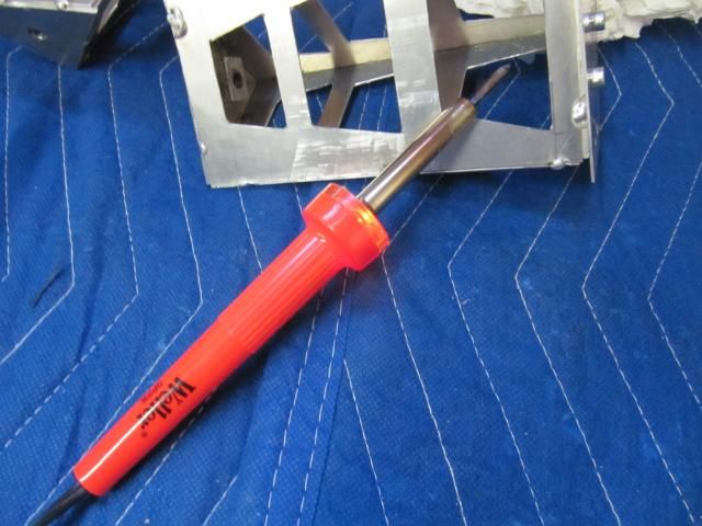
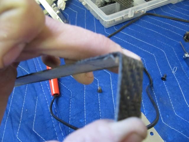
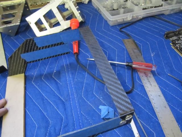
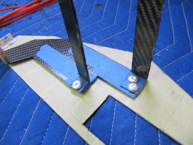
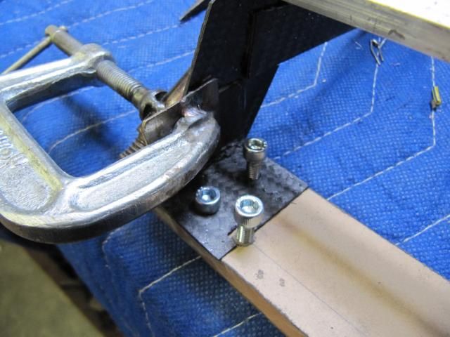
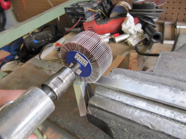
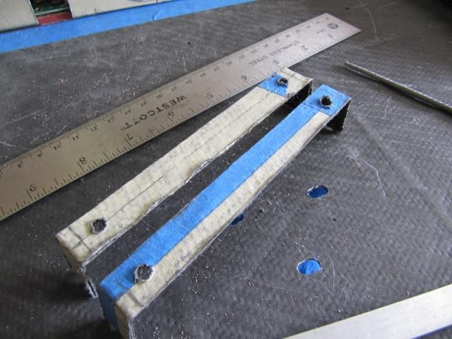
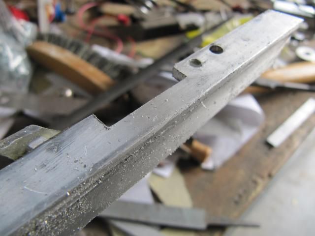
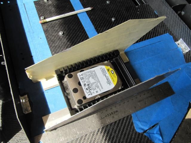
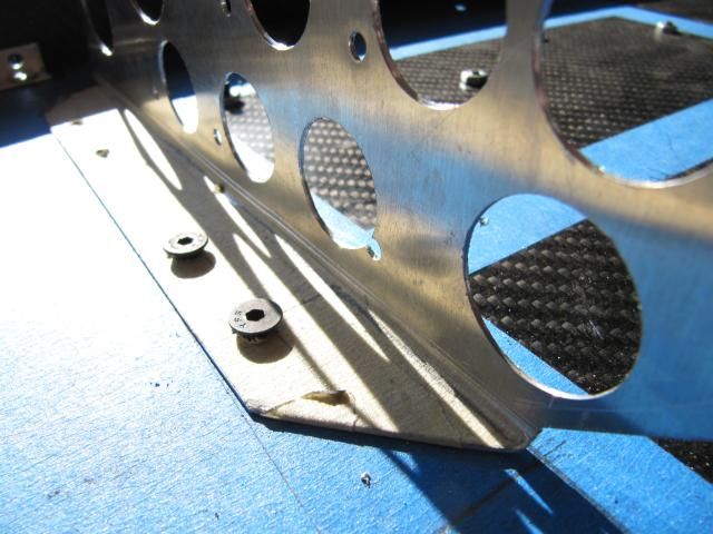
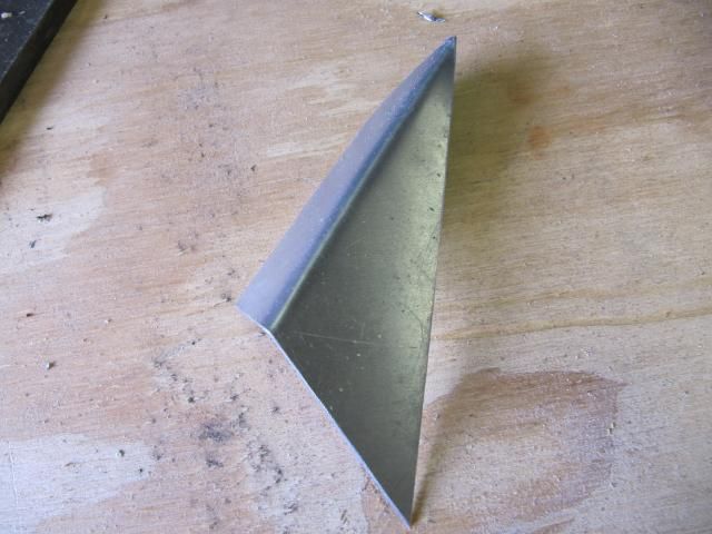
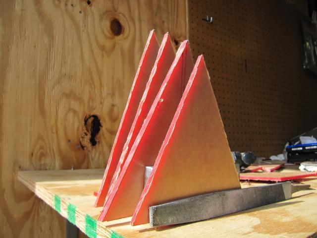
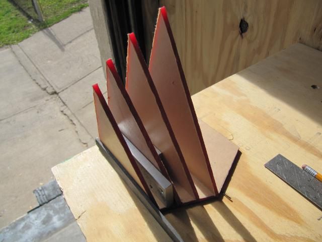
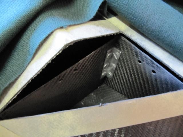
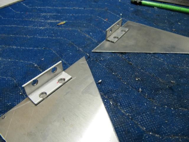
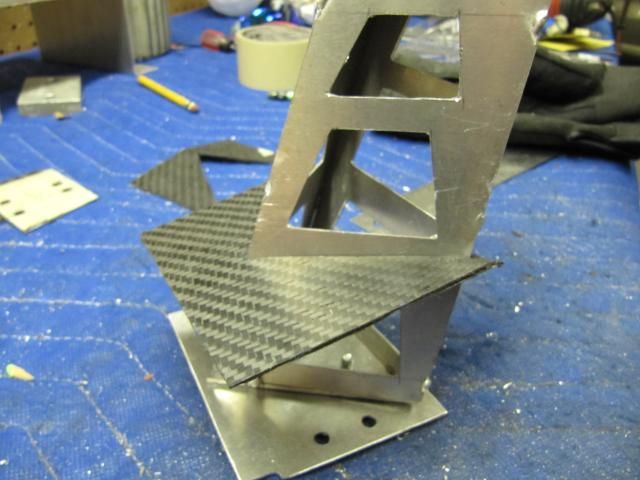
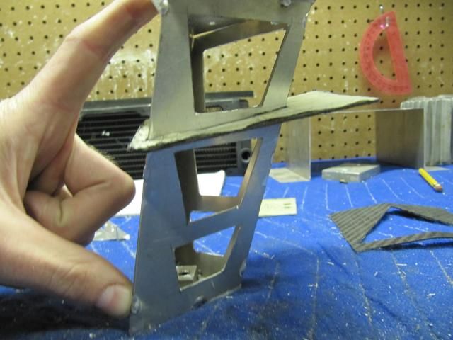
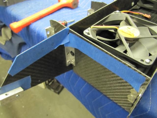
Moving onto finishing the wing-tip brackets
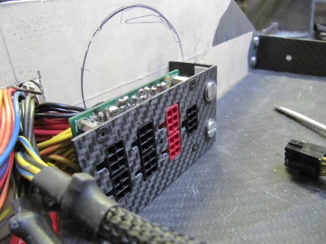
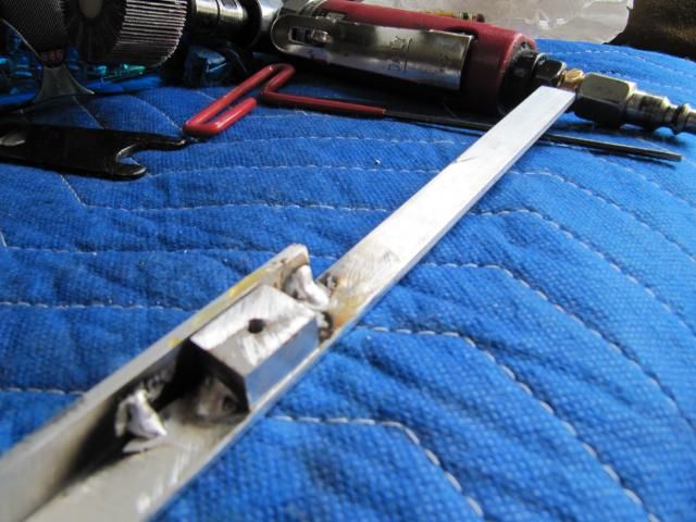
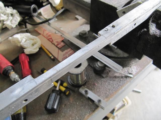
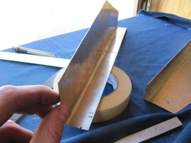
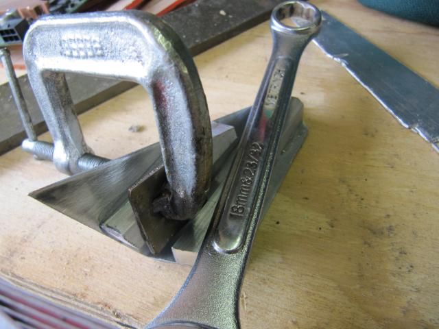
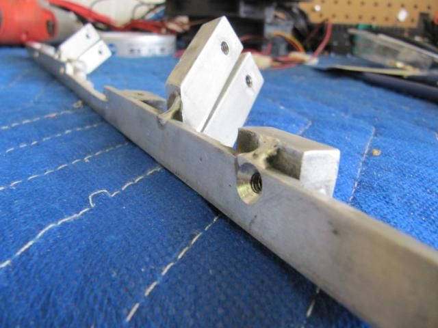
So I had to wait the weekend out before I could due get these mounted properly. They need to be welded together. Trying to mount each piece than weld would most likely result in some major misalignment of the covers.
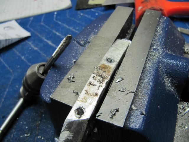
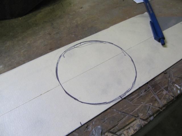
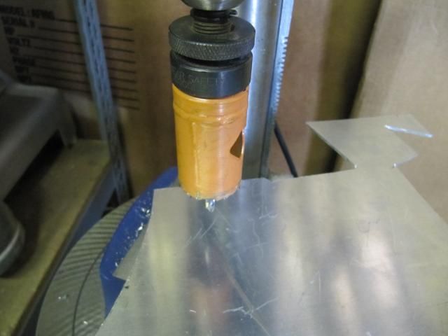
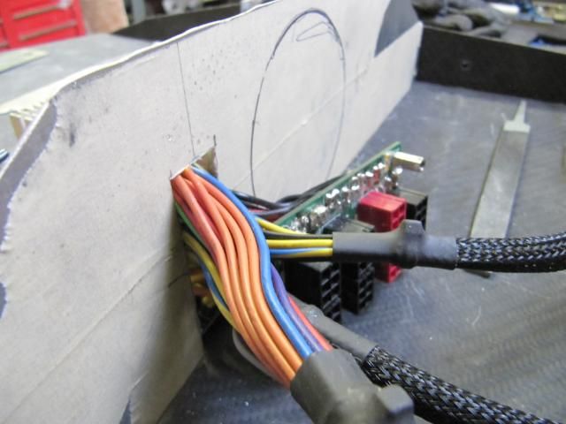
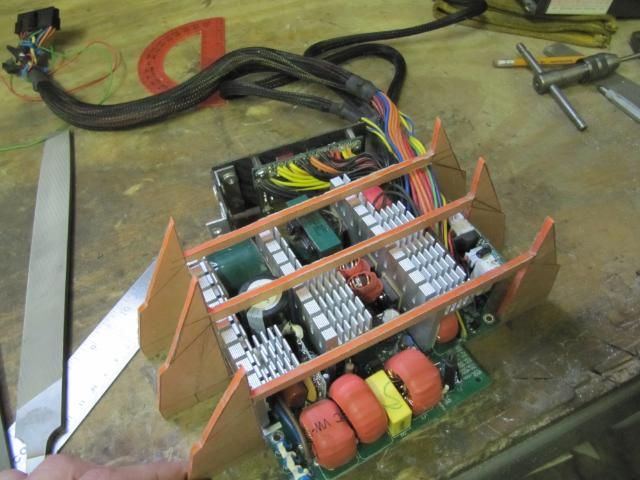
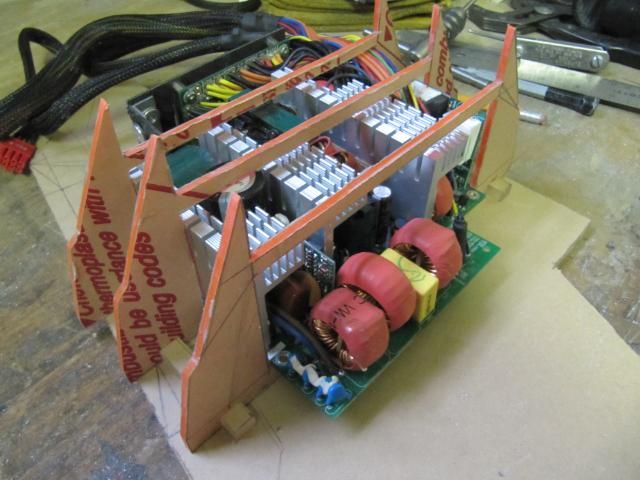
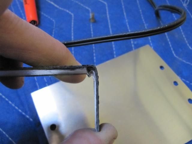
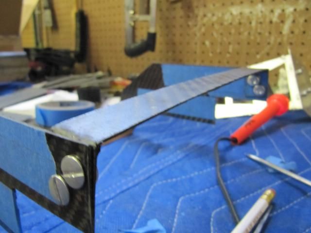
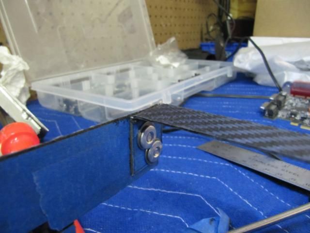
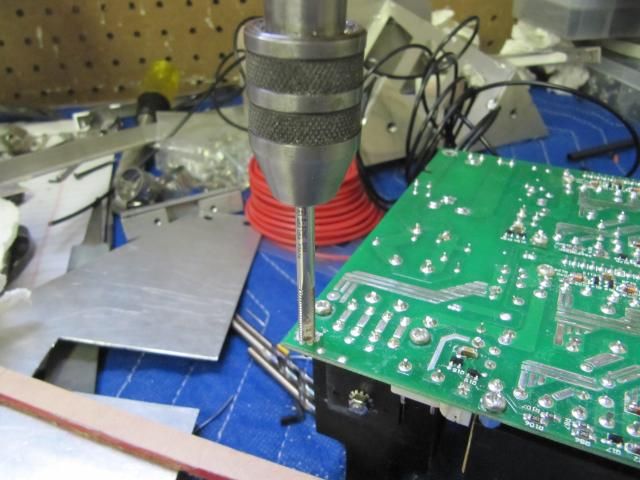
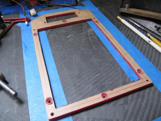
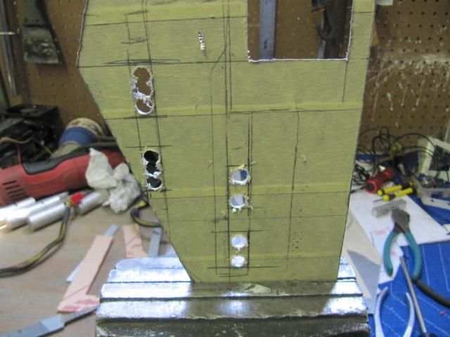
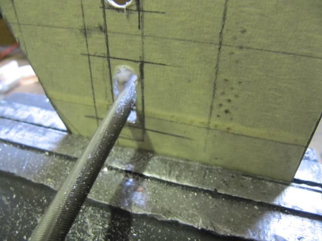
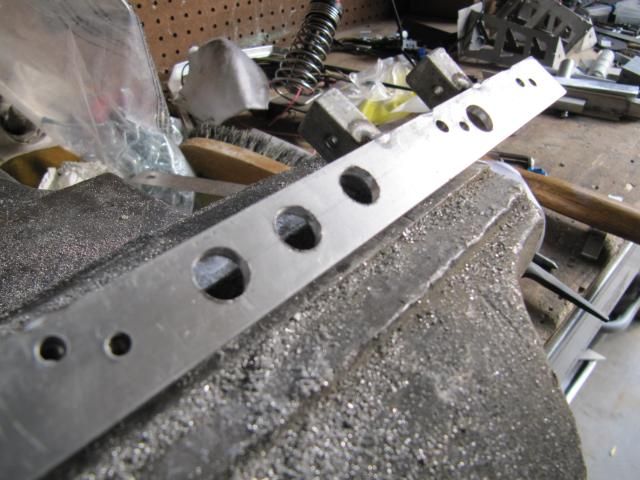
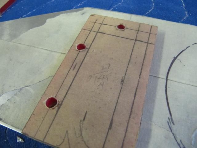
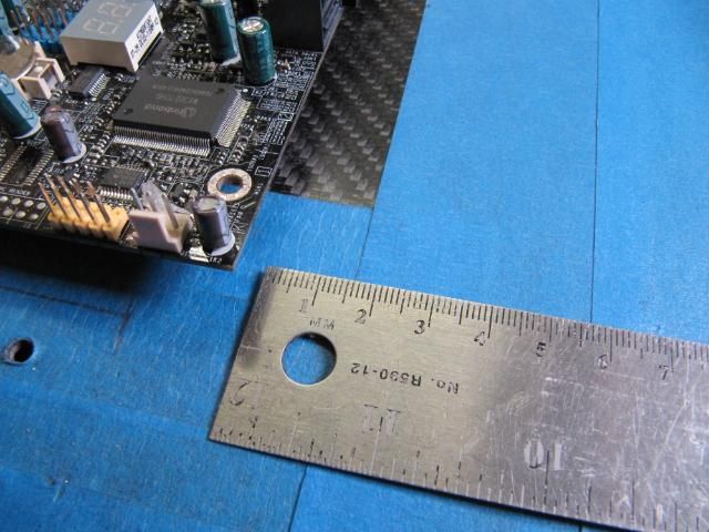
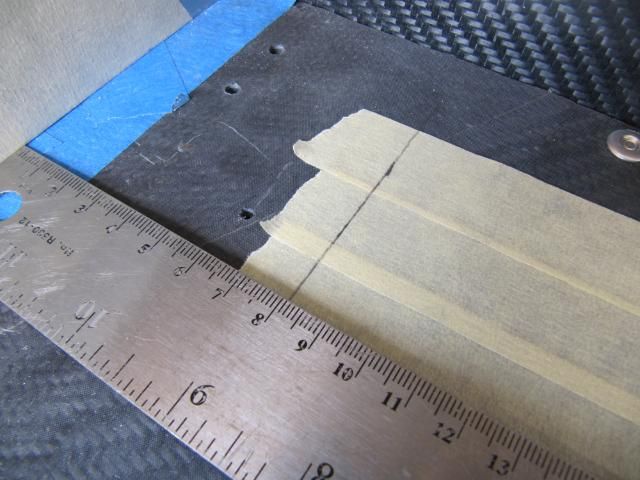
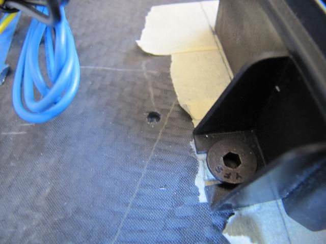
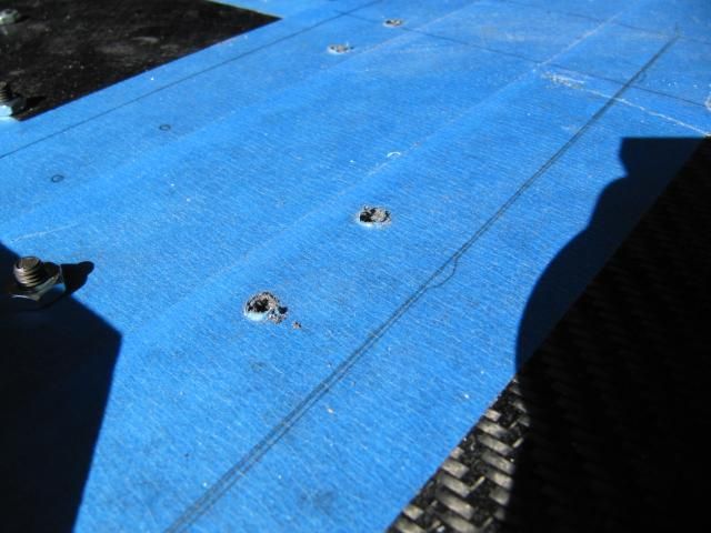
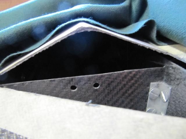
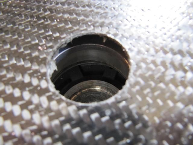
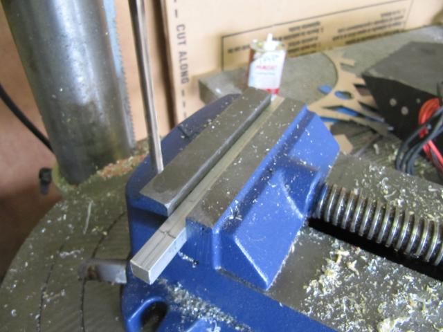
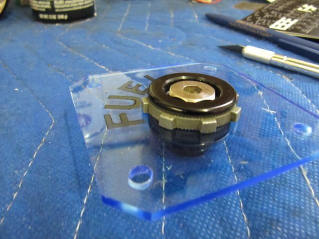
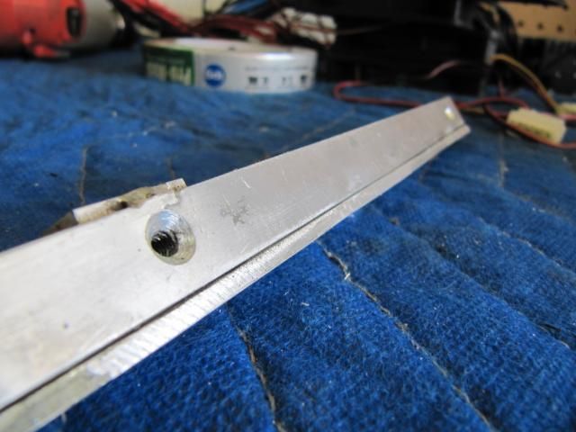
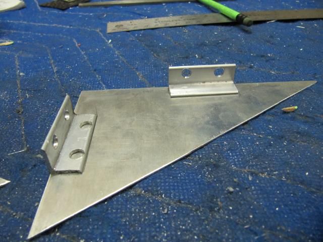
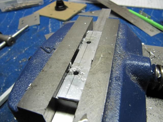
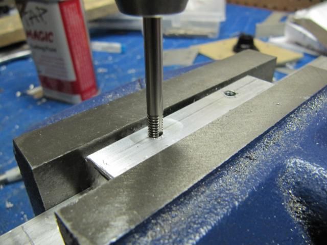
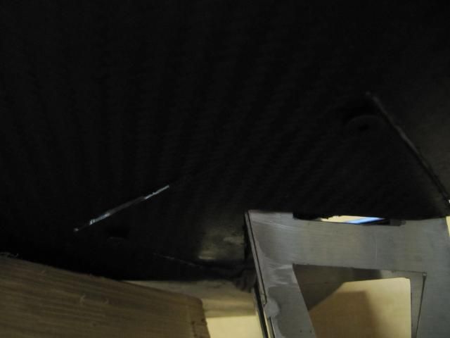
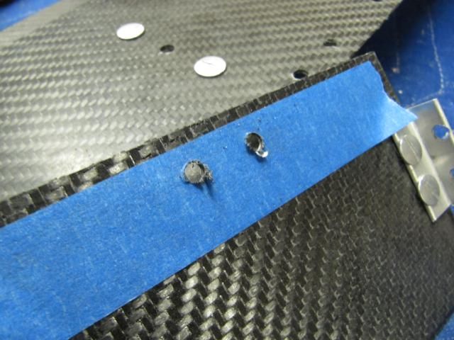
Drilled some holes
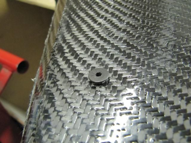
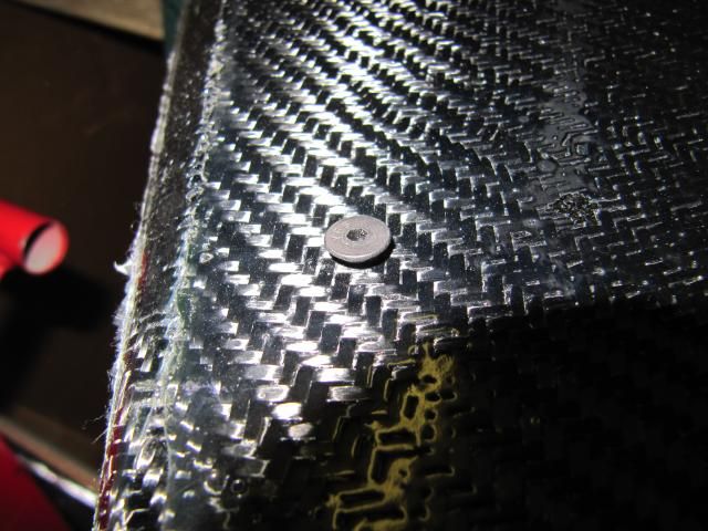
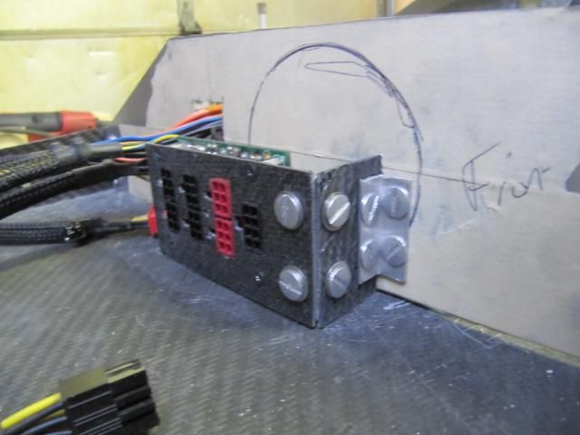
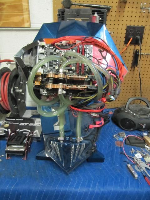
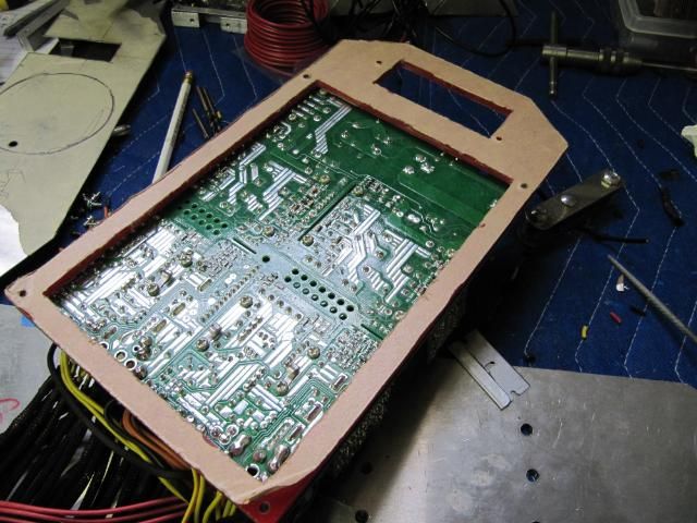
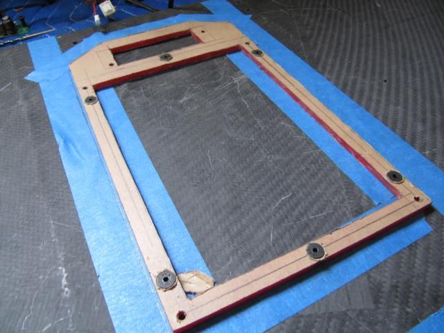
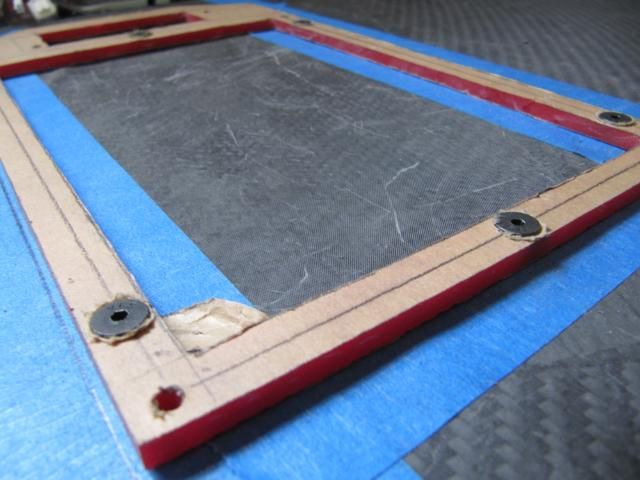
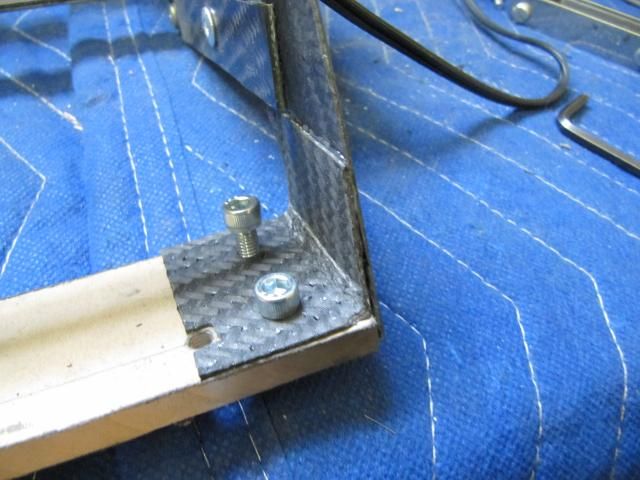
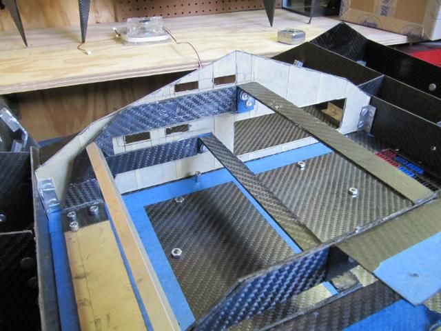
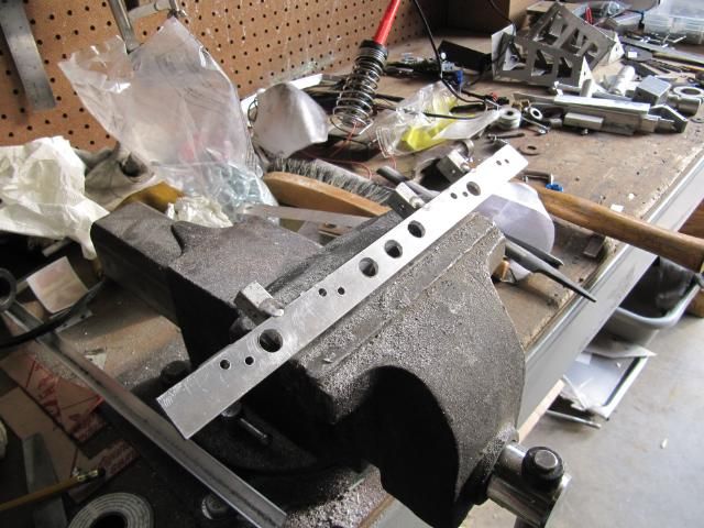
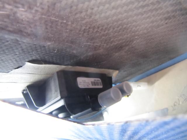
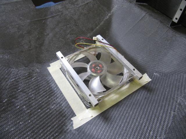
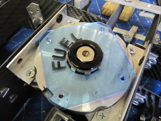
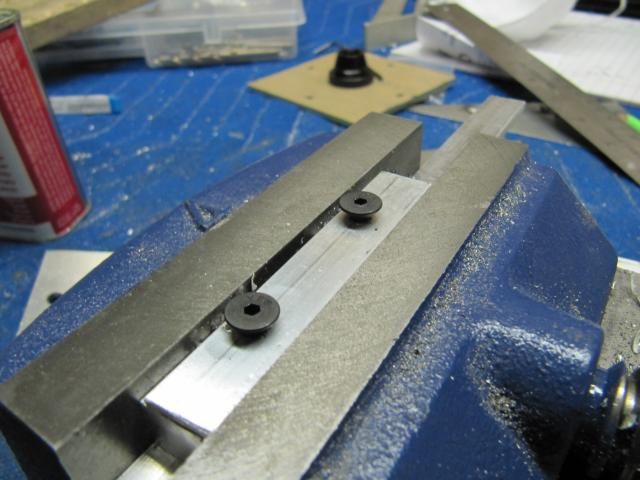
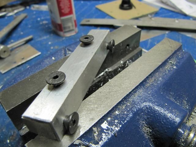
Mounted On.
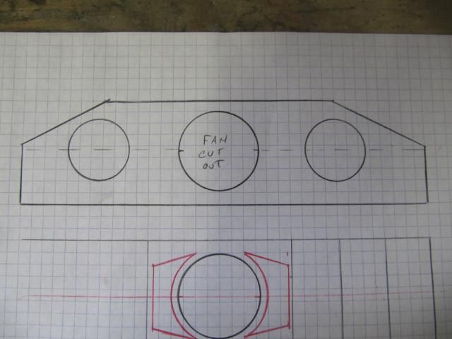
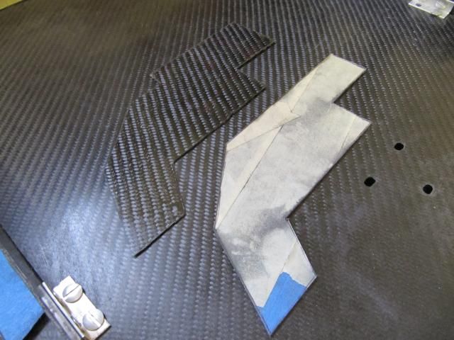
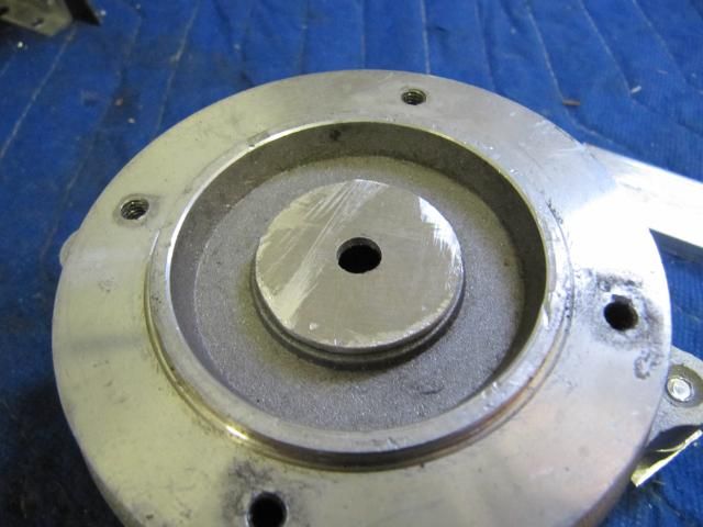
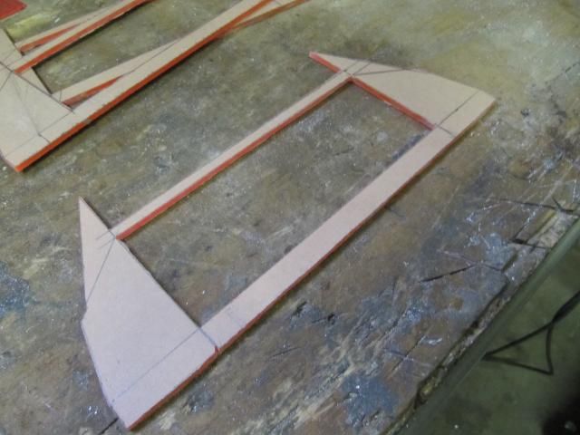
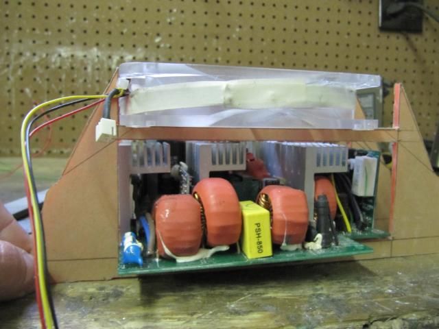
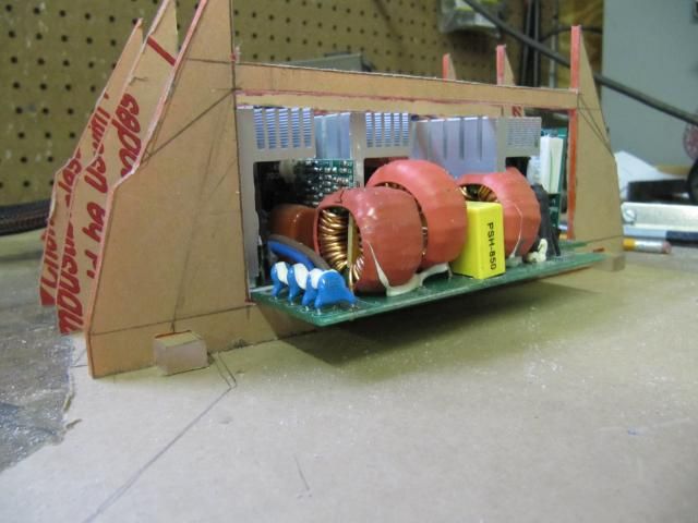
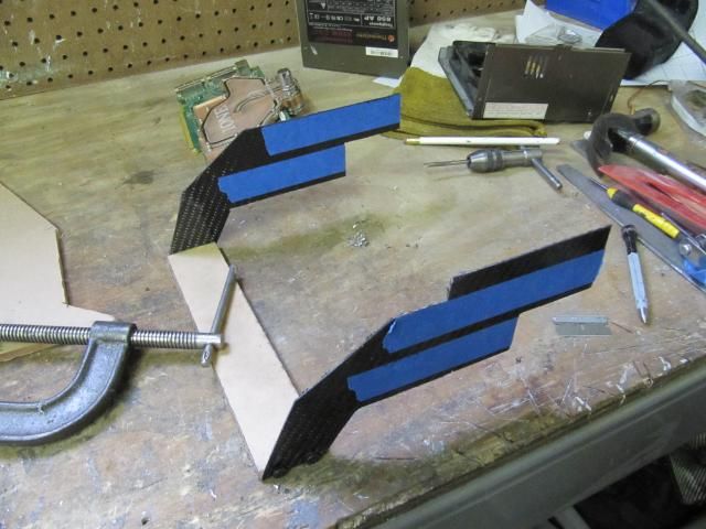
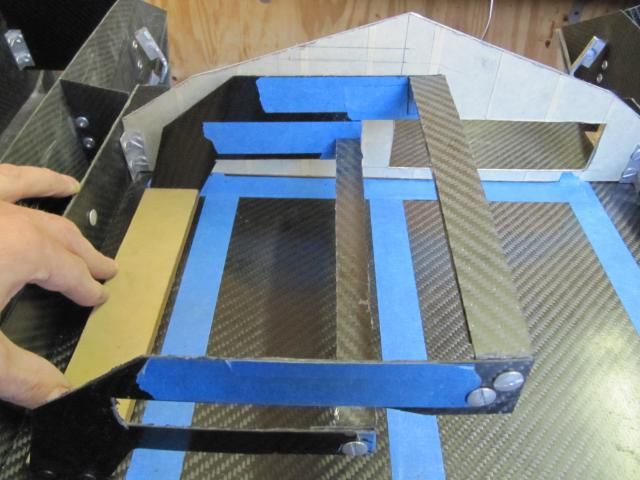
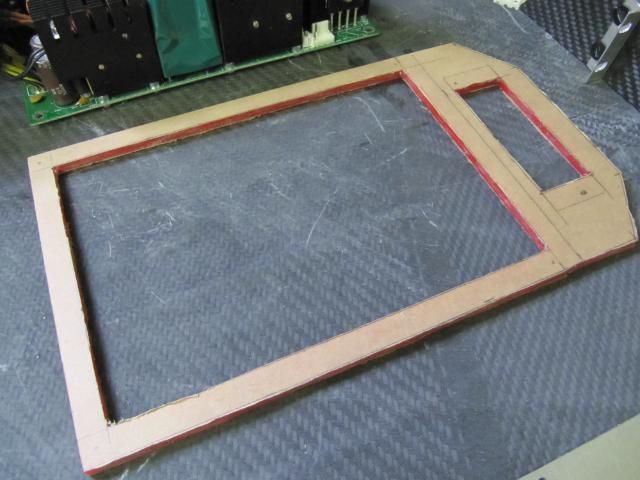
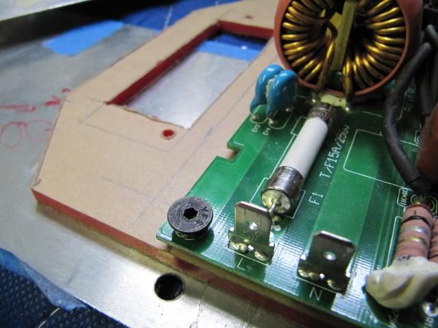
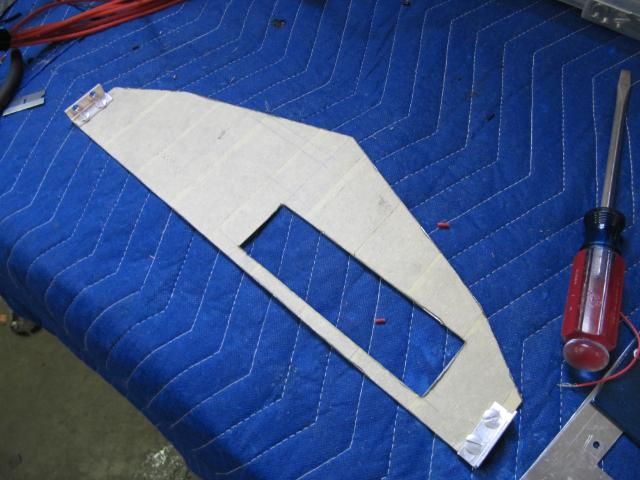
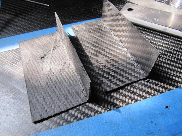
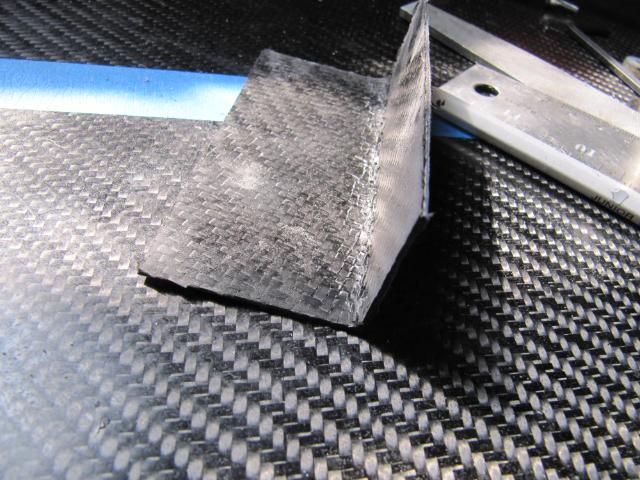
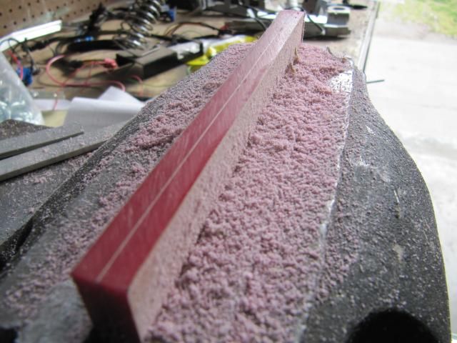
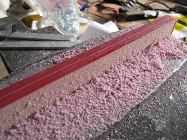
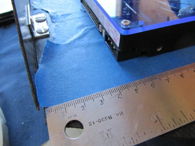
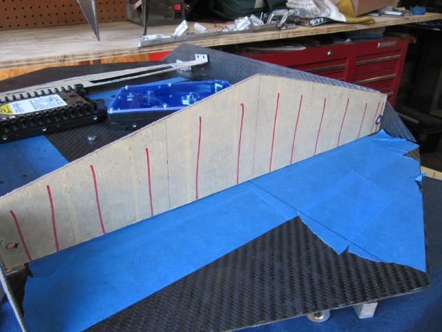
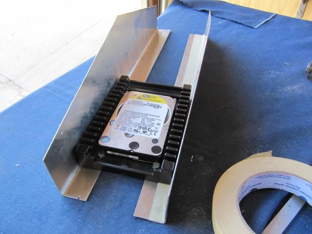
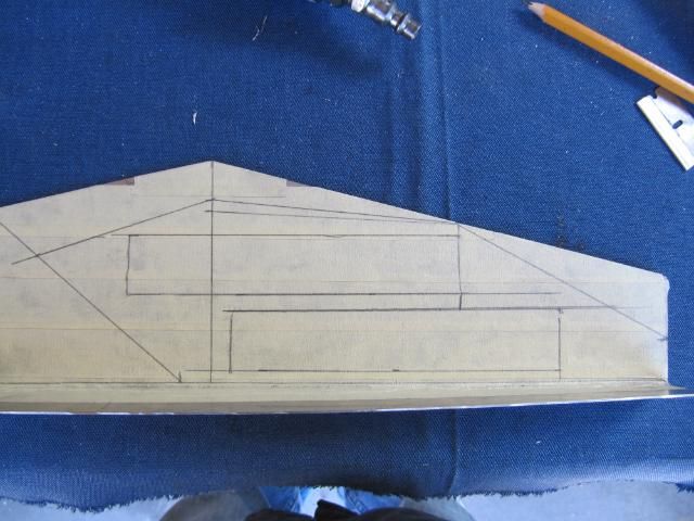
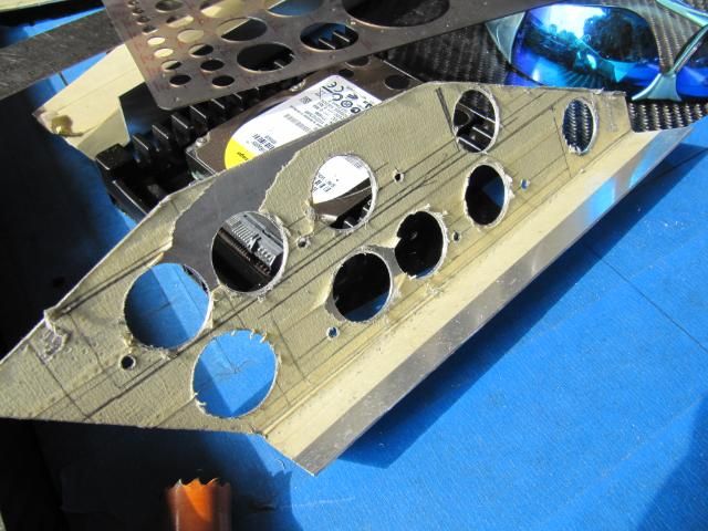
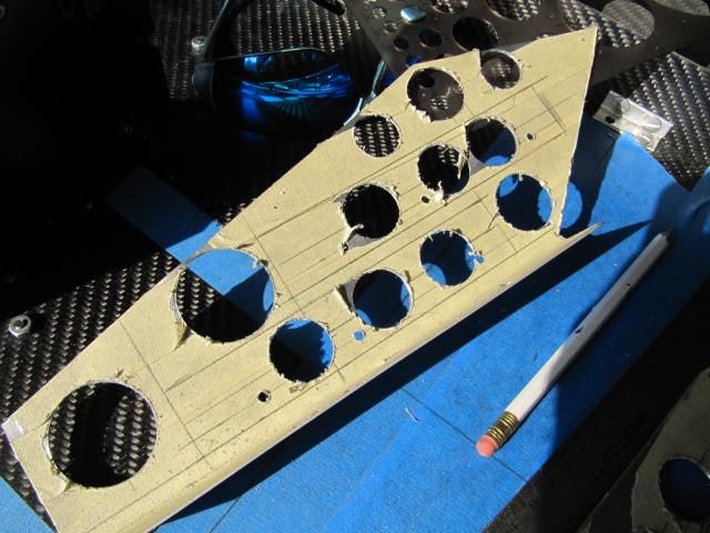
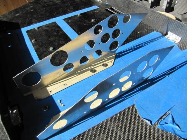
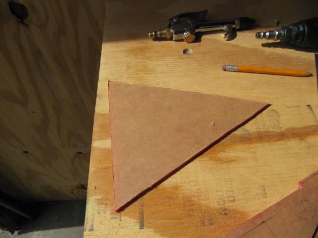
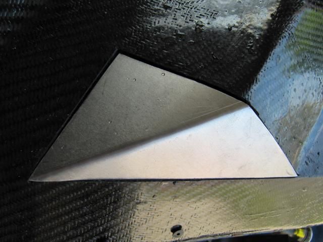
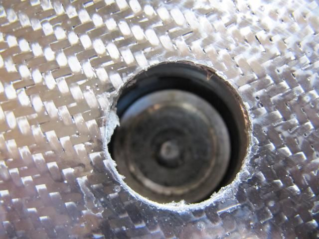
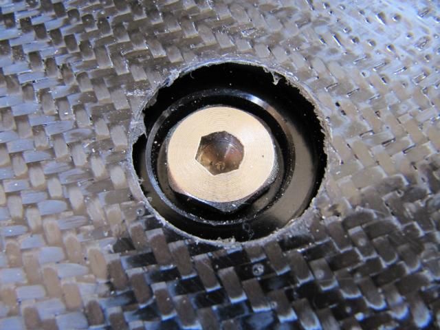
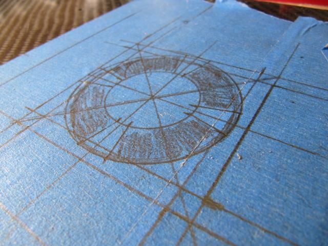
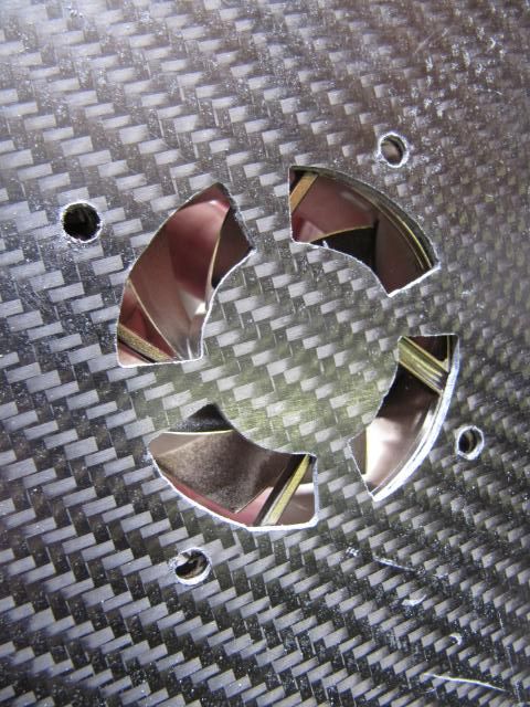
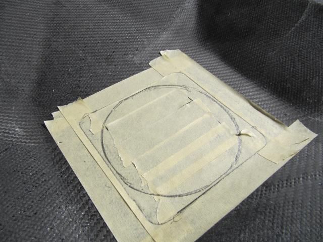
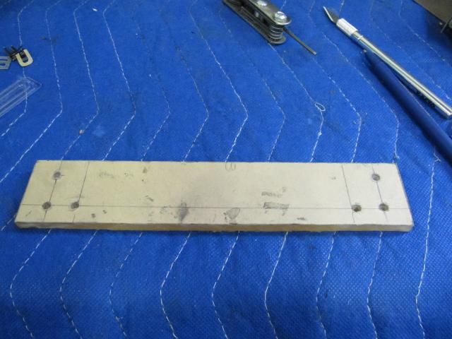
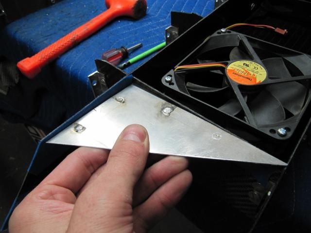
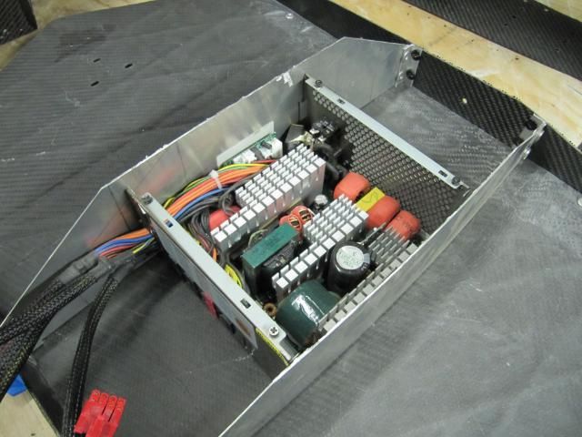
I went back today and started to finishing working on the covers for the case feet.
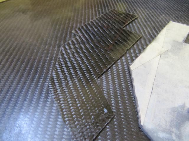
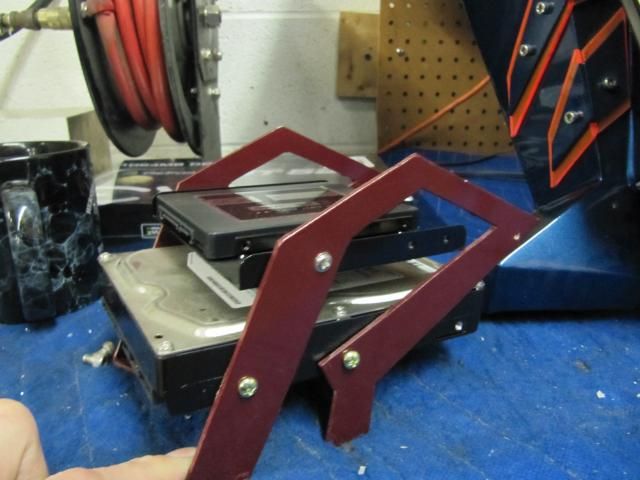
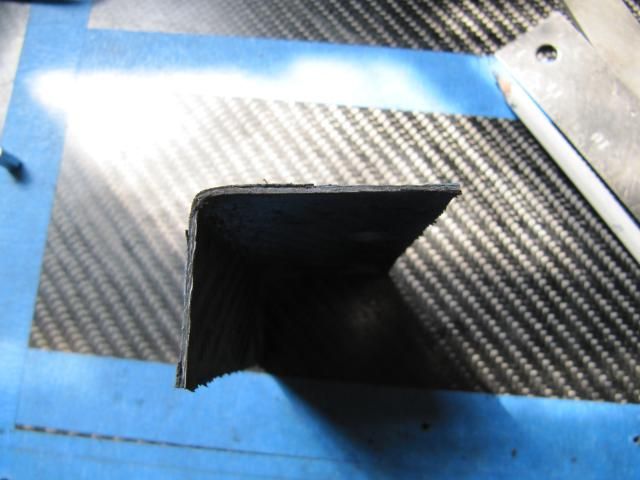
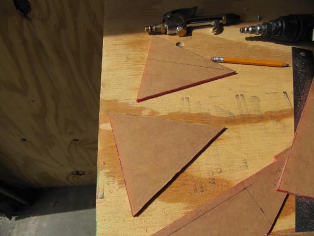
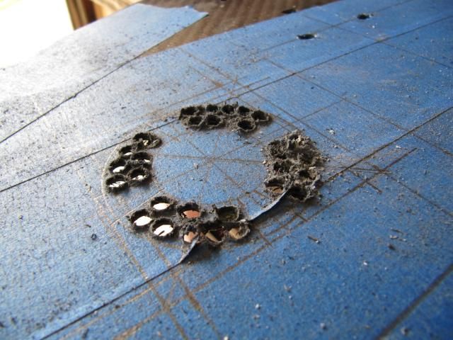
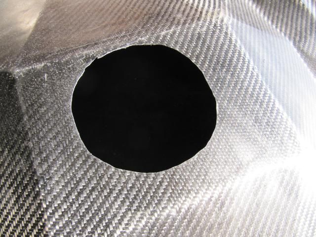
Both feet got cut out. Pics for only the right side foot here. I'll be updating with you more.
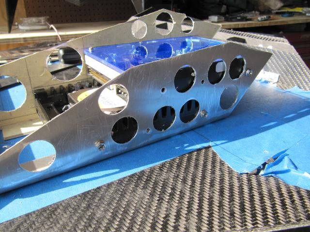
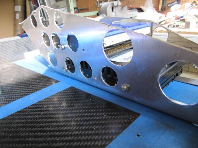
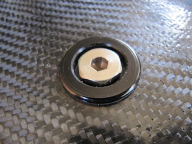
Now I have to fabricate some brackets to hold these covers to the frame. That is tomorrow.
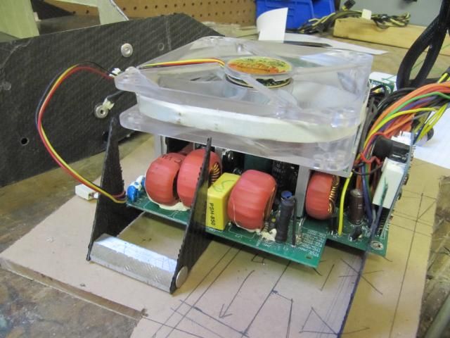
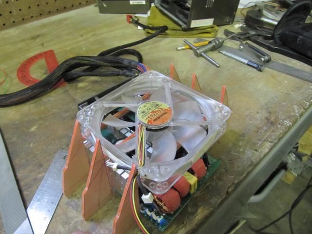
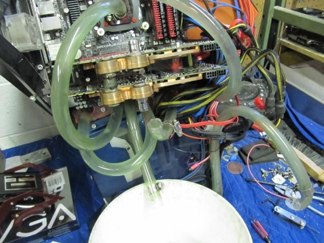
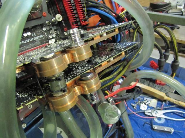
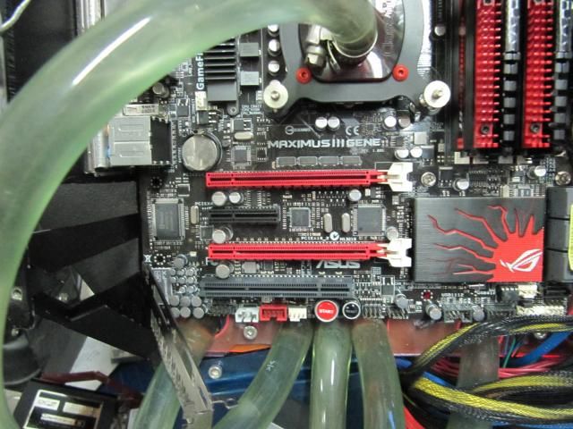
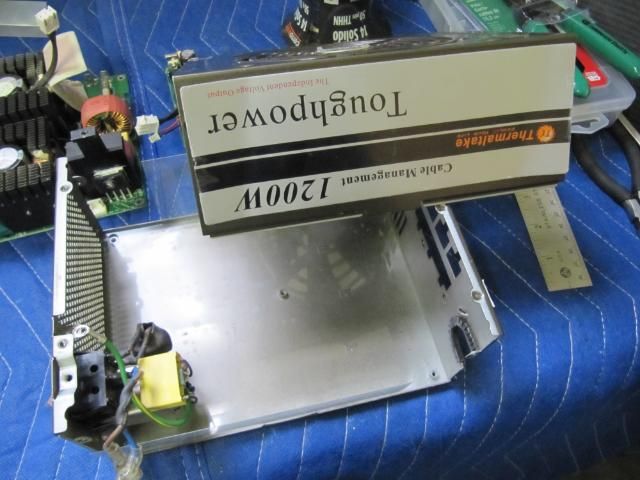
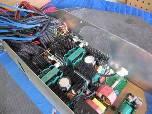
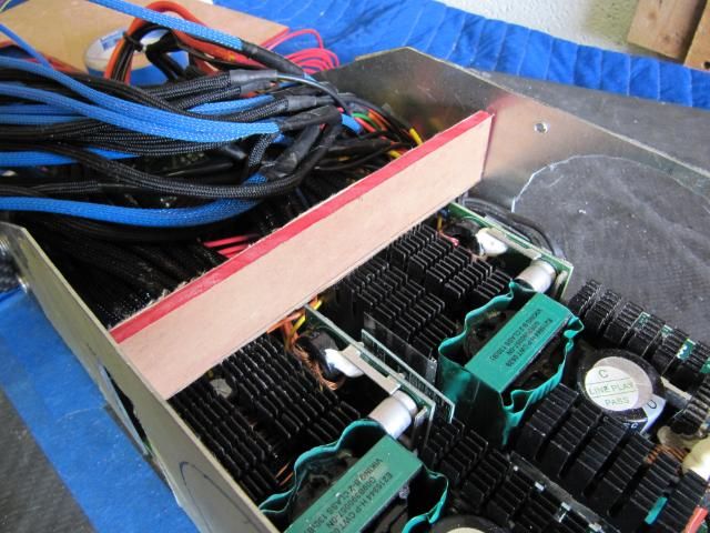
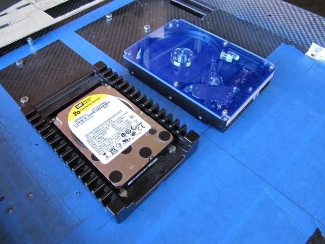
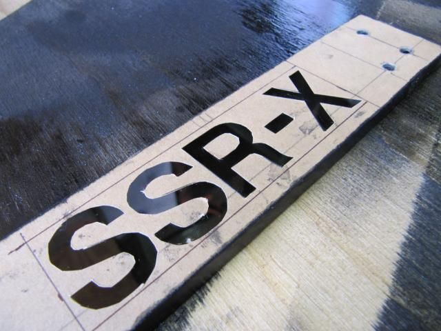
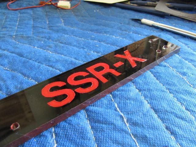
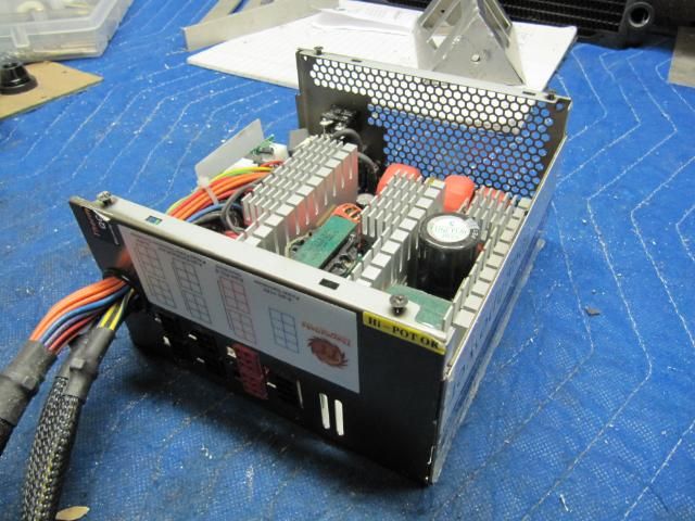
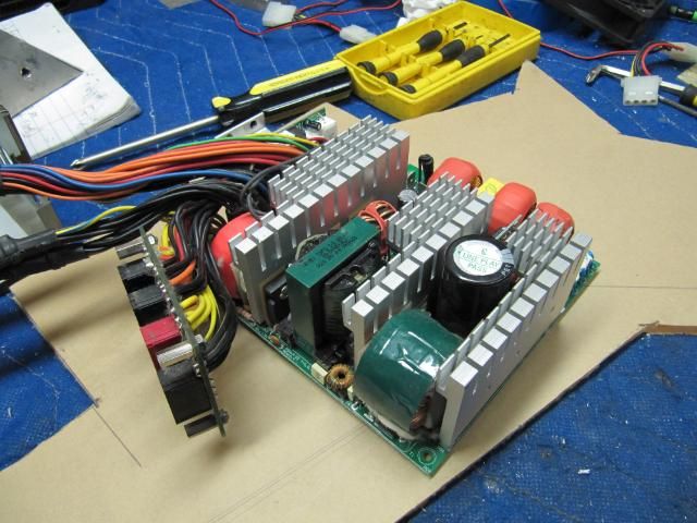
Sneak Peek
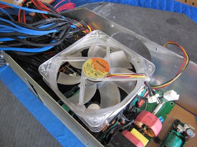
For all the people who DON'T believe me, when I say I'm mounting SSR-X on my truck
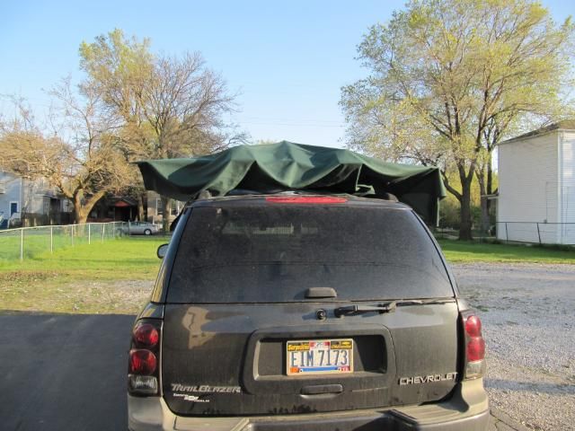
Stay Tuned
These pieces will be for the intake inlet. They will mount to the frame.
There locations
The bracketing that I decided to roll with is simple and lightweight.
Moving onto finishing the wing-tip brackets
So I had to wait the weekend out before I could due get these mounted properly. They need to be welded together. Trying to mount each piece than weld would most likely result in some major misalignment of the covers.
Drilled some holes
Mounted On.
I went back today and started to finishing working on the covers for the case feet.
Both feet got cut out. Pics for only the right side foot here. I'll be updating with you more.
Now I have to fabricate some brackets to hold these covers to the frame. That is tomorrow.
Sneak Peek
For all the people who DON'T believe me, when I say I'm mounting SSR-X on my truck
Stay Tuned
")