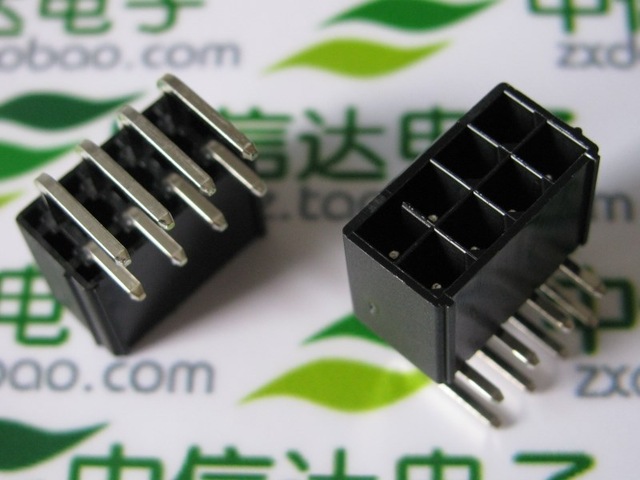
[Video card Mod] Replacing pci-e power connector

MGCJerry

Limp Gawd
Joined
Sep 18, 2005
Messages
144
I've been wanting to put my computer build into a 3U rackmount case and everything will fit with the exception to my video card (RX 460). My pci-e power connector is on top edge of the card and this will prevent the build from fitting inside the case. It would fit in a 4U, but I have a 3U already. I've been loosely trying to source a new power connector for the board but haven't had any luck at finding a part. I've found plenty of 90deg connectors, adapters, splitters, but no vertical board connectors. My full intentions is to remove the old 90deg connector, and installing the new straight one directly on the other ("solder") side of the board.

Anyone know were to get some of these? I've already trawled countless pages on digi-key looking for connectors and ebay/amazon/google search yields pages and pages of what I'm definitely not looking for. I'm already half tempted to fit an entirely different connector and making this connection with non-pc related parts.
 
I'll do a quick search on mouser, but iirc you want the Molex mini-fit jr power connectors.

***edit*** looks like pendragon beat me to the punch.
 
Make sure you get the polarity right, else you're going to have a charcoal briquette.
 
Its going to be some time before I get to the swap. Not much for pictures, just my workstation build placed into a rackmount case to clear up room on my desk. I'm pretty sure I wont be able to make use of my swiftech water cooling loop, but we'll see. My power monitoring system takes a higher priority so that longer term project takes preference.

Though its unrelated to this task the power monitoring system is centered around a Satec PM172E monitor where I'm going to build a PDU box that will measure line voltages, amperage and overall usage more than my UPS can. Its actually a 3 phase power monitor.

• L1 will be "overall line" usage. I'll be installing a CT (current transformer) on the line coming into the box.
• L2 will be "ups" usage. This line will have a CT on and a receptacle installed in the PDU box that my UPS will plug into. This will give me UPS usage reading. I will also be employing a latching relay that as long as I have mains power, it will give an overall power draw of the UPS. On power failure, the relay will switch to another CT, and voltage contact that will be installed AFTER the UPS feed to my main PDU plug strip. That will give me power draw off the UPS as well as UPS voltage.
• L3 will be "non-UPS" line. This will simply measure power draw and voltage on my PDU plug strip.
• The system will also contain an EPO connection (to shut off the UPS) & shunt trip (to kill *everything*) in the event of a serious issue (manual test, over temp, severe over load such as a short, or even smoke). The Satec meter and the UPS will have "Alarms" configured to close a dry contact to cause a system power off, and audible alarm.
• Also to note about the above project & disclaimer... Ive been an electrician for nearly 16 years and had my hands in plenty of lighting control and industrial control systems as well as custom industrial controls through the company I work for. I'm familiar with high voltages (my version of high voltage is 480) and feel comfortable with working with high voltage. While this power monitoring box isn't going to be UL listed, I feel comfortable and confident enough with my abilities to make use of such as system. This project is not recommended with inexperienced people, especially with PTs and CTs in use (CTs can be incredibly dangerous mishandled). I do intend to get pictures of this system during construction and completion. ;)

Once that system above is in-place then I'll be moving onto moving my workstation into the case. My main server is kind of using the case right now unless I get another 3U case (still considering it).
 
probably be easier to just make a pigtail that is soldered to the card.
 
I just looked at an 8pin socket, you could straighten out the pins and cut off the excess and then solder it so it aims vertically.
50pcs-New-PC-PCI-E-Video-Card-8pin-90-Degree-Pin-Solder-Female-Socket-Connector.jpg_640x640.jpg


Maybe you could unpin your connector, straighten out the pins so they aim upwards and then just slide the connector back on.
Now that I think about it, you may have to unsolder and cut the 4 long pins and solder them back in.
 
Back
Top