Thermaltake Grand RGB 1200W Platinum PSU Review @ [H]

FrgMstr

Just Plain Mean
Staff member
Joined
May 18, 1997
Messages
55,626
Thermaltake Grand RGB 1200W Platinum PSU Review

When you start getting into high power PSUs, there are simply not a lot of brands you should trust expensive hardware to. Thermaltake is one of the oldest high power PSU sellers. Do the Frag Harder Disco Lights help it out when we put it on the load tester? No. Does TT still have the PSU chops to hang at 1.2 kilowatts? Yes, it surely does.
 
Do the integrated LEDs take away from the power rating? Isn't this really I 1199W PSU :b Also there is only like 1 case series (also by Thermaltake) where you can really show this off, the P3/5 series open frame chassis.Then again I own a white power supply so who am I too talk bad about the rave power house.
 
"the topology today is similar in that it is a full bridge LLC resonant design"
From where does your guy regularly cut and paste this line of bulloney?
Seems like he finds a way to work into every supply review regardless of
brand, so unlikely coming from the manufacturer.

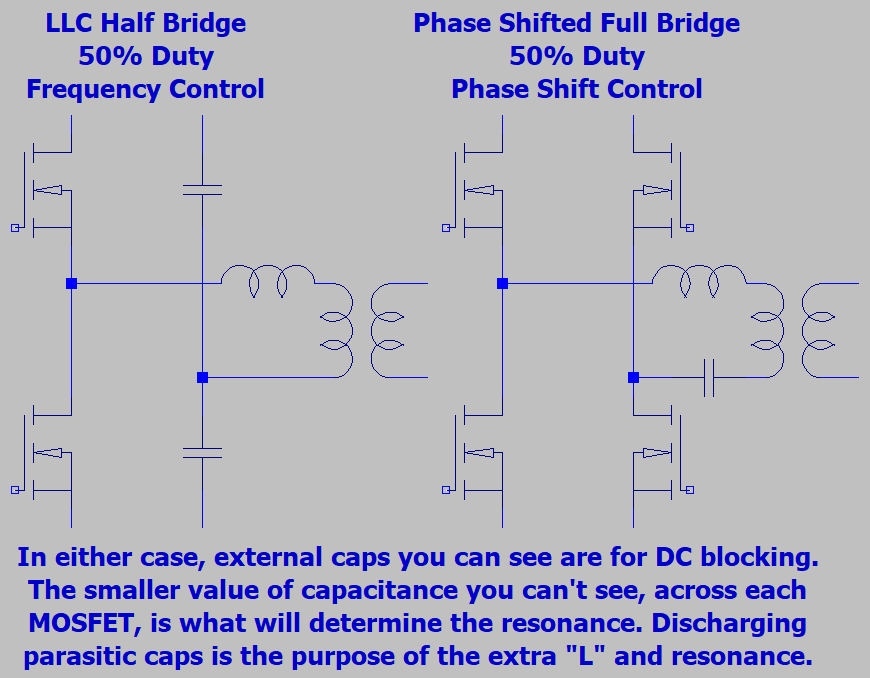
Make up you damn mind: Phase Shifted Full Bridge? Or Half Bridge LLC?
Cause control schemes are completely different, it would be unreasonably
complicated and needless for the primary side circuit to try and do both.

LLCvs.png


Because fewer lossy parts, LLC should be the most efficient at full load.
Because control doesn't depend upon high frequency, a Phase Shifted
Full Bridge could be more efficient, but only at extremely low load.

Even assuming perfect lossless Zero Voltage Switching, a Full Bridge
has twice as much series resistance, and twice as many drive circuits.
No efficiency reward to control a full bridge with rising frequency, as-if
it were an LLC. Which is why it makes no sense to call it one. What I
see in your pics looks more likely Half Bridge LLC.

I havn't seen Full Bridge in a PC supply yet, because extra transistors,
drive, and control circuits are more expensive than passive parts. And
even though the choke isn't needed for high frequency blocking, might
need a choke anyway, to insure Zero Voltage Switching at low load.
So, no passive parts are actually saved.

-----

Thermaltake's supplies work just fine. But the included cables are garbage
and will melt at the modular end. Twice this mode of failure has burned up
a socket of my supply and possibly voided the warranty. But the supply is
durable enough, and the unburned remainder keep working.

Don't know what use a lengthy warranty might be for a supply that comes
sabotaged to void itself with fire starter cables. Try to RMA, I dare you!
I keep buying them cheap, and not had to toss one over anything critical
burning up, yet...

Be extremely cautious of how much load you put on each cable.
 
Last edited:
"the topology today is similar in that it is a full bridge LLC resonant design"
From where does your guy regularly cut and paste this line of bulloney?
Seems like he finds a way to work into every supply review regardless of
brand, so unlikely coming from the manufacturer.

Make up you damn mind: Phase Shifted Full Bridge? Or Half Bridge LLC?
Cause control schemes are completely different, it would be unreasonably
complicated and needless for the primary side circuit to try and do both.

View attachment 69293

Because fewer lossy parts, LLC should be the most efficient at full load.
Because control doesn't depend upon high frequency, a Phase Shifted
Full Bridge could be more efficient, but only at extremely low load.

Even assuming perfect lossless Zero Voltage Switching, a Full Bridge
has twice as much series resistance, and twice as many drive circuits.
No efficiency reward to control a full bridge with rising frequency, as-if
it were an LLC. Which is why it makes no sense to call it one. What I
see in your pics looks more likely Half Bridge LLC.

I havn't seen Full Bridge in a PC supply yet, because extra transistors,
drive, and control circuits are more expensive than passive parts. And
even though the choke isn't needed for high frequency blocking, might
need a choke anyway, to insure Zero Voltage Switching at low load.
So, no passive parts are actually saved.

-----

Thermaltake's supplies work just fine. But the included cables are garbage
and will melt at the modular end. Twice this mode of failure has burned up
a socket of my supply and possibly voided the warranty. But the supply is
durable enough, and the unburned remainder keep working.

Don't know what use a lengthy warranty might be for a supply that comes
sabotaged to void itself with fire starter cables. Try to RMA, I dare you!
I keep buying them cheap, and not had to toss one over anything critical
burning up, yet...

Be extremely cautious of how much load you put on each cable.

I am not sure how you get that from the pictures as you can not see the primary power components on the heatsink completely in the picture as I did not remove the coils that are in the way for the picture. Technically the CWT platform used in this unit is the same as the Toughpower iRGB 1250W minus the USB controller. The primary topology is an interleaved PFC full-bridge LLC resonant design; it is not half bridge (unless CWT has done something funny to use two switch pairs). The controller used in this unit is the TI UCD3138 which supports LLC half bridge and LLC full bridge implementations. This general primary topology CWT and Thermaltake have been using since at least 2011 with the Toughpower XT Platinum 1275W. There are a number of other brands/OEM's with a similar full bridge primary designs such as Seasonic, Corsair, Enhance, Antec, etc. Full bridge designs are generally only seen in higher powered units because of cost (sort of like how DC-DC VRM's are more expensive than independent regulation or group regulation but provide for better performance than group and higher efficiency until you can get economies of scale of course) but they have been part of the massive drive in efficiency over older double forward or even active clamp reset forward designs. They are not uncommon.
 
The full bridge has twice as much resistance drain to source, and twice
as many drive circuits. At full load it is definately not more efficient. It is
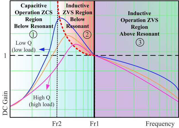
only more responsive to control, since change of phase has linear effect
upon overlapping duty cycle of the switches. While changing frequency
to trick passive LLC components into blocking is not a linear thing at all.

Gain-curve-of-LLC-converter.png


A slow control loop to keep LLC from going nuts and making an oscillator
is maybe the best excuse for going full bridge. To control by phase shift
offers the possibly of much faster response to load change. Driving a full
bridge like an LLC offers all the weirdo control loop disadvantages with
none of the efficiency benefits. Why I say most likely isn't doing both.

Can't determine which is which just by seeing a UCD3138. It depends
which firmware was loaded (something I had to do yesterday). I can't
go into specifc details about test procedures, but you can probably
figure most of what happens in my lab from the user's guide. I don't
design any of TI's stuff, just test...

https://store.ti.com/UCD3138ALLCEVM150-UCD3138A-LLC-Evaluation-Module-P44126.aspx

If you say you have counted four transistors, and are sure about that,
then maybe it could be a full bridge. Can't imagine why though. Any
possibility those are half bridge wired in parallel to reduce RDS loss?

Other complications in determining the circuit topology are that both
L's of an LLC could be intergrated into one, just by a sloppy winding.
Not that winding black arts seem to apply in this case. C that matters
for resonance is a parasitic property of the MOSFETs. Not the DC
blocking cap more easily identified. And the shim choke of a phase
shifted full bridge (for storing energy to discharge MOSFETs) might
appear the same as the blocking choke of an LLC.
 
Last edited:
The full bridge has twice as much resistance drain to source, and twice
as many drive circuits. At full load it is definately not more efficient. It is
only more responsive to control, since change of phase has linear effect
upon overlapping duty cycle of the switches. While changing frequency
to trick passive LLC components into blocking is not a linear thing at all.

View attachment 69752

A slow control loop to keep LLC from going nuts and making an oscillator
is maybe the best excuse for going full bridge. To control by phase shift
offers the possibly of much faster response to load change. Driving a full
bridge like an LLC offers all the weirdo control loop disadvantages with
none of the efficiency benefits. Why I say most likely isn't doing both.

Can't determine which is which just by seeing a UCD3138. It depends
which firmware was loaded (something I had to do yesterday). I can't
go into specifc details about test procedures, but you can probably
figure most of what happens in my lab from the user's guide. I don't
design any of TI's stuff, just test...

https://store.ti.com/UCD3138ALLCEVM150-UCD3138A-LLC-Evaluation-Module-P44126.aspx

If you say you have counted four transistors, and are sure about that,
then maybe it could be a full bridge. Can't imagine why though. Any
possibility those are half bridge wired in parallel to reduce RDS loss?

Other complications in determining the circuit topology are that both
L's of an LLC could be intergrated into one, just by a sloppy winding.
Not that winding black arts seem to apply in this case. C that matters
for resonance is a parasitic property of the MOSFETs. Not the DC
blocking cap more easily identified. And the shim choke of a phase
shifted full bridge (for storing energy to discharge MOSFETs) might
appear the same as the blocking choke of an LLC.

I kind of doubt they are in parallel. I can think of a few reasons why full bridge would be used instead. Start with the power output, it is 1200W and while you can design a half-bridge unit to deliver that output it is not in its "sweet spot". Then sourcing components that you need to get your design characteristics out of it en mass is going to be a bit challenging. Take the switches for instance. In a half bridge design they are going to be rated for and have to handle much more power than in full bridge which means more heatsinks and potentially more expensive components on a per unit basis. Or the transformer size you will need on a half bridge versus a full bridge. So while 4 is greater than 2 it won't be as straight forward when you look at all of the component availabilities, individual component specs, and ancillary needs to support those components. Then there is the initial general design step. This unit is full range so you are going to see AC input voltages down to 90V and typically you can drive higher efficiency from a full bridge unit than a half bridge (though their ranges do overlap). So, if you want to build a high powered unit that is going to be very efficient with the potential for low AC input voltages and you optimize your design with the right components accounting for all costs and space constraints in your design full bridge does work very nicely. It all comes down to optimizing design.....there are a lot of ways to get there.
 
First of all:
Active PFC presents 380VDC +/-20V at the bulk capacitor, regardless of AC input
voltage. Arguments assuming the bridge operates from a lower voltage are invalid.

Secondly:
Transformers would be identical. Glopped with the same sweet and sour sauce.
Chokes beside them maybe, maybe not...

Thirdly:
In a full bridge, two transistors (one on each side of the bridge) must be enabled
in series with the transfomer primary winding to complete either the charging or
freewheeling circuits. Else diodes will be forced to conduct freewheeling current,
and since they are part of the very same transistors, not like they get much rest.

The average current through the transformer is about same as for the half bridge.
Series transistors carry the same current, not halving between them. Therefore,
a full bridge dissipates twice as much in transistor (and transistor driver) losses.

Actually some get slightly hotter than others, and I can't remember right now the
exact pattern. I don't want to be caught wrong making up reasons why, so I need
to actually look this up before I say something stOOpid.

Remember:
I'm not an engineer, I just test the shit...
If you are local enough to Plano, I would be happy to show you.

-edit-

I may have already gone stOOpid at "Secondly". As the half bridge offers only
half as much working voltage across the transformer primary, they could not
be identical at the same power level. I need to STFU and rethink whether my
other conclusions "Thirdly" still make sense.
 
Last edited:
I thought about this on the drive home, and this is what I've concluded:

The transformers can only be identical if there are two primary windings,
and we have the option to wire in series for full bridge (double voltage)
or parallel for half bridge (double current). Doesn't seem likely in a supply
designed for one purpose. But I have seen plenty of dual primaries, and
never stopped to ask why they were sometimes made that way.

Either way we need four independant transistors for full bridge, or two
pairs in parallel for half bridge. No difference in efficency either way.
Half bridge might require only two drive circuits, but they would each
be working twice as hard.

However, only the full bridge offers all options: Phase shift control,
"LLC" frequency control, or both simultaneously. Frequency control
does not seem very helpful. Nor does both, only complicating.

I still don't think curvy LLC control scheme makes much sense for a full
bridge that has a more linear phase shift control option to choose from.
Curvy=slow, because you have to make the control loop stable around
the worst case on the curve. And that represents not most of the curve...

UCD firmware might be unbending those curves? but I have no special
insight as to how the UCD might be programmed, nor if that makes the
control loop more stable. All they tell me is how to flash the blank chips.

We should put one of these on the scope and see what it actually does.
I got differential probes that can safely handle the high side of a bridge.

My TT's are the Toughpower 850 RGB, and warranty already voided by
melting/charring damage to the modular SATA/MOLEX periperal socket.
Thermaltake's periperal power cables can't even handle a pair of 1050ti
for too long before starting a smokeout.

If my 850 are not internally similar to 1200, then we need to measure
yours. Warranty obviously voided by taking it apart for review, unless
you had some special arrangements with TT in advance.
 
Last edited:
Parametron has the same components as an LLC.
Obviously both are Limited Liability Corporations.
Never worry the small details. News makes fact.
 
Last edited:
This guide gives better explanation than any of my drawings.
 

Attachments

  • 10 PSMA PTR 2014_10_02 Power Converter Topology Trends Mappus Fairchild.pdf
    1.1 MB · Views: 0
Back
Top