24" Widescreen CRT (FW900) From Ebay arrived,Comments.

It sounds like you pretty much narrowed down the issues, but I still might give it a try later. I use Lubuntu on my laptop, and I've used Live CD's before so I know my way around it somewhat.

I think the next step is having some Nvidia people try some of this stuff.

Okay cool, don't hesitate to ask if you need help testing!
 
Thanks for checking it out. Definitely a driver limit for AMD in Windows. What's strange is that it's giving me different limits for different monitors, even when I'm altering the EDID via CRU. So my best guess here is that AMD is saving some info about the (reported) max capabilities of the monitor and sticking to them even if CRU tries to override. I wish the Sunix would just always report itself to Windows as a 4k display, that would take care of this issue

Have you tried to edit the Display Properties settings under CRU? (edit button)
 
Have you tried to edit the Display Properties settings under CRU? (edit button)

Yeah, I increased the max pixel clock and cleared a spot for it. No go.

I'm thinking I need some sort of spoofer to make this work, something along these lines:

http://www.hallresearch.com/page/EM-EDID-HD15

or

http://www.aten.com/au/en/products/professional-audiovideo/converters/vc010/#.Wm-St5ckojl

The first one is widely avaialable, but the programming cable for it is not, so I wouldn't be able to write a fake EDID with a really high max resolution to it. The second one is too pricey.

Then there are also EEPROM EDID dummy plugs like this that I could use to trick my GPU: https://www.amazon.com/dummy-Headle...qid=1517261736&sr=8-3&keywords=dummy+vga+plug

but it seems all the VGA-based ones are max 1080p, which doesn't help me at all. I would use it in conjunction with the first spoofer I listed, or maybe with a splitter or switch of sorts. I'm currently looking into how hard it would be to make one myself.
 
As an Amazon Associate, HardForum may earn from qualifying purchases.
Yeah, I increased the max pixel clock and cleared a spot for it. No go.

I'm thinking I need some sort of spoofer to make this work, something along these lines:

http://www.hallresearch.com/page/EM-EDID-HD15

or

http://www.aten.com/au/en/products/professional-audiovideo/converters/vc010/#.Wm-St5ckojl

The first one is widely avaialable, but the programming cable for it is not, so I wouldn't be able to write a fake EDID with a really high max resolution to it. The second one is too pricey.

Then there are also EEPROM EDID dummy plugs like this that I could use to trick my GPU: https://www.amazon.com/dummy-Headle...qid=1517261736&sr=8-3&keywords=dummy+vga+plug

but it seems all the VGA-based ones are max 1080p, which doesn't help me at all. I would use it in conjunction with the first spoofer I listed, or maybe with a splitter or switch of sorts. I'm currently looking into how hard it would be to make one myself.

Looking at your first link, it mentions cables that don't support EDID. Just a random thought, lol, did you try switching VGA cables?
 
As an Amazon Associate, HardForum may earn from qualifying purchases.
Ok guys, I decided to get one of the HDMI 2.0 dummy plugs, since HDMI shares the same EDID signals as DVI and VGA. I'll run it through a few passive adapters to get HDMI>DVI>VGA, then to a Extron 460xi which has 1 input, 1 ouptut with ID pins, and 1 without. I'll be running the monitor off the output without the ID pins, and I'll have the 4k HDMI dummy on the on with the ID pins.

You guys think this will work out? Am I going to run into issues if the RGB pins are not connected to anything on the ID-capable input?

Looking at your first link, it mentions cables that don't support EDID. Just a random thought, lol, did you try switching VGA cables?

My P992 definitely has the ID pins, it's name is recognized both through the Sunix and my GPU's native VGA output. If you try to do it without ID signals, it defaults to the sunix's EDID which is 1080p60 max.
 
Ok guys, I decided to get one of the HDMI 2.0 dummy plugs, since HDMI shares the same EDID signals as DVI and VGA. I'll run it through a few passive adapters to get HDMI>DVI>VGA, then to a Extron 460xi which has 1 input, 1 ouptut with ID pins, and 1 without. I'll be running the monitor off the output without the ID pins, and I'll have the 4k HDMI dummy on the on with the ID pins.

You guys think this will work out? Am I going to run into issues if the RGB pins are not connected to anything on the ID-capable input?
That sounds super complicated, lol. I haven't a faintest idea if it will work.
 
I have this issue with my FW900 where it will squish the image in at the sides mostly on the right side, and the image once it squishes too hard will blip and then the monitor shuts off and goes to standby. I presume a faulty capacitor or failing capacitor on the D board. I cannot determine how to fully remove the D board, I have disconnected all cables except the Flyback red and black leads running to the neck board. I cannot figure out how to disconnect those leads.

Anyone have any idea as to either what is causing the image to go out or how to disconnect those leads? Thanks.
 
To disconnect those leads you need first to unplug the A board from the neck of the tube, and then to disconnect the plastic plug of those leads from the main neck plug of the A board (2 clips on the sides).

But for some quick soldering job on the D board it's not really necessary to remove that plug or even the flyback plug, just let the board sit on its heatsinks, standing on a high cardboard box next to the screen.

Now, about the root of your issue, it's hard to tell. As far as I know an image squished in the center of the screen should mean horizontal S-correction capacitors with capacitance too low or drifting in another way (that's something I have on my "to check" list as my "guinea pig" GDM-5410 has that issue). But yours is the contrary, and film capacitors never increase in capacitance with use. Moreover it should be a stable issue, not something eratic.

I think you should check the voltages output on the G board first before messing with anything else. That can be done easily with a common multimeter, putting the red probe on the exposed metallic part of the top plugs, and the black one on the chassis (warning, make sure to only hit one single pin at a time, or you'll make a short and blow fuse resistors).
I've discovered there might be a design fault on the 15V rail, the rectifier bridge seems undersized or sized too close to the current needs. With aging it may not be able to provide enough current anymore, and heat more and more, which is the infernal circle leading to the death of such component.

Thank you good sir. I'm trying my best to learn about all this.

When you mention the rectifier bridge, what are you referring to? Does this supposed design fault apply to the 15v rail on all plugs? Presuming that I can test said plugs while the monitor is off, I will grab a MM and check. The ouput voltages are all coming from the top mounted plugs on the G board so testing all the pins should suffice, I believe.
The rectifier bridge issue is an hypothesis I haven't verified yet, better do not bother with this if you do not understand much of the subject.

Checking the voltages is a first step to know if everything is right. If they are close of the value they're supposed to have (5V, 12V, 15V, 80V, 220V), then it's a good thing, and it rules out any major power supply problem. If they are not all, then it's a start to find out what's wrong. BTW the voltage lines are indicated on the board, no need to test every pin.

Also, the monitor has to be on to check voltages, otherwise it wouldn't be funny. :p

edit: In case you didn't notice, there are two different 5V rails: 1W+5V and STBY 5V. These voltages come from two different regulators so both have to be checked. All the other voltages lines come from a single source each.
 
Last edited:
Well, I should probably refrain from talking about electronics here, apparently it scares people away. :whistle:
 
Well I was able to test out using the 4k HDMI dummy plug to spoof a different EDID. Here's the Extron RGB setup I mentioned, where I run the dummy plug on the output that can read the EDID, and the monitor on the output that doesn't.

suXwsq1.jpg


But the dummy's EDID didn't open up additional resolutions for me. I'm not 100% sure why, but it may be because this particular dummy plug stored it's 4k resolutions in the extension block, and also didn't specify a max pixel clock in the "display properties" section. So I'm either going to overwrite it, or buy something like a Dr. HDMI to make my own EDID
 
So after doing a lot of testing on my new GPU, for whatever reason, I get ripple artifacts and split second blackouts whenever my refresh rate ends with 5 (like 75 Hz, 85 Hz). It's completely fine when it ends in 0 (like 70 Hz, 90 Hz, 100 Hz). I didn't try like 72 Hz. Anyone else have the same issue? My new GPU is an AMD RX 480.
 
Aktan

Might be an issue with your monitor? My Lacie has major geometry issues with 2048x1536@85hz, but not at 84hz, 86hz, etc. And it's there whether I feed it from the sunix or GPU vga out.
 
Aktan

Might be an issue with your monitor? My Lacie has major geometry issues with 2048x1536@85hz, but not at 84hz, 86hz, etc. And it's there whether I feed it from the sunix or GPU vga out.

Nah, it happens on both of my monitors and they are different brands. One is a ViewSonic G225f and the other is a Sony Multiscan G500. I actually think it's more related to my GPU and running dual monitor than anything. Lots of funky things happen on AMD with dual monitor. I don't know if NVidia cards have the same problem.
 
So after doing a lot of testing on my new GPU, for whatever reason, I get ripple artifacts and split second blackouts whenever my refresh rate ends with 5 (like 75 Hz, 85 Hz). It's completely fine when it ends in 0 (like 70 Hz, 90 Hz, 100 Hz). I didn't try like 72 Hz. Anyone else have the same issue? My new GPU is an AMD RX 480.

I had ripple effects when I was not using USB power, they went away when plugged in.
 
I had ripple effects when I was not using USB power, they went away when plugged in.

Yep, I think you mention this earlier. I tried with USB power from motherboard, and USB power from a USB brick (some old phone charger). I still got ripples. Only time they went away was when I change the refresh rate. Again, maybe it's related to the GPU. I did notice that with USB power, the blackouts happen less. One time I had blackouts like twice a second, every second, which was lessen when I connected USB power.
 
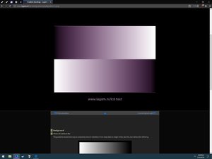
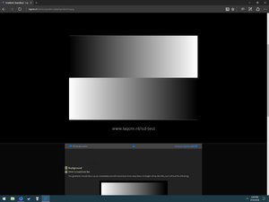
I'm having quite a peculiar issue here. I just switched from my FW900 to a Mitsu 2070sb and I noticed that certain shades of grey and black have a purple tint to them. However, I realized that the issue only appears in web browsers. Firefox and chrome are affected but they render stuff completely different. Whereas edge isn't affected at all and renders everything correctly. What the hell is going on?

EDIT: attached images
It's kind of silly considering that the reference image below renders correctly in both browsers.
 

Attachments

  • firefox.jpg
    firefox.jpg
    110 KB · Views: 35
  • edge.jpg
    edge.jpg
    94.7 KB · Views: 39
Last edited:
I'm having quite a peculiar issue here. I just switched from my FW900 to a Mitsu 2070sb and I noticed that certain shades of grey and black have a purple tint to them. However, I realized that the issue only appears in web browsers. Firefox and chrome are affected but they render stuff completely different. Whereas edge isn't affected at all and renders everything correctly. What the hell is going on?

EDIT: attached images
It's kind of silly considering that the reference image below renders correctly in both browsers.

Funny, I was at that site yesterday to calibrate my monitor, lol. Anyway, I'm on FireFox and it's correct. I notice your FF icon at the bottom is also a different color. Is that Waterfox? Besides that, I have no idea why it would do that. Honestly I think it's a software issue (GPU drivers) and not a hardware one since it works fine in Edge.
 
Funny, I was at that site yesterday to calibrate my monitor, lol. Anyway, I'm on FireFox and it's correct. I notice your FF icon at the bottom is also a different color. Is that Waterfox? Besides that, I have no idea why it would do that. Honestly I think it's a software issue (GPU drivers) and not a hardware one since it works fine in Edge.

It's firefox nightly but chromium was also affected(to an even greater degree lol).
The funny thing is that on my FW900 all browsers render fine. Well, I don't mind as long as everything else is fine but it's really strange.
 
It's firefox nightly but chromium was also affected(to an even greater degree lol).
The funny thing is that on my FW900 all browsers render fine. Well, I don't mind as long as everything else is fine but it's really strange.

It is really strange. What happens when you take a screenshot and view the screenshot? Same problem? If you save the screenshot and the move to the FW900, does the color change?

Edit: Apparently browsers now support ICC profiles. Maybe it's related to that? There is a note for FF here:

https://www.color-management-guide.com/web-browser-color-management.html

Does the Mitsu 2070sb support a wide color gamut?
 
Last edited:
It is really strange. What happens when you take a screenshot and view the screenshot? Same problem? If you save the screenshot and the move to the FW900, does the color change?

Edit: Apparently browsers now support ICC profiles. Maybe it's related to that? There is a note for FF here:

https://www.color-management-guide.com/web-browser-color-management.html

Does the Mitsu 2070sb support a wide color gamut?


I believe there was a discussion about the 2070sb a few years back and people have come to conclusion that it's pretty much the same as the FW900. And yet I just disabled color management in firefox and the issue is gone. When I set it to 2 as the guy recommended on that website it made pretty much everything purple even the GUI.
 
I believe there was a discussion about the 2070sb a few years back and people have come to conclusion that it's pretty much the same as the FW900. And yet I just disabled color management in firefox and the issue is gone. When I set it to 2 as the guy recommended on that website it made pretty much everything purple even the GUI.

Well now you know it is just software and seems the wrong ICC profile is applied.

Edit: Another test: http://www.color.org/version4html.xalter
Edit 2: The above test only tests what version of ICC the browser supports, so probably not helpful. This may be more helpful: http://www.gballard.net/psd/go_live_page_profile/embeddedJPEGprofiles.html#

It also mentions FF is suppose to be very good with color management.
 
Last edited:
I would like to thank everyone who participated in this thread, was of huge help, wouldnt make it without you so big thanks! Its also fascinating this thread is from 2005 and still going. Took me around 8 hours to get WinDAS and that adapter to reliably work but I got it now.

I have a few questions myself:

#1 Is there a way to achieve ultrawide (21:9 and more) resolutions? When I do 21:9 I am unable to stretch the picture vertically enough (its stuck at 0% and I would need like -10%). Just wondering if this is how the CRT tubes are by default or if I play with the timings I can get it to work? So far I was able to get max cca. 20:9 (not 21), for example: 2880x1280@75Hz can be stretched perfectly.

#2 When I import my .dat file with WinDAS, then do the IMAGE RESTORATION and then import the EXACTLY SAME .dat file as before (again) the picture looks different (overbright/washed to be precise). What gives? I thought everything can be controlled via WinDAS but the IMAGE RESTORATION must be doing something extra that cannot be controlled/reset?

#3 Is there a list of all WinDAS values with their min and max values?

#4 Relevant to previous question. When I import a .dat file with a value changed to a relatively high number, for example C_MAX_B_MAX 150, wait for it to upload and then save the current state into a new .dat file and then inspect it I see C_MAX_B_MAX 100 and not my 150. Seems like it was cut to conform with a max possible value being 100?

Thank you in advance for any insight and guidance. I have also seen the WPB guide which I plan to try later after I obtain the hardware for it.
 
I'm having quite a peculiar issue here. I just switched from my FW900 to a Mitsu 2070sb and I noticed that certain shades of grey and black have a purple tint to them. However, I realized that the issue only appears in web browsers. Firefox and chrome are affected but they render stuff completely different. Whereas edge isn't affected at all and renders everything correctly. What the hell is going on?

EDIT: attached images
It's kind of silly considering that the reference image below renders correctly in both browsers.

I have 2070SB as well and use Firefox regularly and have not seen such issue. Have you tried reproducing it on an LCD monitor? Sadly I cant try it on mine anymore because the 2070SB power button is busted as of a few days ago.
 
#2 When I import my .dat file with WinDAS, then do the IMAGE RESTORATION and then import the EXACTLY SAME .dat file as before (again) the picture looks different (overbright/washed to be precise). What gives? I thought everything can be controlled via WinDAS but the IMAGE RESTORATION must be doing something extra that cannot be controlled/reset?

#3 Is there a list of all WinDAS values with their min and max values?

#4 Relevant to previous question. When I import a .dat file with a value changed to a relatively high number, for example C_MAX_B_MAX 150, wait for it to upload and then save the current state into a new .dat file and then inspect it I see C_MAX_B_MAX 100 and not my 150. Seems like it was cut to conform with a max possible value being 100?
You might experience that weird behaviour because you are messing with the values manually in the .dat file. This is the wrong way to proceed, as many values are linked and there might even be hidden settings that must be consistent with other values you can read.

The correct way to set a monitor with Windas is to follow procedures, and only to follow procedures.

I see, makes sense. This is the first time I am hearing it though, most people seemed to just edit the dat files manually. Is there any guide for procedures that you used? Also, is colorimeter necessary to complete procedures? Dont have one (yet). Thanks!
 
I see, makes sense. This is the first time I am hearing it though, most people seemed to just edit the dat files manually. Is there any guide for procedures that you used? Also, is colorimeter necessary to complete procedures? Dont have one (yet). Thanks!
There is a guide for the White Point Balance procedure, that's the most useful one, to fix the G2 and color drift. A colorimeter is indeed necessary for that one.

All procedures have step by step instructions displayed.
 
Is necessary to perform all procedures and exactly in the same order as offered by in WinDAS?

Regarding the WPB, I am assuming that procedure will make sure the colors are within some spec but having seen calibrated display before it will probably be a very natural look and wont have much "pop" to the picture (I use it only for gaming). What steps would you recommend for someone like me in such case?

By the way, I was able to make the HEX editing work by making sure all new values are max 255 (=FF in hex) and changing them one by one. After warm up, this way my fw900 needs to have OSD contrast set at max 75, anything more it starts to smudge the picture to the point it looks like someone smudged thinner on an oil painting, making areas of the screen just gone. I love it though, at 75 it really pops and is reasonably sharp for gaming at 2816x1280@75Hz. But something tells me it could probably be setup better to get even more contrast without this smudging going on? If I set it to 85 it looks like that contrast boosting "Picture" mode on my other Sony F520 where the edges of text and windows start to get red shade.

Here are the values for reference (that I have verified are "sticking" via re-saving and viewing in WinDAS):

G2 130 - surprising high but if I display black signal its perfectly (by my eyes) black at around 47% OSD Brightness
DRIVE_MAX 255
C_MAX_B_MAX 255
ABL_SHUTDW_LMT 255
ABL_CONT_LIMIT 250

I would consider these values "adventurous", so anyone reading this, rather put lower numbers, but these work fine for me after slowly working up to them from lower numbers.

Any ideas about that high contrast smudging? I think it started happening after I upped the C_MAX_B_MAX but I dont want to revert that because that also helped with the picture "pop".

If anyone cares, I have also fixed that irreversible IMAGE RESTORATION issue I was having by rolling back the original .dat file, waited for warm up and did the IMAGE RESTORATION several times in sequence. This made it go back to the way it was initially. Then I have modified the .dat file to my liking and never touched the IMAGE RESTORATION again. So far all good.

I am modifying the .dat files with WordPad, other text (hex) editors seemed to corrupt the .dat files and that one just worked out of the box if one resizes the window properly to align the columns.
 
Hm, the next day my FW900 is not popping pictures anymore so I saved the EEPROM data into a new .dat file, viewed it, and indeed the monitor itself changed the C_MAX_B_MAX value from 255 down to 89. The very first original .dat file shows 85 so its not like it reset itself back, it must have been calculated somehow. While 89 is pretty good, it could be maybe 30% better so I will set it to 120 and see if that one sticks after longer shut down tomorrow.
 
You don't have to perform all procedures, unless some hardware has changed on the monitor. Performing only the one you need to fix specific display settings drifting is perfectly fine.

About your values, it probably changed because of the image restorations, it was detected some values weren't safe or consistent and they were lowered. I'll say it again, you're messing with values you shouldn't manually change at all, especially the ABL ones which are SAFETY settings.
 
Thank you Strat. I just tried 120, then 100 and neither sticked after power cycling the monitor. Always back at 89 but only AFTER power cycling.

I would be willing to try your .dat file just out of curiosity if you dont mind sharing, maybe it will work, maybe not, but I think I should be able to revert back in a worst case scenario, right? Assuming I will not use the IMAGE RESTORATION feature.

Regarding safety, I have been runing ABL at 255 (=max) on 2070SB for months without any issues. I dont think the engineers would allow any critical values that could harm you or the monitor to pass - maybe in some very rare cases that could theoretically happen but I just dont see it based on my past experience. I think anything that produces a nice picture could be considered safe because nothing seems to be "overdriving"? But I would be wary of using the "smudge" settings from above post at 100 contrast for longer than a few seconds. Maybe I should order an x-ray measuring instrument along with that colorimeter. Kidding. But you definitely have a point there. You can see ABL in action for example when you switch from the hardforum tab to Google homepage, it will dim the screen slightly (during 1 second) when its full-on white. Since I have mine at 250 now it doesnt do that automatic brightness limiting anymore. What I dont know is in what way(s) these settings are meant for safety? Is it safety for the eyes, xray emission, monitor, ...? I would assume only someone very close to the manufacturing process of CRTs would know the answer, unless it has been documented somewhere?
 
jka,

Just get this: https://www.ebay.com/itm/Monaco-Opt...212041?hash=item2398ab3389:g:PjkAAOSw6DtYVw7y and do a proper white balance procedure. Also - don't be worried about what your values are to achieve spec. Some monitors are older than others, some have different quirks than others, etc. - so that no two monitors will be the same. Just follow the procedures, get it into spec, and enjoy.

In other news, I got a bigger PVM. An older PVM-14L1. A very basic PVM with only S-Video, but it's so much better than the 9-incher for the sheer size alone. I think I'll hold on to this for a while and then get a fancy-pants version. Probably a higher-resolution PVM-14L5 or something (these can do multiformat - 480p, 720p, 1080i, etc). I'm not sure I'd want a 20 incher as 14 inches is perfect for me. Also, for the life of me, I cannot fathom why anyone would want the 1000 TV Line monsters for 240p. :D
 
As an eBay Associate, HardForum may earn from qualifying purchases.
You don't have to perform all procedures, unless some hardware has changed on the monitor. Performing only the one you need to fix specific display settings drifting is perfectly fine.

About your values, it probably changed because of the image restorations, it was detected some values weren't safe or consistent and they were lowered. I'll say it again, you're messing with values you shouldn't manually change at all, especially the ABL ones which are SAFETY settings.

When I owned my FW900, and hell, for my Artisan and F520, I never messed with any of the geometry setup procedures as it's more often than not unnecessary. The only time I did the full geometry setup was when I wrote that guide a while back on doing the geometry for all of you. :D

But anyways - the only thing a monitor typically needs to have done is a touch up on the dynamic convergence (and even then most monitors don't need it unless you're just really picky) and a recal of the white balance. Geometry, landing, etc, shouldn't really need to be changed unless you're an ultra perfectionist. For 99% people out there, I'd say it isn't worth it and you're probably going to ruin it more than fix it.

To keep things into perspective, deflection yokes on flat CRT's are literally round pegs steering electron beams onto a square face. It won't be perfect. Also, these monitors have tighter deflection angles to keep the depth of the monitor down. The best geometry I've ever seen is from a CRT projector and that's because the tubes are deeper than they are wide/long. My 9-inch PVM also has damn near perfect geometry probably because of its smaller 70 degree deflection angle (the 14 inch monitor has a 90 degree angle and has the same depth as the 9 inch).
 
jka,

Just get this: https://www.ebay.com/itm/Monaco-Opt...212041?hash=item2398ab3389:g:PjkAAOSw6DtYVw7y and do a proper white balance procedure. Also - don't be worried about what your values are to achieve spec. Some monitors are older than others, some have different quirks than others, etc. - so that no two monitors will be the same. Just follow the procedures, get it into spec, and enjoy.

In other news, I got a bigger PVM. An older PVM-14L1. A very basic PVM with only S-Video, but it's so much better than the 9-incher for the sheer size alone. I think I'll hold on to this for a while and then get a fancy-pants version. Probably a higher-resolution PVM-14L5 or something (these can do multiformat - 480p, 720p, 1080i, etc). I'm not sure I'd want a 20 incher as 14 inches is perfect for me. Also, for the life of me, I cannot fathom why anyone would want the 1000 TV Line monsters for 240p. :D

I have already ordered the DTP-94, thanks for the mention though. I understand every monitor is different, I just need it for science :) I would be indeed interested to try calibrated .dat from others, just for the heck of it. See how much it differs in a diff tool first and then on the actual monitor.

After some tinkering I think the C_MAX_B_MAX values did not stick because they indeed need to be in line with some other numbers otherwise they will not pass. I have done the WPB procedure by eye yesterday and made sure to bump the contrast there as much as I could and not touch any other sliders. When everything was said and done, I have exported the EEPROM after power cycling and C_MAX_B_MAX was at 175! So good news is there is still a lot of wiggle room, just needs to be setup correctly via the procedures, just like Strat_84 suggested above. Unless someone can reverse engineer the process and find the mathematical relationships the C_MAX_B_MAX has with other numbers. Among many others, the WPB also changed these values:

ABL_SHUTDW_LMT 255 down to 105
ABL_CONT_LIMIT 250 down to 80

The picture was very good after eyeballing the WPB, but the colors were slightly off in dark greys and many other places less noticeable. Reverting back to original .dat files rolled everything back fine. Worst case I would have just waited for that colorimeter to come in the mail and do the WPB procedure again.
 
As an eBay Associate, HardForum may earn from qualifying purchases.
ABL_SHUTDW_LMT 255 down to 105
ABL_CONT_LIMIT 250 down to 80
That's expectable, either ABL was triggered previously during monitor use or you performed the procedure starting from a memory with manually modified values that didn't match. So the procedure set conservative low values for these. You'll have to perform several WPB one after another for ABL values to get back to normal.
 
What I dont know is in what way(s) these settings are meant for safety? Is it safety for the eyes, xray emission, monitor, ...? I would assume only someone very close to the manufacturing process of CRTs would know the answer, unless it has been documented somewhere?

safety regarding the health of the tube. In particular, the health of the cathode and the phosphor.
 
Back
Top