IMO it's better to wait for issues to be confirmed/fixed before trying something like that. It's only an early disponibility so far, mainly in Germany.")
I agree
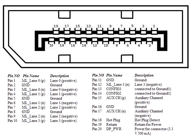
Well at least the 7 wires with good solder on picture 7 are the most important.
They are the two main lanes,AUX channel and the hotplug(violet wire)
To the other side there is the main power(Red wire) and GND, i don't see which wire is connected on pin 5
If all on the PCB is good then it should be only the shit male connector that doesn't make good contact with pins on graphic card.
Meanwhile I contacted Delock to explain the problem