Great to know. I have asked Polish distributor about availability and they told me it should hit the shelves around second week of September, price should be somewhere between $25 - $30. No available for preorder yet, but if I manage to get one I'm gonna post the results for sure.
Navigation
Install the app
How to install the app on iOS
Follow along with the video below to see how to install our site as a web app on your home screen.
Note: This feature may not be available in some browsers.
More options
You are using an out of date browser. It may not display this or other websites correctly.
You should upgrade or use an alternative browser.
You should upgrade or use an alternative browser.
24" Widescreen CRT (FW900) From Ebay arrived,Comments.
- Thread starter mathesar
- Start date
spacediver
2[H]4U
- Joined
- Mar 14, 2013
- Messages
- 2,715
I'm anxious to test one of these out too, primarily to see whether it can support 10 bit LUT adjustments (very important for gamma adjustment)
Can you explain how a 10 bit LUT can affect an 8 bit DAC?I'm anxious to test one of these out too, primarily to see whether it can support 10 bit LUT adjustments (very important for gamma adjustment)
I don't know about the quality, but there is a limit to the number of resolvable pixels you can put on the screen depending on the pixel pitch. If your screen is 19 inches wide, has 0.23 mm pixel pitch then there are about 2098 possible horizontal pixels. If your pixel clock is 340 MHz and your display allows 121 kHz horizontal refresh and requires a 2 µs horizontal sync, then the minimum pixels allowed per line (to make each pixel as wide as possible) is (340 M / 121 k) - (340 M * 2 µ) = 2130 pixels which is more than the pixel pitch will allow to be resolvable.I have a question for those who have bought the vcom converter,how is the video quality compared to the native DAC? (specify if with AMD or Nvidia)
Enhanced Interrogator
[H]ard|Gawd
- Joined
- Mar 23, 2013
- Messages
- 1,429
2130 pixels which is more than the pixel pitch will allow to be resolvable.
But higher pixel clocks allow you to run higher refresh rates too. So even below pixel pitch, there are benefits.
Chief Blur Buster
Owner of BlurBusters
- Joined
- Aug 18, 2017
- Messages
- 430
Also, at faster scan rates, the electron gun benefits from a higher-frequency RAMDAC -- the left/right edges of pixels can remain sharper rather than horizontally-analog-blurred.But higher pixel clocks allow you to run higher refresh rates too. So even below pixel pitch, there are benefits.
For some high-end CRTs, you really need overkill dotclock margin (roughly ~2-3x beyond pixel pitch) to fully max-out the sharpness of the left/right edge pixel boundaries on a CRT.
Assuming of course, the bandwidth of the CRT and electron gun focus isn't the limiting factor, and that the pixel/grille pitch is your main limiting factor.
You don't need to max-out the pixel clock in order to derive benefits. A 340 MHz RAMDAC can still produces a clearer picture at 170 MHz, than a 170 Mhz RAMDAC even with a monitor that is mathematically calculated to max-out at ~170 Mhz due to the monitor's dot pitch. This of course assumes your electron gun is well-focussed (fully maxing out the pitch of your monitor). The overkill simply sharpens the left/right edges of pixel boundaries -- very apparent of test patterns containing vertical lines.
It varies by monitor to monitor (Some have poor electronics where things just simply gets blurrier at higher refresh rates of the same resolution, for example -- no matter how good your RAMDAC is) but I've seen CRTs really shine with insane-dotclock RAMDACs being run at lower dotclocks. Under a magnifying glass, it can be the difference between "VHS-blurry-blended-pixels-look" versus "DVD-crisp-pixels-look" (imagine a DVD recording of a 320x240 JPEG, versus a VHS recording of a 320x240 JPEG -- the pixels will be squarer, steadier and crisper with less blurring into adjacent pixels)
If you're trying to adjust picture on an 8-bit picture, interim calculations need to stay at high accuracy.Can you explain how a 10 bit LUT can affect an 8 bit DAC?
Multiple intermediate pixel calculations (e.g. H.264 decompressing, gamma adjust, HDR downconversion to SDR, etc) can accumulate math rounding errors that results in more posterization / banding / blocky artifacts when finally slaughtered by an 8-bit DAC. Repeated 8-bit processing steps can effectively reduce the quality of an image to literally 6-bits-looking or 7-bits looking; showing unnecessarily-amplified blocky-artifacts in even high-bitrate videos and stuff like that.
So you really want to keep the graphics in a 10-bit workflow as long as possible, before it finally hits an 8-bit DAC (if that is unavoidable for you). It'll have less banding / blocky artifacts if it has only one 8-bit-related rounding error. Fewer accumulated rounding errors.
Last edited:
A higher pixel clock allows higher refresh rates only up to the maximum vertical or horizontal refresh rate. My calculation was for the minimum number of pixels per line at the maximum horizontal refresh rate. At that point, increasing the pixel clock without increasing the number of pixels per line would exceed the maximum horizontal refresh rate. At the horizontal refresh rate maximum, a higher pixel clock can only allow higher resolutions, until you reach the vertical refresh rate minimum.But higher pixel clocks allow you to run higher refresh rates too. So even below pixel pitch, there are benefits.
A faster DAC may have a faster rise/fall time. The ANX9847 has a rise/fall time (between 10% and 90% intensity) of 1100 pS. A 340 MHz pixel is 2941 pS. So the intensity of a black and white pattern like this:Also, at faster scan rates, the electron gun benefits from a higher-frequency RAMDAC -- the left/right edges of pixels can remain sharper rather than horizontally-analog-blurred.
For some high-end CRTs, you really need overkill dotclock margin (roughly ~2-3x beyond pixel pitch) to fully max-out the sharpness of the left/right edge pixel boundaries on a CRT.
Assuming of course, the bandwidth of the CRT and electron gun focus isn't the limiting factor, and that the pixel/grille pitch is your main limiting factor.
You don't need to max-out the pixel clock in order to derive benefits. A 340 MHz RAMDAC can still produces a clearer picture at 170 MHz, than a 170 Mhz RAMDAC even with a monitor that is mathematically calculated to max-out at ~170 Mhz due to the monitor's dot pitch. This of course assumes your electron gun is well-focussed (fully maxing out the pitch of your monitor). The overkill simply sharpens the left/right edges of pixel boundaries -- very apparent of test patterns containing vertical lines.
It varies by monitor to monitor (Some have poor electronics where things just simply gets blurrier at higher refresh rates of the same resolution, for example -- no matter how good your RAMDAC is) but I've seen CRTs really shine with insane-dotclock RAMDACs being run at lower dotclocks. Under a magnifying glass, it can be the difference between "VHS-blurry-blended-pixels-look" versus "DVD-crisp-pixels-look" (imagine a DVD recording of a 320x240 JPEG, versus a VHS recording of a 320x240 JPEG -- the pixels will be squarer, steadier and crisper with less blurring into adjacent pixels)
Code:
  __  __  __  __  __
__  __  __  __  __  __
Code:
   _   _   _   _   _
__/ \_/ \_/ \_/ \_/ \_Yes, 10 bit calculations are better than 8 bit calculations, but have nothing to do with the quality at the DAC stage (the adapter), after the calculations are done.If you're trying to adjust picture on an 8-bit picture, interim calculations need to stay at high accuracy.
Multiple intermediate pixel calculations (e.g. H.264 decompressing, gamma adjust, HDR downconversion to SDR, etc) can accumulate math rounding errors that results in more posterization / banding / blocky artifacts when finally slaughtered by an 8-bit DAC. Repeated 8-bit processing steps can effectively reduce the quality of an image to literally 6-bits-looking or 7-bits looking; showing unnecessarily-amplified blocky-artifacts in even high-bitrate videos and stuff like that.
So you really want to keep the graphics in a 10-bit workflow as long as possible, before it finally hits an 8-bit DAC (if that is unavoidable for you). It'll have less banding / blocky artifacts if it has only one 8-bit-related rounding error. Fewer accumulated rounding errors.
spacediver
2[H]4U
- Joined
- Mar 14, 2013
- Messages
- 2,715
Can you explain how a 10 bit LUT can affect an 8 bit DAC?
If it truly is an 8 bit DAC, then it will make no difference how precisely the LUT is specified (as you correctly point out). I'm desperately hoping somehow it'll allow true 10 bit precision in the same way that the DACs on the Nvidia cards do. That way, I can choose my 256 step luminance function from a palette of 1024 colors. The way I like to calibrate my CRTs requires that software step, and if it's only 8 bit, I can't do software calibration without crushing some of the 256 levels together.
If it turns out it's truly 8 bit (as the specs indicate), then I hope someone can put together a 10 bit version. Still, I do want to test it.
You can find a data sheet of the chip on a Chinese website. It definitely says 8 bit. Also, 30 bit color would decrease the maximum pixel clock from 360 MHz to 288 MHz. You would need a 4 lane or HBR3 adapter to go higher. I think there are many 10 bit DACs in the 165 to 180 MHz range which are good enough for 1920x1080p @ 60 Hz. They could be one lane or HBR, which would limit them to 144 MHz for 30 bit color.If it turns out it's truly 8 bit (as the specs indicate), then I hope someone can put together a 10 bit version. Still, I do want to test it.
The ADV7123 does 330 MHz, but I don't know of an adapter that uses it. The ADV7123 is just a DAC so a DisplayPort controller chip would also be required.
Chief Blur Buster
Owner of BlurBusters
- Joined
- Aug 18, 2017
- Messages
- 430
Good reply!A higher pixel clock allows higher refresh rates only up to the maximum vertical or horizontal refresh rate. My calculation was for the minimum number of pixels per line at the maximum horizontal refresh rate. At that point, increasing the pixel clock without increasing the number of pixels per line would exceed the maximum horizontal refresh rate. At the horizontal refresh rate maximum, a higher pixel clock can only allow higher resolutions, until you reach the vertical refresh rate minimum.
Also, we have a distinction between the manufacturer "maximum" and the electronics "real maximum".
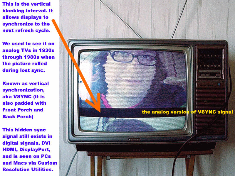
As one trick some CRT users do -- unofficially, with some monitors, you can increase refresh rate by going interlaced or tweaking with VBI's via CRU. It does help if you use a Custom Resolution Utility (ToastyX/NVIDIA/AMD) to increase the vertical blanking interval (VBI) to match the VBI time of a lower refresh rate. (Basically a high Hz with a very large VBI to help reduce strain and to fix compressed-image-height symptom on some CRTs that occurs at high refresh rates). That way, the same number of microseconds is maintained in moving the electron gun back to the beginning of a new refresh cycle. A 110Hz progressive resolution might easily go 170Hz when interlaced, for example, even though the manufacturer specified a 110 Hz maximum for that resolution. For some monitors, it isn't even working harder at all and no temperature change (usually good, really high-end CRTs will be well overbuilt, horizontal scanrate is never exceeded, only more frequent vertical deflections to begin a new refesh cycle, with only minor compressed-image-height behavior). While for others less well designed, they might have undue strain (e.g. insufficient time to recharge capacitors for the next major vertical deflection triggered upon VSYNC signal, more local heating from more frequent vertical deflections, etc). A desk fan pointed at CRT's vents during warm weather is prudent when pushing a CRT's limits. Assuming the monitor doesn't have an electronics blank-out for this type of "out-of-manufacturer-recommendation" signals.
Last edited:
Enhanced Interrogator
[H]ard|Gawd
- Joined
- Mar 23, 2013
- Messages
- 1,429
A higher pixel clock allows higher refresh rates only up to the maximum vertical or horizontal refresh rate. My calculation was for the minimum number of pixels per line at the maximum horizontal refresh rate. At that point, increasing the pixel clock without increasing the number of pixels per line would exceed the maximum horizontal refresh rate. At the horizontal refresh rate maximum, a higher pixel clock can only allow higher resolutions, until you reach the vertical refresh rate minimum.
I guess my point is that 21" monitors, and even 19" in some cases, have horizontal scan ranges that exceed what this Analogix adapter could theoretically feed them. Like my LaCie monitor can scan 1920x1440@90hz. That's around 395mHz pixel clock.
And something else that needs to be said: For PC games, running high resolutions that are beyond your monitor's pixel pitch still gives a noticeable improvement in image quality. It's like pure, analog super-sampling versus the digital form in something like Nvidia's DSR
spacediver
2[H]4U
- Joined
- Mar 14, 2013
- Messages
- 2,715
You can find a data sheet of the chip on a Chinese website. It definitely says 8 bit. Also, 30 bit color would decrease the maximum pixel clock from 360 MHz to 288 MHz. You would need a 4 lane or HBR3 adapter to go higher. I think there are many 10 bit DACs in the 165 to 180 MHz range which are good enough for 1920x1080p @ 60 Hz. They could be one lane or HBR, which would limit them to 144 MHz for 30 bit color.
The ADV7123 does 330 MHz, but I don't know of an adapter that uses it. The ADV7123 is just a DAC so a DisplayPort controller chip would also be required.
Interesting, just looked up that ADV7123 and it looks like it would be perfect. Would it in principle be possible to cannibalize the Declock adaptor and replace the ANX9847 DAC with an ADV7123 DAC?
Not a single chance.Different chips almost never have the same functions on the same pins even if they have the same amount of pins and the same purpose. On the top of that, an extra chip would be required (the ADV7123 converts a digital signal into analog, but it doesn't "understand" the code of a displayport transmission, I'm not sure it understands VGA either BTW, just translates 1 and 0 into voltage variations).Interesting, just looked up that ADV7123 and it looks like it would be perfect. Would it in principle be possible to cannibalize the Declock adaptor and replace the ANX9847 DAC with an ADV7123 DAC?
In other words, entirely redesigning the adapter's PCB would be required.
spacediver
2[H]4U
- Joined
- Mar 14, 2013
- Messages
- 2,715
and even if you could get a 10 bit displayport-VGA adaptor, there's no guarantee the video card will respect 10 bit LUT adjustments.
So with your example, you can gain 55% temporal resolution by sacrificing 50% spatial resolution by using interlaced. That's neat.As one trick some CRT users do -- unofficially, with some monitors, you can increase refresh rate by going interlaced or tweaking with VBI's via CRU.
My point is that there is a way you can justify accepting that 330 or 340 MHz is not too shabby in most cases, though we know it could be better with a 4 lane HBR2 adapter. A 4 lane adapter cannot be used with a USB-C dock though, but that's the same problem you get when you want to use 4K@60Hz DisplayPort or HDMI from a USB-C dock (you can't).I guess my point is that 21" monitors, and even 19" in some cases, have horizontal scan ranges that exceed what this Analogix adapter could theoretically feed them. Like my LaCie monitor can scan 1920x1440@90hz. That's around 395mHz pixel clock.
And something else that needs to be said: For PC games, running high resolutions that are beyond your monitor's pixel pitch still gives a noticeable improvement in image quality. It's like pure, analog super-sampling versus the digital form in something like Nvidia's DSR
About quality, I forgot to mention the transition time (or overshoot / undershoot and overshoot / undershoot settling time) as a factor (similar/related to rise/fall times). Figure 2 Timing Diagram of the ADV7123 data sheet shows what that's about. It's a ripple that happens after the rise or fall of a transition. Although the ADV7123 has a faster rise/fall time (1000 pS) than the ANX9847 (1100 pS), it has a 15000 pS transition time (settling to 2% of final value). The transition time for the ANX9847 is specified as the time it takes to settle within 5% of final value, so it's only 500 pS but it's not fair to compare those times.
The ANX9847 is not just a DAC. It's an all in one solution containing both a DisplayPort receiver and a VGA transmitter. It's a 48 pin chip. First the DisplayPort receiver would need to be changed to accept 30 bit color, then you would need to add 30 pins for the 30 bit color output.Interesting, just looked up that ADV7123 and it looks like it would be perfect. Would it in principle be possible to cannibalize the Declock adaptor and replace the ANX9847 DAC with an ADV7123 DAC?
I think the Megachips MCDP2900 is interesting as a DisplayPort receiver. http://www.megachips.com/products/Data_Brief/MCDP2900_Databrief.pdf. Then you just need to decode or deserialize the HDMI output. Bonus points if you can extract audio too. The STDP4020 might be more direct but it is less capable.
spacediver
2[H]4U
- Joined
- Mar 14, 2013
- Messages
- 2,715
Thanks joevt, appreciate the clarification and awesome info ")
Where are you located?
Anyone interested on a BRAND NEW IN BOX (YES... BRAND NEW ZERO (0) HOURS OF USE) GDM-FW900, which I unboxed on the 21st. to run basic tests, please let me know via PM... First come, first serve...
Sincerely,
Unkle Vito!
danny_discus
Gawd
- Joined
- Dec 13, 2006
- Messages
- 612
He is out of Los Angeles, CA
LAGRUNAUER
Gawd
- Joined
- Dec 7, 2006
- Messages
- 745
That is correct! We operate in Los Angeles, CA...
LAGRUNAUER
Gawd
- Joined
- Dec 7, 2006
- Messages
- 745
We are getting six (6) GDM-F520 possibly within the next 15 days. This is the little brother of the GDM-FW900. Anyone interested, PM me... First come, first served!
Sincerely,
Unkle Vito!
Sincerely,
Unkle Vito!
If it turns out it's truly 8 bit (as the specs indicate), then I hope someone can put together a 10 bit version. Still, I do want to test it.
The only converters i know that can do 10 bit are HDFURY,but pixel clock is 225 MHz and i don't know how much it can do (HDMI 1.4 10 bit is 272 MHz?)
The ADV7123 does 330 MHz, but I don't know of an adapter that uses it.
I remember when i was looking for this and the TDA8777,i didn't find anything and the big problem is to find someone for the custom circuit with others chip,there aren't reference design.
A 4 lane adapter cannot be used with a USB-C dock though, but that's the same problem you get when you want to use 4K@60Hz DisplayPort or HDMI from a USB-C dock (you can't).
There are converters for USB-C to HDMI 2.0 and the chip inside uses 4 lanes,you mean that current hardware with USB-C output use only 2 lanes because the other 2 are connected to usb?
Graphic cards with USB-C connector will resolve that.
New Delock's USB-C to VGA are already available, it should be days till there are Displayport to VGA adapters.
USB-C version is on sale from April,for the other look here:
https://geizhals.eu/1186365303
With the passing of days there will be more stores.
Last edited:
jbltecnicspro
[H]F Junkie
- Joined
- Aug 18, 2006
- Messages
- 9,541
Sad to say - putting my CRT's up for sale. I have a FS/FT thread but I won't link it - should be pretty obvious as to which thread is mine. Basically - living situation is changing soon, and I need to sell them off. PM me for more details and check out the thread. It was a fun run and good times were had, but I have to be moving on.
It was a fun run and good times were had, but I have to be moving on.Bought my Delock from a Dutch store: https://www.hardwarewebwinkel.nl/ka...ck-adapter-displayport-12-m-groter-vga-f.htmlGood news,Delock sent me a DP to VGA sample converter with the ANX9847 chipset and i tested it.
After loading the system and without any EDID override you can set 1920x1440 85Hz
...
It doesn't output a stable image at pixelclocks higher than ~170MHz for me. 1920x1080@60 works fine, at 1920x1080@70 it starts losing it's vertical sync continuously and at 1920x1200@85 it can't even show a synced image anymore. I have used EDID (EDID from FW900 is passed through to Displayport connector) and been playing with custom resolutions.
I have connected the adapter to a Nvidia GTX 970 GPU, currently there is no other Displayport 1.2 GPU here to test with. Disappointing, I would almost crack open the adapter to see if it has a true ANX9847 inside lol.
EDIT: doesn't seem to be a (pure) pixel-clock limitation. 1366x768@85 (~125MHz) isn't stable, but 1280x1024@85 (~160MHZ) is.
Last edited:
bramabul5353
Weaksauce
- Joined
- Dec 15, 2014
- Messages
- 110
Brand New D-Board and Flyback Transformer for sale. PM me
Chief Blur Buster
Owner of BlurBusters
- Joined
- Aug 18, 2017
- Messages
- 430
Have you tried slightly increasing the blanking interval? You want to use CRT timings rather than digital timings, sometimes that helps some adaptors (not all). This helps prevent the loss of VSYNC.It doesn't output a stable image at pixelclocks higher than ~170MHz for me. 1920x1080@60 works fine, at 1920x1080@70 it starts losing it's vertical sync continuously and at 1920x1200@85 it can't even show a synced image anymore. I have used EDID (EDID from FW900 is passed through to Displayport connector) and been playing with custom resolutions.
Sometimes ToastyX does a better job of creating CRT-compatible blanking intervals than NVIDIA Custom Resolution or Radeon Catalyst Control Center.
When you have no EDID data available, you have to manually create override resolutions with the correct large blanking intervals that is friendly to your CRT. When using a higher pixel clock, try using the excess pixel clock in larger blanking intervals (both horizontal and vertical, especially vertical). Helps a huge deal.
When you're inside ToastyX Custom Resolution Utility, do NOT use the "LCD Standard", but select the "CRT standard" or "CVT formula" option in the CRU to properly calculate the size of the blanking interval needed for your CRT modes. This is often necessary to do manually, when EDID data is missing, and often solves rolling-picture problems. This automatically uses the correct formula, and in a way that isn't overriden by GPU scaling, etc. May not always help, but give it a try.
Download: https://www.monitortests.com/forum/Thread-Custom-Resolution-Utility-CRU
Last edited:
Bought my Delock from a Dutch store: https://www.hardwarewebwinkel.nl/ka...ck-adapter-displayport-12-m-groter-vga-f.html
It doesn't output a stable image at pixelclocks higher than ~170MHz for me. 1920x1080@60 works fine, at 1920x1080@70 it starts losing it's vertical sync continuously and at 1920x1200@85 it can't even show a synced image anymore. I have used EDID (EDID from FW900 is passed through to Displayport connector) and been playing with custom resolutions.
I have connected the adapter to a Nvidia GTX 970 GPU, currently there is no other Displayport 1.2 GPU here to test with. Disappointing, I would almost crack open the adapter to see if it has a true ANX9847 inside lol.
EDIT: doesn't seem to be a (pure) pixel-clock limitation. 1366x768@85 (~125MHz) isn't stable, but 1280x1024@85 (~160MHZ) is.
It seems that for some reason your video card doesn't output in HBR2 mode (DP 1.2)
I had the same result when i tested the adapter on a AMD 5850 with DP 1.1a
Practically the adapter has a DP lane configuration based on the bandwidth,inside the firmware to reduce power consumption.
Looking the datasheet:
Up to 85-90 MHz it uses one RBR or HBR lane
After 85-90 MHz it uses one HBR2 lane
After 162 it uses 2 HBR2 lanes
These settings are not precise,so the switching can happen before or after these ranges
This is the problem,after 85-90 MHz GPU try to switch to 2 HBR lanes because one isn't sufficient,but adapter switch to one HBR2 lane which isn't present (so it go to one HBR)
I think that these switching cause all that fucking out of sync
In your case:
1920x1080 60 Hz is fine because adapter set two HBR2 lanes and even HBR is sufficient
1920x1080 70 Hz isn't stable because is over 180 MHz (over HBR capacity)
1366x768 85 Hz isn't stable because is between 90 and 160 MHz
1280x1024 85 Hz is fine because adapter set two HBR2 lanes and even HBR is sufficient
I hope it's not a problem inside the adapter (bad cable or bad connections on PCB side) that prevents the adapter to work correctly at HBR2 mode.
If this is confirmed by others users and with others GPU i will immediately contact Delock
Just for informations:
one RBR lane 54 MHz
one HBR lane 90 MHz
one HBR2 lane 180 Mhz
Try this:
set 1024x768 75 Hz (it should be stable)
set 1024x768 100 Hz (not stable)
set 1024x768 140 Hz (it should be stable)
Try searching the web to see if there are problems with your video card and displayport connection.
Maybe with another bios or driver you can resolve it
If the adapter works ok and you can't resolve the problem with DP,an adapter HDMI to DP 1.2 can be usefull (but it should be very good)
Did you buy the adapter to use it with the 970 or just to test it before changing the card?
Do you have the ability to test it to another card?
What is the exact model of your video card?
EDIT
I did a quick search and it seems that some GTX 900 series are plagued by DP problems,especially with 1.2 mode,but there are solutions.
Last edited:
Welcome by the way, all the information in this thread is of great help. I'm running two FW900s for games mostly, one was having focus losing problems, but lately it's not coming back. spacediver's WPB guide looks super, now since I bought that DTP-94 colorimeter I hope to calibrate them soon Especially since CRT black levels are what make dark games like the newest Doom shine on the screen and OLED high-frequency monitors are taking looong to become available.
And you are the one testing FreeSync on CRTs, I saw your thread over at Blur Busters I'm very interested in that part and that's why I hope the Delock adapter is compatible for it, do you know this? Would be so awesome to have FreeSync on the FW900 CRT.
The status right now:
- All resolutions up to 180MHz are fine now
- 180MHz till 340MHz outputs the correct resolution with pixel-snow and an unstable image. With 341MHz and higher there is no output at all, like you found out yourself.
Also it doesn't really matter if it's a 180MHz or 340MHz resolution, they share the same amount of instability in terms of losing sync and pixel-snow. At least it means the GPU is outputting 2-lane HBR2, but it looks like the DP data signals are not stable in that mode. Still can be either the Delock circuit design or connections which doesn't handle high bandwidth signals properly, but I hope it's the GPU.
I'm gonna return my adapter for a new one I guess, after that I have to get access to another DP1.2 GPU.
Especially since CRT black levels are what make dark games like the newest Doom shine on the screen and OLED high-frequency monitors are taking looong to become available.The Delock adapter passes through all the FW900 EDID data and I've been manually testing CRT timings using ToastyX's CRU program. Right now only less blanking works better because the pixelclock stays <180MHz and I can use a higher effective resolution that way. I noticed Nvidia's Custom Resolution can be tricky since sometimes it only scales to another available resolution instead of actually outputting a new custom resolution.Have you tried slightly increasing the blanking interval? You want to use CRT timings rather than digital timings, sometimes that helps some adaptors (not all).
And you are the one testing FreeSync on CRTs, I saw your thread over at Blur Busters
I'm very interested in that part and that's why I hope the Delock adapter is compatible for it, do you know this? Would be so awesome to have FreeSync on the FW900 CRT.I'm definitely having DP (connection) problems. At one point no resolution above 180MHz was outputting anymore. Then I touched the DP plug going into the GPU a little and it was 'working' again. This DP male plug doesn't make a reliable and tight fit I'm afraid, at least not with this GPU port. Nothing happened to the GPU port btw.It seems that for some reason your video card doesn't output in HBR2 mode (DP 1.2)
I had the same result when i tested the adapter on a AMD 5850 with DP 1.1a
The status right now:
- All resolutions up to 180MHz are fine now
- 180MHz till 340MHz outputs the correct resolution with pixel-snow and an unstable image. With 341MHz and higher there is no output at all, like you found out yourself.
Also it doesn't really matter if it's a 180MHz or 340MHz resolution, they share the same amount of instability in terms of losing sync and pixel-snow. At least it means the GPU is outputting 2-lane HBR2, but it looks like the DP data signals are not stable in that mode. Still can be either the Delock circuit design or connections which doesn't handle high bandwidth signals properly, but I hope it's the GPU.
I'm gonna return my adapter for a new one I guess, after that I have to get access to another DP1.2 GPU.
Last edited:
Chief Blur Buster
Owner of BlurBusters
- Joined
- Aug 18, 2017
- Messages
- 430
Blah! That's bad news.180MHz till 340MHz outputs the correct resolution with pixel-snow and an unstable image
Hope a replacement adaptor works. It's theoretically possible that a thicker/shorter DisplayPort cable could push things a bit better, as the adaptor might be operating at its weak-signal tolerances. Cable far away from power cabling and transformers/boxes, new high-spec DisplayPort cable (even one rated for higher bandwidth), etc -- may make up for DisplayPort flakiness that's the adaptor's fault. However, this may not help and I think you probably already covered this base (I bet...).
And you are the one testing FreeSync on CRTs, I saw your thread over at Blur Busters
Correct. FW900 FreeSync is the purpose of the upcoming Blur Busters article.
Much more FreeSync successes have occured since I posted that thread. But no tests yet on the famous CRTs yet, and I want to change that...
However, I plan to use HDMI + ToastyX force FreeSync over HDMI. We already now know FreeSync HDMI is easier than FreeSync DisplayPort when it comes to CRT testing. HDMI-to-analog is much more unfiltered (variable-size-VBI-preservation for FreeSync! Critical!) and direct than DisplayPort micropackets, especially since DisplayPort adaptors have a mandatory microbuffer to de-jitter DisplayPort micropacketization. VGA-to-HDMI is a simpler 1:1 conversion from digital to analog and vice versa, and much more likely to preserve the custom variable-length blanking intervals.
DisplayPort is total gtarbage for testing analog FreeSync as a result, as I prefer a direct-to-metal 1:1 digital-analog conversion of Custom Resolution Utility timings, and that's much easier to do with DVI-VGA and HDMI-VGA. So I've found older digital standards much more reliable in preserving the signalling that FreeSync requires, and it's more likely to survive a 1:1 digital-analog conversion.
FreeSync is just simply variable-height blanking intervals, and they are often compatible with "good" MultiSync CRTs.
FreeSync simply varies the height of that rolling black bar.
Conceptually, that's all FreeSync is.... which is why FreeSync is CRT compatible. FreeSync maintains horizontal scanrate, same number of scanlines per second, dotclock is unchanged. It just only varies the number of black scanlines in the "black VSYNC bar" separating the refresh cycles (via realtime modulation of Vertical Back Porch in the VBI). Several MultiSync CRTs successfully tolerate this (not all; some of them blank out once refresh rate changes too much).
The magic is that horizontal sync and dotclock is unchanged during FreeSync, and FreeSync / VESA Adaptive-Sync / HDMI Game Mode VRR -- all of them simply vary the height-thickness of that rolling VHOLD black bar between refresh cycles -- to temporally displace the next refresh cycle. It's surprisingly simple how FreeSync works, and amazing that it wasn't done twenty years ago.
Nothing prevents CRTs from inherently being variable refresh rate, as long as the electronics are fast at synchronizing to continually-changing VBI. Vector CRTs are always variable refresh rate, remember those old Star Wars arcade machines started to flicker more crazy when there were more vectors? That's because the refresh rate is varying (in year 1982!) as you play Star Wars on the vector CRT. Likewise, if you had a Vectrex machine, same thing...
The important thing is that to get CRT FreeSync working properly (maximum success reports), is direct 1:1 digital-analog conversion of the FreeSync signal -- and I've found that much easier to do with older digital standards -- ala HDMI/DVI signalling.
DisplayPort FreeSync may work on CRT, but the success rate is extremely abysmal for that. If you can get 340MHz FreeSync surviving a digital-analog conversion, I want to hear from you.
CRT FreeSync succeeded on other CRTs, but I would love to be the first to write an article about FreeSync tests on the famous FW900 CRT.
Since wide refresh rate range is desired with FreeSync -- meaning high top refresh rate -- meaning high vertical scanrate -- one can reduce resolution (e.g. 1280x720) in order to increase the CRT FreeSync range on a FW900 CRT. Since we may be able to be slamming against a refresh rate limitation before a dotclock limitation, it is doable with a lower-spec HDMI adaptor, since we may run out of refresh rate room than run out of dotclock room -- so we can get by with a bigger FreeSync range on a lower-spec adaptor, simply by focussing on a slightly lower resolution for now.
The easiest tools for FreeSync tests is the "dumbest" digital-analog adaptor (essentially 1:1 unfiltered conversion, no "EDID modification", no transcoding, no processing, no micropacket complexity) for the most reliable/easiest FreeSync preservation in a HDMI-to-VGA adaptor. Then ToastyX to force FreeSync over HDMI. Then playing with VRR ranges until FreeSync works with fewest glitches.
Since it's so darned difficult for me to find a FW900 CRT (or similar) to borrow/rent/buy/visit -- I'm willing to pay a freelancer to do FW900 CRT FreeSync tests instead, for the Blur Busters article. (I'd obviously credit/link this forum thread as the definitive source of FW900 community information). If one of you have written articles, we'd love to have someone help out in this FW900 CRT FreeSync experiment.
I already have the necessary adaptor, and access to lesser mortals of CRTs, but FW900 is certainly the CRT of lore (As is a few others, such as Nokia 445pro). I want to find the "most desirable CRT that ends-up-being-apparently-FreeSync-compatible".
It is something I have been wanting to do for a very long time -- test FreeSync on the most famous widescreen CRT monitor. I wish FW900's were easier to find in Toronto, Canada!
Last edited:
I'm definitely having DP (connection) problems. At one point no resolution above 180MHz was outputting anymore. Then I touched the DP plug going into the GPU a little and it was 'working' again. This DP male plug doesn't make a reliable and tight fit I'm afraid, at least not with this GPU port. Nothing happened to the GPU port btw.
The status right now:
- All resolutions up to 180MHz are fine now
- 180MHz till 340MHz outputs the correct resolution with pixel-snow and an unstable image. With 341MHz and higher there is no output at all, like you found out yourself.
Also it doesn't really matter if it's a 180MHz or 340MHz resolution, they share the same amount of instability in terms of losing sync and pixel-snow. At least it means the GPU is outputting 2-lane HBR2, but it looks like the DP data signals are not stable in that mode. Still can be either the Delock circuit design or connections which doesn't handle high bandwidth signals properly, but I hope it's the GPU.
I'm gonna return my adapter for a new one I guess, after that I have to get access to another DP1.2 GPU.
So the card output HBR2 mode but unstable,users with 970 and 980 had the same problem with monitors that works correctly with DP 1.1 but totally unstable with DP 1.2 and this with certified VESA cables.
Have you checked if the connector on the card is clean? (no dust and so on)
If the problem is the cable of the adapter maybe a Displayport male to female adapter can help.
Is there someone else who ordered the adapter?
Conceptually, that's all FreeSync is.... which is why FreeSync is CRT compatible. FreeSync maintains horizontal scanrate, but varies the number of black scanlines in the "black VSYNC bar" separating the refresh cycles. Several MultiSync CRTs successfully tolerate this (not all; some of them blank out once refresh rate changes too much).
The magic is that horizontal sync is unchanged during FreeSync, and FreeSync / VESA Adaptive-Sync / HDMI Game Mode VRR -- all of them simply vary the height-thickness of that rolling VHOLD black bar between refresh cycles -- to temporally displace the next refresh cycle. It's surprisingly simple how FreeSync works, and amazing that it wasn't done twenty years ago.
Nothing prevents CRTs from inherently being variable refresh rate, as long as the electronics are fast at synchronizing to continually-changing VBI. Vector CRTs are always variable refresh rate, remember those old Star Wars arcade machines started to flicker more crazy when there were more vectors? That's because the refresh rate is varying (in year 1982!) as you play Star Wars on the vector CRT. Likewise, if you had a Vectrex machine, same thing...
The important thing is that to get CRT FreeSync working properly (maximum success reports), is direct 1:1 digital-analog conversion of the FreeSync signal -- and I've found that much easier to do with older digital standards -- ala HDMI/DVI signalling.
DisplayPort FreeSync may work on CRT, but the success rate is extremely abysmal for that. If you can get 340MHz FreeSync surviving a digital-analog conversion, I want to hear from you.
The problem is that if the vertical refresh changes,the monitor switch to the new mode even if the horizontal sync is the same.
I just tested a resolution:
1440x1050 standard CVT timings 93.929 Khz 85.003 Hz
and
1440x1050 manual increased vertical blanking 93.929 Khz 80.007 Hz
When i change from 85 to 80 the monitor switch as a normal resolution change
Is my test correct or it work in another way?
Chief Blur Buster
Owner of BlurBusters
- Joined
- Aug 18, 2017
- Messages
- 430
Four possible outcomes:The problem is that if the vertical refresh changes,the monitor switch to the new mode even if the horizontal sync is the same.
I just tested a resolution:
1440x1050 standard CVT timings 93.929 Khz 85.003 Hz
and
1440x1050 manual increased vertical blanking 93.929 Khz 80.007 Hz
When i change from 85 to 80 the monitor switch as a normal resolution change
Is my test correct or it work in another way?
1. Traditional resolution changes are often unsynchronized
They are sometimes interrupted into the middle of a refresh cycle, triggering a monitor into a mode change. Traditional resolution changes may also blank the signal (like a tiny, brief sleep). There is no guarantee how the mode change is seamlessly spliced into the cable bitstream. The new VBI must be perfectly seamlessly spliced between refresh cycles. Only FreeSync can guarantee perfectly synchronized equivalent of a "subtle mode change" at the cable signal level. Also, adaptors must not interfere with mode changes (unwanted scan conversions or timings modifications).
CRT FreeSync compatibility not ruled out
2. Three different ways to vary the height of VBI.
The VBI black bar is a grand total (Front Porch + Sync + Back Porch) in number of scan lines. In an analog signal, porches are slightly below NTSC black while Sync is often much below NTSC black (far below the reference voltage of active-picture black). Porches act as temporal padding between active image and the sync signal, for synchronization electronics. FreeSync only changes one number of the three, and leaves the other two number untouched. This can bypass blankout electronics.
CRT FreeSync compatibility not ruled out
UPDATE: I just talked to Zisworks who confirmed: FreeSync modulates only the Vertical Back Porch. Dotclock constant, *all* horizontal porches/sync constant, vertical sync constant, vertical front porch constant. Only Vertical Back Porch is dynamically modulated on-the-fly.
3. Arbitrary electronic blankout trigger thresholds may be too strict.
It is possible that monitor safeguards electronically even on this. Monitor blank-out is an unwanted side effect that affects newer MultiSync monitors. FreeSync may be easier on the older GDM-W900 than the newer FW900, since you do not want the monitor electronics to be fussy and "play bad cop" doing unnecessary blankouts on perfectly-synchronized VBI-size-change. Otherwise, monitor blank-out electronics (whether linear-electronics-driven blankout or a firmware triggered blankout) makes FreeSync impossible on a specific true MultiSync CRT.
CRT FreeSync is SOL for specific monitor model until blankout is overriden (open up monitor, or modify firmware, etc)
4. Slew rate of refresh rate changes
Some blankout electronics ignores perfectly synchronized FreeSync changes. Also, for some CRT monitors, slew-rate can be important for CRT FreeSync (actual gameplay with gently modulating framerates may not cause blankout, but bringing up a menu, or sudden framerate stall might). When playing a game, turning from a wall to a complex scene, often gives you gradually increasing/decreasing framerate (= refreshrate). This can be far below the threshold of a specific CRT monitor's arbitrary firmware-hardcoded mode-change electronic blankout trigger. In addition, reducing FreeSync range slightly (10%) also can fix slew-rate-induced blankouts on some CRTs
CRT FreeSync compatibility not ruled out
TL;DR Rudimentary refresh-rate change tests do not always confirm CRT FreeSync incompatibility. Actual Freesync must be forced (via ToastyX force-HDMI trick) into the CRT, with various range tests, to confirm compatibility with seamless variable refresh rate...
Last edited:
ilovemyfw900
n00b
- Joined
- Aug 11, 2015
- Messages
- 5
Brand New D-Board and Flyback Transformer for sale. PM me
Hi could you please let me know how much? I can't seem to PM you on the forum - I am missing the option or somethin? Thanks!
2. The VBI black bar is a grand total (Front Porch + Sync + Back Porch) in number of scan lines. In an analog signal, porches are slightly below NTSC black while Sync is often much below NTSC black (far below the reference voltage of active-picture black). Porches act as temporal padding between active image and the sync signal, for synchronization electronics. FreeSync only changes one number of the three, and leaves the other two number untouched. This can bypass blankout electronics.
CRT FreeSync compatibility not ruled out
I changed only blanking total,which change only back porch with CRU,i don't think the other two are useful for freesync,they are too small (1 to 3 lines for GTF and 3 to 10 with CVT)
In this forum there are users with HDMI to VGA converters who can help you,i don't have one.
Chief Blur Buster
Owner of BlurBusters
- Joined
- Aug 18, 2017
- Messages
- 430
While I think it affects only sync -- The smallness of number is irrelevant at the top end of FreeSync range --I changed only blanking total,which change only back porch with CRU,i don't think the other two are useful for freesync,they are too small (1 to 3 lines for GTF and 3 to 10 with CVT)
The smallness of the number does not matter at the top end of FreeSync range. Reducing refresh rate in FreeSync always increases one number. (I need to confirm which). So originating smallness does not matter as long as the monitor likes it.
In ToastyX, you create the highest Hz, then force it over HDMI. Configure the FreeSync range. FreeSync/VESA Adaptive-Sync just increases one number to reduce Hz.
While I think it affects only sync -- The smallness of number is irrelevant at the top end of FreeSync range --
The smallness of the number does not matter at the top end of FreeSync range. Reducing refresh rate in FreeSync always increases one number. (I need to confirm which). So originating smallness does not matter as long as the monitor likes it.
In ToastyX, you create the highest Hz, then force it over HDMI. Configure the FreeSync range. FreeSync/VESA Adaptive-Sync just increases one number to reduce Hz.
Yes i forgot that actually i only increase the lines,but increased sync width can be a problem on a CRT (position of the image?)
Did you see my reply:
https://hardforum.com/threads/24-wi...ived-comments.952788/page-378#post-1043178486
What do you think about it?
During blanking the monitor cools down?
So reducing it reduce the cooling times?
This is what VESA says:
Horizontal blanking duty cycle has a great impact on the system design, particularly as there are many opposing
requirements. Making blanking time long, for instance, has both advantages and disadvantages:
Advantages:
• Lower cost, lower power dissipation horizontal scan/CRT yoke design at high frequencies
• More time for video RAM update during blanking interval
Disadvantages:
• Higher power dissipation horizontal scan/CRT yoke design at low frequencies
• Higher pixel clock operation, more expensive graphics chip sets, RAM, etc.
• Higher video rate and amplitude, requiring expensive, high power dissipation video amplifiers
• More RFI (radio frequency interference)
• Lower brightness/higher instantaneous CRT drive requirements, giving poor spotsize, focus, etc.
So reducing it is the opposite?
Last edited:
Have you checked if the connector on the card is clean? (no dust and so on)
Was planning to clean the GPU's DP-port with IPA cleaning fluid today and it works much better now!! At the same time I used a bit more force to connect the DP connector and it feels physically more tightened. The first 5 minutes the image was perfectly stable and now it starts rolling vertically again. Not so bad as before so I'm gonna check if the metal of my PC-case (to which the PCI-cards are attached) is physically obstructing the DP-plug of going all the way in. While typing this the image is getting more unstable, but no pixel-snow.Well done,so the problem is probably only the card connector.
And yea,the fucking metal case which caused me problems in the past
Try to clean with cleaning fluid the adapter connector as well
Last edited:
Chief Blur Buster
Owner of BlurBusters
- Joined
- Aug 18, 2017
- Messages
- 430
Changing vertical settings can affect image position and image size. It's very CRT dependant, and this behaves very differently (Front Porch vs Sync vs Back Porch) on different CRTs.Yes i forgot that actually i only increase the lines,but increased sync can be a problem on a CRT (position of the image?)
FreeSync has a completely unmodified dotclock + completely unmodified horizontals throughout its entire refresh rate range, and some monitors key on the blanking interval, keeping picture height practically unmodified. On good CRTs it is only tiny shifting (millimeters, max) throughout the FreeSync range. On other CRTs, picture will shift really badly. Trial-and-error. Luck-of-the-draw.
Now, another picture side effect: Flicker will vary on the fly, but not objectionably so -- if you've played Star Wars 1982 at the arcade, that flicker-modulation is sorta like that (vector CRTs are variable refresh rate). What happens is you see stutterless frame rate changes, as frame rate changes are stutterless. Change between, say 75fps -> 78fps occurs without any stutters, which is the beauty of FreeSync. Zero motion blur + zero stutters during fluctuating frame rates is why CRT FreeSync can be beautiful, when it works properly.
Forcing FreeSync on a CRT is considered out-of-ordinary operation for an ordinary CRT. Manufacturers never intended a raster multisync CRT to be subject to continuously changing refresh rates -- seeing 1980s multisync CRTs successfully do FreeSync is probably not something the manufacturer anticipated back then.Did you see my reply:
https://hardforum.com/threads/24-wi...ived-comments.952788/page-378#post-1043178486
What do you think about it?
Manufacturer recommendations won't be useful in helping calibrate FreeSync, except to define parameters at the highest FreeSync Hz.
The good news is it's a comfortable downhill coast from there, specs-wise. Increasing blanking interval actually improves cooldown. Thusly, most CRT electronics tolerate FreeSync being forced upon it. The addition of FreeSync usually simply has a safety-margin-increasing effect on most parameters (longer vertical blanking interval = more time = more time for vertical deflector cool down before next deflection).
Actually, no.During blanking the monitor cools down?
So reducing it reduce the cooling times?
With BLANKING interval = bigger number = longer = more time = good.
Increasing a blanking = longer pause between refresh cycles
= more cooldown time between refresh cycles (for vertical blanking)
= more cooldown time between scan lines (for horizontal blanking)
But horizontal is irrelevant for FreeSync because horizontal scanrate is unchanged in FreeSync versus non-FreeSync operation. The amount of horizontal blanking time is unchanged. The pause between scan lines is unchanged regardless whether you turn ON/OFF FreeSync for a specific resolution. The horizontal timings are completely unaffected.
The number of scanlines per second remains exactly the same at all times (even while refresh rate varies), it's a precise metronome to the nanosecond. No matter how much FreeSync or AdaptiveSync varies, the dotclock is constant, the horizontals is constant, the number of scanlines per second is constant, the time between scanlines is constant. That never changes during FreeSync. You choose one number, and stick with it. There's nothing stopping an arbitrarily small or arbitrarily large horizontal blanking interval from working with FreeSync; it just remains merrily constant and untouched as the refresh rate varies.
That's how precisely FreeSync synchronously modulates refresh rates, via precision addition/removal of VBI scanlines realtime on-the-fly (to pad time between refresh cycles). The horizontal parameters/timings/etc doesn't change by a single nanosecond during FreeSync! Such precisely-timed realtime addition/removal of scanlines in VBI is the hallmark of FreeSync, and it often can slip through some CRT monitors' blankout electronics untouched. It's monitor dependant how sensitive a CRT monitor blanks out during mode changes.
That said, mathematical interactions is important when creating the baseline FreeSync mode (it's simply creating the highest Hz mode -- the top end of your FreeSync range). If you're beginning with a larger horizontal blanking intervals for horizontal, your dotclock room might run out before you can use the monitor's top refresh rate. So just go with your manufacturer recommendation + a safety margin, preferably stick to VESA or even pad it to a number "bigger and safer than VESA" if you are so worried about pushing horizontal limits.
Increasing dotclock doesn't universally always push CRT limits if you use increased dotclock to increase cooldown time (larger blanking intervals), e.g. There are mathematical combinations of higher dotclocks that actually reduce strain on a CRT: lower refresh rate (less strain) + lower scan rate (less strain) + longer blanking interval (less strain) because you used up your higher dotclock to increase the size of your blanking intervals. Many CRT tweakers fail to understand the mathematics of that. It's important to understand how to use-up your dotclock room properly, to your optimal tweaking advantage. Sometimes a larger vertical blanking interval makes "vertical refresh rate overclocking" easier, for example. Or for others, if you are pushing the limits of your horizontal deflection and have difficulty widening your image, you can use a higher dotclock to make it possible to use a larger horizontal blanking interval to widen the picture without maxing out your monitor's horizontal-picture-width adjustment. But most of this doesn't matter if you're within your manufacturer specs. But it's useful to understand that dotclocks can either increases or decreases various strains on a CRT. Higher dotclocks can go both ways depending on how it's entered into a CRU. Dotclocks are like a double-edged sword in that sense.
That said, there are definitely mathematical considerations, simply from the POV of ability to punch in the numbers into a CRU package, a GPU's ability and VGA-HDMI adaptor's ability the dotclock if you run out of dotclock room before reaching the monitor's manufacturer spec of max vertical Hz.
Anyway, horizontals is irrelevant to FreeSync as horizontal timings does not vary a nanosecond during FreeSync. All refresh cycles are scanned-out at the exact temporal velocity (at the max Hz speed) no matter what the current FreeSync refresh rate is. Which means during FreeSync configured to a 60-90Hz range, FreeSync 67Hz or 83Hz (or whatever) is still scanned-out as if it was a 90Hz refresh cycle (refresh cycles scanned out exactly the same speed as before -- 1/90sec). Only the pause between scanouts varies. The CRT horizontal deflection is working as hard in FreeSync versus non-FreeSync mode, it's the exact same scanrate and exact same cooldown time (blanking interval) between scanlines.
Who gives a hoot about horizontal timings? As long as within spec, after you verify it works in a fixed-Hz mode, and it's not going to ever change during FreeSync. Fussing about horizontals for FreeSync is pretty much ado about nothing.
This is mostly irrelevant for FreeSync as horizontal blanking is completely unchanged during FreeSync operation. It is useful to know this to define the exact timings of the baseline mode (the highest-Hz timings). You only define one timings for FreeSync (the highest timings, the tighest timings, smallest blanking intervals, biggest resolution, biggest vertical hertz).This is what VESA says:
Horizontal blanking duty cycle has a great impact on the system design, particularly as there are many opposing
requirements. Making blanking time long, for instance, has both advantages and disadvantages:
Advantages:
• Lower cost, lower power dissipation horizontal scan/CRT yoke design at high frequencies
• More time for video RAM update during blanking interval
Disadvantages:
• Higher power dissipation horizontal scan/CRT yoke design at low frequencies
• Higher pixel clock operation, more expensive graphics chip sets, RAM, etc.
• Higher video rate and amplitude, requiring expensive, high power dissipation video amplifiers
• More RFI (radio frequency interference)
• Lower brightness/higher instantaneous CRT drive requirements, giving poor spotsize, focus, etc.
You can try using a smaller/larger horizontal blanking interval, but you want to stay within manufacturer specifications. You can even choose a slightly bigger horizontal blanking interval, though that can rob the dotclock room you might need to achieve a higher top Hz, depending on the dotclock you can push through a VGA-HDMI adaptor. Your dotclock limit will be your budget.
FreeSync tweaking isn't alBig or small horizontal blanking, horizontal blanking always stayed fixed during FreeSync, and technically either might work better for a specific CRT, you can try either.
FreeSync CRT Testing Instructions
Variable refresh rate testing on a CRT is simpler than most people think. It's really just trial and error with these instructions:
- Use a HDMI-to-VGA adaptor with a FreeSync-compatible Radeon card. Many cheap adaptors work. DisplayPort (as great as it is) doesn't convert very well to analog FreeSync.
- Use ToastyX to create a fixed-Hz mode.
Stick to VESA standardized timings to be safe. CVT usually worked, GTF also did. Avoid reduced-blanking timings. - Test the fixed-Hz mode first, as if you weren't using FreeSync.
That's where you follow manufacturer specifications and then add a tiny bit of your favourite safety margins (e.g. CVT/GTF instead of CVT-R). Start with a conservative refresh rate. - Finally, only then, you should begin testing FreeSync with that specific CRU mode.
In ToastyX CRU, force FreeSync via HDMI via by assigning it a FreeSync range. This enables FreeSync over HDMI. - Begin with very tight FreeSync ranges. Even start with a 2Hz-5Hz range with a lower-than-manufacturer-max refresh rate.
- For example, you make a decision to do a 90Hz mode for a specific CRT in step 3.
- And you're thinking of a 60-90Hz range.
- So you want to begin by testing FreeSync 85-90Hz.
- If it blanks out, try testing FreeSync 80-85Hz.
- Move the range around, and keep expanding the range (e.g. FreeSync 80-90Hz or FreeSync 75-85Hz), etc.
- Keep increasing range until it glitches more, then shift your strategy a bit like shifting the range around, or decreasing max or increasing min.
- Experiment (or even binary-search) your way to an ideal wide FreeSync range. It's trial and error.
- For example, for a specific CRT, you might find FreeSync 80-85Hz glitches less than 85-90Hz. If that happens, test FreeSync 75-80Hz, see if that glitches even less or stops all blankouts.
- Once you find the sweet spot, increase your FreeSync range incrementally. Test, Test. Until you've found a stable FreeSync range for a specific said CRT.
Also, the less digital electronics a multisync CRT has, the more likely FreeSync will work glitch-free. Also, you may run into odd glitches like CRT on-screen menus going weird during FreeSync operation. Other CRTs are merrily overlaying digital on-screen menus perfectly during variable refresh rate operations, simply blindly genlocking to the top edges of visible active refresh cycles regardless of its arrival timing (smart programmers!). Your mileage will vary.
UPDATE: I just talked to Zisworks who confirmed: FreeSync modulates only the Vertical Back Porch (a component of the vertical blanking interval). Dotclock constant, all horizontals constant, other verticals constant (vertical sync stays constant/vertical front porch stays constant). The Vertical Back Porch is the padding between Vertical Sync signal and Active (the beginning of the visible refresh cycle).
Last edited:
And now it's as worse as it was before, pff. Thoroughly cleaning the port and plug didn't help, neither did making more room for the Displayport plug. I really hope the Delock engineer took some EMC lessons and it's up to bad GPU Displayport implementation. My quality opinion about the Delock adapter:
- DP male plug feels cheap
- DP adapter cable is very thin for a certified DP1.2 cable
Is your prototype the same? Time to exchange the adapter for a new one to be sure it's not faulty
(and cutting away some metal because the GPU is just hanging there crooked this way)
Before

After

- DP male plug feels cheap
- DP adapter cable is very thin for a certified DP1.2 cable
Is your prototype the same? Time to exchange the adapter for a new one to be sure it's not faulty
(and cutting away some metal because the GPU is just hanging there crooked this way)
Before
After
Changing vertical settings can affect image position and image size. It's very CRT dependant, and this behaves very differently (Front Porch vs Sync vs Back Porch) on different CRTs.
Forcing FreeSync on a CRT is considered out-of-ordinary operation for an ordinary CRT. Manufacturers never intended a raster multisync CRT to be subject to continuously changing refresh rates -- seeing 1980s multisync CRTs successfully do FreeSync is probably not something the manufacturer anticipated back then.
Manufacturer recommendations won't be useful in helping calibrate FreeSync, except to define minimum parameters at the highest FreeSync Hz. Most CRT electronics tolerate it as it simply has a safety-margin-increasing effect on most parameters (longer blanking interval = more time = more time to cool down before next deflection)
No.
With BLANKING interval = bigger number = longer = more time = good.
Increasing a blanking = longer pause between refresh cycles
= more cooldown time between refresh cycles (for vertical blanking)
= more cooldown time between scan lines (for horizontal blanking)
But horizontal is irrelevant because horizontal scanrate is unchanged in FreeSync versus non-FreeSync operation. The amount of horizontal blanking time is unchanged. The pause between scan lines is unchanged regardless whether you turn ON/OFF FreeSync for a specific resolution. The horizontal timings are completely unaffected.
That said, mathematical interactions is important. If you're using larger vertical blanking intervals for vertical, your maximum refresh rate might go down. If you're using larger horizontal blanking intervals for horizontal, your dotclock room might run out before you can use the monitor's top refresh rate. So there are definitely mathematical considerations, simply from the POV of ability to punch in the numbers into a CRU package, a GPU's ability with the dotclock if you run out of dotclock room before reaching the monitor's manufacturer spec of max vertical Hz, and an adaptor's ability to pass through the dotclock (HDMI-VGA, etc). But from a horizontal cooldown time, pretty much completely irrelevant.
This is mostly irrelevant for FreeSync as horizontal blanking is completely unchanged during FreeSync operation. It is useful to know this to define the exact timings of the baseline mode (the highest-Hz timings). You only define one timings for FreeSync (the highest timings, the tighest timings, smallest blanking intervals, biggest resolution, biggest vertical hertz).
You can try using a smaller/larger horizontal blanking interval, but you want to stay within manufacturer specifications. You can even choose a slightly bigger horizontal blanking interval, though that can rob the dotclock room you might need to achieve a higher top Hz, depending on the dotclock you can push through a VGA-HDMI adaptor. Your dotclock limit will be your budget.
Big or small horizontal blanking, horizontal blanking always stayed fixed during FreeSync, and technically either might work better for a specific CRT, you can try either.
Sorry i should have told you that what i ask isn't for freesync,my goal is to reduce the blanking to reach higher refresh rate at the same pixel clock keeping in mind the 340 MHz limit of the converter.
Freesync is another story and i'm very interested to see positive results.
So you agree with me that recucing the blanking reduces the cooldown time,then the circuits heat up more?
And knowing how fast is the monitor circuits during fall time,horizontal retrace,rise time i can use better timings,under VESA formula and without compromising the quality of the image.