WARNING: This HSF mounting method is pretty difficult to do. If you choose to do this, please be careful.
Here is an alternative to R-Type's CM Hyper 212+ mounting on a G34 board. Due to space constraints, mainly with SuperMicro 4p boards, this method is necessary to allow you to use these HSFs.
Parts List
Knape & Vogt PK255 ZC 24 – 24” zinc shelf standard – 24” is enough for 4 x HSFs, 36” is enough for 7 – these are commonly available at about any hardware or home improvement store
http://www.hardwareworld.com/Pk255zc24-24in-Znc-Shlf-Standard-pTVE2G7.aspx
http://www.amazon.com/gp/product/im..._image_text_0?ie=UTF8&n=1055398&s=home-garden
16 - #6-32 x 3/8 taper head bolts
24 - #6 split washers
24 – #6-32 hex nuts
8 - #6-32 x 2” taper head bolts
Instructions
You’ll notice that this shelf standard has 1/8 x 3/8 slots in a ½” on-center pattern. You actually need a 1” OC pattern, so using every other one works perfectly. Starting at one end, count in 5 slots and cut between the 5th and 6th slot. Ignore the round single and double holes – you may actually end up cutting through them if they fall between a 5th and 6th slot. To cut this stuff, you have several options. I used a metal chop saw I happen to have for mine, but you could use a cut-off wheel on a Dremel tool or even a pair of tin snips. Here is a pic of a couple I just made using tin snips, which would work just fine. I did straighten up the ends a little with some pliers since tin snips will flatten the channel. Note that the one on the left has a single and double set of holes within it. This will not hurt anything.

Next, you need to enlarge the width of the center slot slightly. This can be done a few different ways (Dremel, file, etc.), but it is probably easiest with a pair of pliers to hold the piece and a drill with a 5/32” drill bit. Just be patient with it – the drill bit will thread its way through the slot and try to bind. It will eventually free up and allow you to move the bit back and forth in the slot to enlarge it. Test with one of your #6-32 bolts to make sure it goes through the slot easily.
Now, your brackets are finished. It is time to mount them to the X-brace that came with the HSF. The first thing you need to do with the X-brace is remove the bolts that are attached to it. They are held in with retention clips – with some needle nose pliers and a little patience, you can pull them off to remove the bolts and springs. Once you have them off, get 2 of your #6-32 x 3/8 bolts, 2 split washers, and 2 #6-32 hex nuts. You want to bolt the two brackets you just made to the X-brace as shown in the pictures below. The bolts need to go through the X-brace in the furthest out position. Pay close attention to the orientation of the brackets to the X-brace – again, use the pictures for reference. Just snug the bolts down for now – no need to tighten them too tightly just yet.


Open up the X-brace and thread it through the heatsink, then close it down to the position shown in the following picture. This is a little tricky because everything fits together pretty tightly. You will need to hold the X-brace up to the heatsink base while you rotate the new brackets into position. The alignment key on the heatsink base will line up with one of the slots in the X-brace if everything is together correctly. Once everything is together, thread two more of your #6-32 x 3/8 bolts through the X-brace and your brackets. The good news here is, the slots are tight enough that the bolts will actually thread through them and hold everything together when you flip the heatsink over to install the rest of the hardware.
Flip the heatsink over and add a split washer and hex nut to both bolts you just installed. Tighten all four of the bolts now. The bracket assembly should look like this when you are finished:


Note that the new brackets barely clear the heatpipe tubes, so the whole assembly when bolted together stays pretty much stationary with not a lot of movement. This is correct, and has the side effect of making it easier to actually mount the heatsink to the board. I’ll point out one more thing – you will notice that the slots you enlarged in the new brackets (these are the actual mounting holes now) are under the heatsink fins. You can’t get a screwdriver or allen wrench to them easily like you usually can when mounting heatsinks. This is why I recommend the board attachment method described below. If you have a better idea that works, I would love to hear about it.
[Side note: If you have a rivet gun and 1/8” rivets, that would be an easier and cheaper way to attach the brackets to the X-brace. There will be no significant stress on this assembly, so rivets would have plenty of strength for this application. I do not own a rivet gun, so I could not try it.]
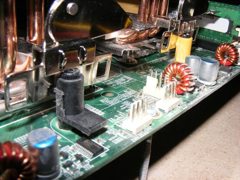
Next, you need to prep your board to mount these heatsinks. You have two options. First, you can cut the heads plus about ¼” off your 2” bolts. The benefit is that you won’t need to mod your motherboard, but the downside is that you may ding up your threads cutting the bolts. The second option is to run the bolts up from the bottom of the board. The benefit here is that you don’t need to modify the bolt. The down side is that with every G34 board I have seen, you can’t run a bolt completely through the mounting bracket – it looks like you can, but you can’t. There are two ways to remedy this. If you happen to have a #6-32 tap, you could run it through the mounting hole and make threads in what currently stops you. The other option is to take a drill with a 5/32: bit and drill a very small amount of material out of the bottom of each mounting point to allow a bolt to thread through from the bottom. I used a through-bolt and the drill method on mine, and everything works fine. For either option, #6-32 x 2” bolts are required – they are actually about ¼” too long, but will work at 2”. Here is my board with the two bolts installed, ready to mount the heatsink (the other three heatsinks are already installed.)

I salvaged two of the original tension springs for mounting because it should keep equal tension on each side even if you don’t get the nuts tightened identically. This also helps prevent over-tightening. You probably could just use a flat and split washer, and would then be able to use a 1 ½” bolt instead of 2”. Either way should be fine, just be careful to not over-tighten the nuts. [EDIT: I don't think I would use the springs for a vertical board mount. The HSFs can tilt over, and might if you jar the case. Since all of my boards are horizontal, it is not a problem for me.] [EDIT #2: After hearing about a couple of successes with not using the tension spring and what sounds like a much easier install, I'm going to officially say you should not use the tension springs and instead use a split washer. I have adjusted the split washer quantities accordingly.] For each side, you need a tension spring, flat washer, and hex nut. For TIM, I just put it on the heatsink and spread it evenly. This seems to work fine – my temps are quite good, and removing the heatsink shows good even coverage. Once your TIM is applied, set the heatsink on the CPU, with the bolts coming up through the center slots in your new brackets. It should slide down pretty easily and not have a whole lot of play side-to-side.

The next part is the most difficult – actually attaching the heatsink to the board. Be very careful with this. You need to get a tension spring, flat washer, and nut on each side. With a 2” bolt, you will need to tilt the heatsink one way or the other to give yourself room to fit the parts over the bolt. You can also slide the heatsink slightly side to side to help create room for the hardware. Get the hardware on one side and snugged down finger tight, then work on the other side. Again, there is very little room to do this, so take your time and be careful. Here are some pics of the hardware installed and finger-tight:


Once the hardware is installed and finger-tight, use your 5/16” open end wrench to tighten the nuts. You will only be able to turn the nuts 1/6th of a turn at a time. Tighten one side a little bit, then the other, switch back and forth until both tension springs are compressed somewhere around half way. The X-brace should end up bowed slightly, which is fine. Once both sides are tightened, you will still be able to twist the heatsink a little. That is also fine. This is what you should end up with:

Once you have all of the heatsinks installed, mount up your fans. Depending on your memory heatsinks, you may need to mount your fans a little higher than normal to clear. This is easy to do with the CM Hyper 212+ fan mounts. The finished product should look like this on an SM H8QGi:


The big question many of you may have is, will this work on the newer SM H8QGL boards with the terrible CPU socket placement? The answer is, yes it will. You can even mount all of the fans the same way. The two sockets are pretty snug, but it does work. Here is my H8QGL board with 212+’s mounted. Temps are very good at 42C max with 6172s @ 2.36GHz.


Tips and Tricks:
- Start with the CPU socket closest to the PCI-e slot(s), and work your way toward the top of the board. While you can get to the middle sockets with all the heatsinks mounted, it is easier to work your way from bottom to top.
- Install the memory after the heatsinks are installed, and before you install the fans. It is a little tight, but you can get to everything.
- Be careful where you rest your hands when threading on hardware and tightening. It is pretty easy to set the heal of your hand somewhere on the board where you shouldn’t.
Here is an alternative to R-Type's CM Hyper 212+ mounting on a G34 board. Due to space constraints, mainly with SuperMicro 4p boards, this method is necessary to allow you to use these HSFs.
Parts List
Knape & Vogt PK255 ZC 24 – 24” zinc shelf standard – 24” is enough for 4 x HSFs, 36” is enough for 7 – these are commonly available at about any hardware or home improvement store
http://www.hardwareworld.com/Pk255zc24-24in-Znc-Shlf-Standard-pTVE2G7.aspx
http://www.amazon.com/gp/product/im..._image_text_0?ie=UTF8&n=1055398&s=home-garden
16 - #6-32 x 3/8 taper head bolts
24 - #6 split washers
24 – #6-32 hex nuts
8 - #6-32 x 2” taper head bolts
Instructions
You’ll notice that this shelf standard has 1/8 x 3/8 slots in a ½” on-center pattern. You actually need a 1” OC pattern, so using every other one works perfectly. Starting at one end, count in 5 slots and cut between the 5th and 6th slot. Ignore the round single and double holes – you may actually end up cutting through them if they fall between a 5th and 6th slot. To cut this stuff, you have several options. I used a metal chop saw I happen to have for mine, but you could use a cut-off wheel on a Dremel tool or even a pair of tin snips. Here is a pic of a couple I just made using tin snips, which would work just fine. I did straighten up the ends a little with some pliers since tin snips will flatten the channel. Note that the one on the left has a single and double set of holes within it. This will not hurt anything.
Next, you need to enlarge the width of the center slot slightly. This can be done a few different ways (Dremel, file, etc.), but it is probably easiest with a pair of pliers to hold the piece and a drill with a 5/32” drill bit. Just be patient with it – the drill bit will thread its way through the slot and try to bind. It will eventually free up and allow you to move the bit back and forth in the slot to enlarge it. Test with one of your #6-32 bolts to make sure it goes through the slot easily.
Now, your brackets are finished. It is time to mount them to the X-brace that came with the HSF. The first thing you need to do with the X-brace is remove the bolts that are attached to it. They are held in with retention clips – with some needle nose pliers and a little patience, you can pull them off to remove the bolts and springs. Once you have them off, get 2 of your #6-32 x 3/8 bolts, 2 split washers, and 2 #6-32 hex nuts. You want to bolt the two brackets you just made to the X-brace as shown in the pictures below. The bolts need to go through the X-brace in the furthest out position. Pay close attention to the orientation of the brackets to the X-brace – again, use the pictures for reference. Just snug the bolts down for now – no need to tighten them too tightly just yet.
Open up the X-brace and thread it through the heatsink, then close it down to the position shown in the following picture. This is a little tricky because everything fits together pretty tightly. You will need to hold the X-brace up to the heatsink base while you rotate the new brackets into position. The alignment key on the heatsink base will line up with one of the slots in the X-brace if everything is together correctly. Once everything is together, thread two more of your #6-32 x 3/8 bolts through the X-brace and your brackets. The good news here is, the slots are tight enough that the bolts will actually thread through them and hold everything together when you flip the heatsink over to install the rest of the hardware.
Flip the heatsink over and add a split washer and hex nut to both bolts you just installed. Tighten all four of the bolts now. The bracket assembly should look like this when you are finished:
Note that the new brackets barely clear the heatpipe tubes, so the whole assembly when bolted together stays pretty much stationary with not a lot of movement. This is correct, and has the side effect of making it easier to actually mount the heatsink to the board. I’ll point out one more thing – you will notice that the slots you enlarged in the new brackets (these are the actual mounting holes now) are under the heatsink fins. You can’t get a screwdriver or allen wrench to them easily like you usually can when mounting heatsinks. This is why I recommend the board attachment method described below. If you have a better idea that works, I would love to hear about it.
[Side note: If you have a rivet gun and 1/8” rivets, that would be an easier and cheaper way to attach the brackets to the X-brace. There will be no significant stress on this assembly, so rivets would have plenty of strength for this application. I do not own a rivet gun, so I could not try it.]
Next, you need to prep your board to mount these heatsinks. You have two options. First, you can cut the heads plus about ¼” off your 2” bolts. The benefit is that you won’t need to mod your motherboard, but the downside is that you may ding up your threads cutting the bolts. The second option is to run the bolts up from the bottom of the board. The benefit here is that you don’t need to modify the bolt. The down side is that with every G34 board I have seen, you can’t run a bolt completely through the mounting bracket – it looks like you can, but you can’t. There are two ways to remedy this. If you happen to have a #6-32 tap, you could run it through the mounting hole and make threads in what currently stops you. The other option is to take a drill with a 5/32: bit and drill a very small amount of material out of the bottom of each mounting point to allow a bolt to thread through from the bottom. I used a through-bolt and the drill method on mine, and everything works fine. For either option, #6-32 x 2” bolts are required – they are actually about ¼” too long, but will work at 2”. Here is my board with the two bolts installed, ready to mount the heatsink (the other three heatsinks are already installed.)
I salvaged two of the original tension springs for mounting because it should keep equal tension on each side even if you don’t get the nuts tightened identically. This also helps prevent over-tightening. You probably could just use a flat and split washer, and would then be able to use a 1 ½” bolt instead of 2”. Either way should be fine, just be careful to not over-tighten the nuts. [EDIT: I don't think I would use the springs for a vertical board mount. The HSFs can tilt over, and might if you jar the case. Since all of my boards are horizontal, it is not a problem for me.] [EDIT #2: After hearing about a couple of successes with not using the tension spring and what sounds like a much easier install, I'm going to officially say you should not use the tension springs and instead use a split washer. I have adjusted the split washer quantities accordingly.] For each side, you need a tension spring, flat washer, and hex nut. For TIM, I just put it on the heatsink and spread it evenly. This seems to work fine – my temps are quite good, and removing the heatsink shows good even coverage. Once your TIM is applied, set the heatsink on the CPU, with the bolts coming up through the center slots in your new brackets. It should slide down pretty easily and not have a whole lot of play side-to-side.
The next part is the most difficult – actually attaching the heatsink to the board. Be very careful with this. You need to get a tension spring, flat washer, and nut on each side. With a 2” bolt, you will need to tilt the heatsink one way or the other to give yourself room to fit the parts over the bolt. You can also slide the heatsink slightly side to side to help create room for the hardware. Get the hardware on one side and snugged down finger tight, then work on the other side. Again, there is very little room to do this, so take your time and be careful. Here are some pics of the hardware installed and finger-tight:
Once the hardware is installed and finger-tight, use your 5/16” open end wrench to tighten the nuts. You will only be able to turn the nuts 1/6th of a turn at a time. Tighten one side a little bit, then the other, switch back and forth until both tension springs are compressed somewhere around half way. The X-brace should end up bowed slightly, which is fine. Once both sides are tightened, you will still be able to twist the heatsink a little. That is also fine. This is what you should end up with:
Once you have all of the heatsinks installed, mount up your fans. Depending on your memory heatsinks, you may need to mount your fans a little higher than normal to clear. This is easy to do with the CM Hyper 212+ fan mounts. The finished product should look like this on an SM H8QGi:
The big question many of you may have is, will this work on the newer SM H8QGL boards with the terrible CPU socket placement? The answer is, yes it will. You can even mount all of the fans the same way. The two sockets are pretty snug, but it does work. Here is my H8QGL board with 212+’s mounted. Temps are very good at 42C max with 6172s @ 2.36GHz.
Tips and Tricks:
- Start with the CPU socket closest to the PCI-e slot(s), and work your way toward the top of the board. While you can get to the middle sockets with all the heatsinks mounted, it is easier to work your way from bottom to top.
- Install the memory after the heatsinks are installed, and before you install the fans. It is a little tight, but you can get to everything.
- Be careful where you rest your hands when threading on hardware and tightening. It is pretty easy to set the heal of your hand somewhere on the board where you shouldn’t.
Last edited:
As an Amazon Associate, HardForum may earn from qualifying purchases.
")