Project Sulaco

tobyak

n00b
Joined
Aug 11, 2011
Messages
57
projectsulaco.jpg


Hello All

So, im new here this will be my first of hopefully many project logs,
in the first few posts ile outline the project and whati hope to end up with

Including my inspiration, how im going to get the job done (were talking a low enough budget to make a victorian family cringe)

And hopefully gather some interest for tips, help and some much needed support

I have a background in design and a lot of plastic scratch building from an addiction to 40k in my youth. As i lack a lot of the serious tools i will be coming up with some interesting ways round common problems

By the end of this i shall be hence forth known as "Dremel Boy" or if the cutting wheel slips "The 9 finger Noob"

So watch this space for what could be either an epic tryumph or epic fail... but hell either way should be interesting

First up some of the sources or inspiration, I suspect most can have a good guess from the project name


sulaco-ir3.jpg

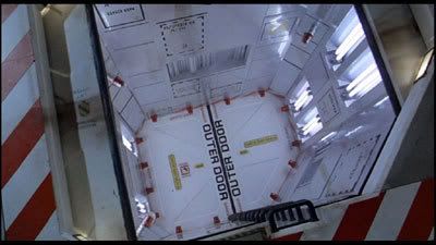
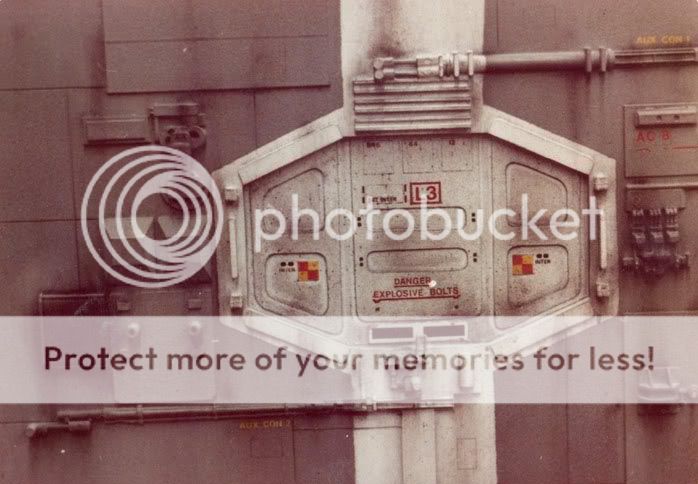
The good Old USS Sulaco, Marine carrier ship from Aliens

dsulaco1cm5.jpg


013-Aliens-2_L72.jpg

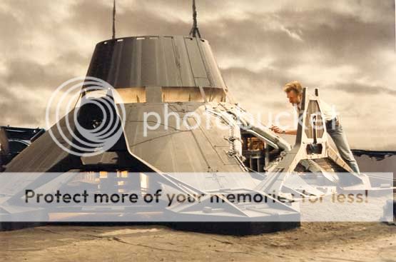
The Atmosphere processors may best reflect the feel, its heavy industry with big lines and chunky details

The case i am going to build on to is the NZXT Tempest EVO
top.jpg


Chunky Styling is allready a feature so it should be a superb platform to build on to

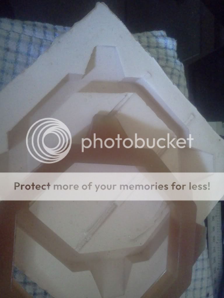
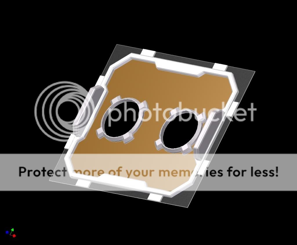
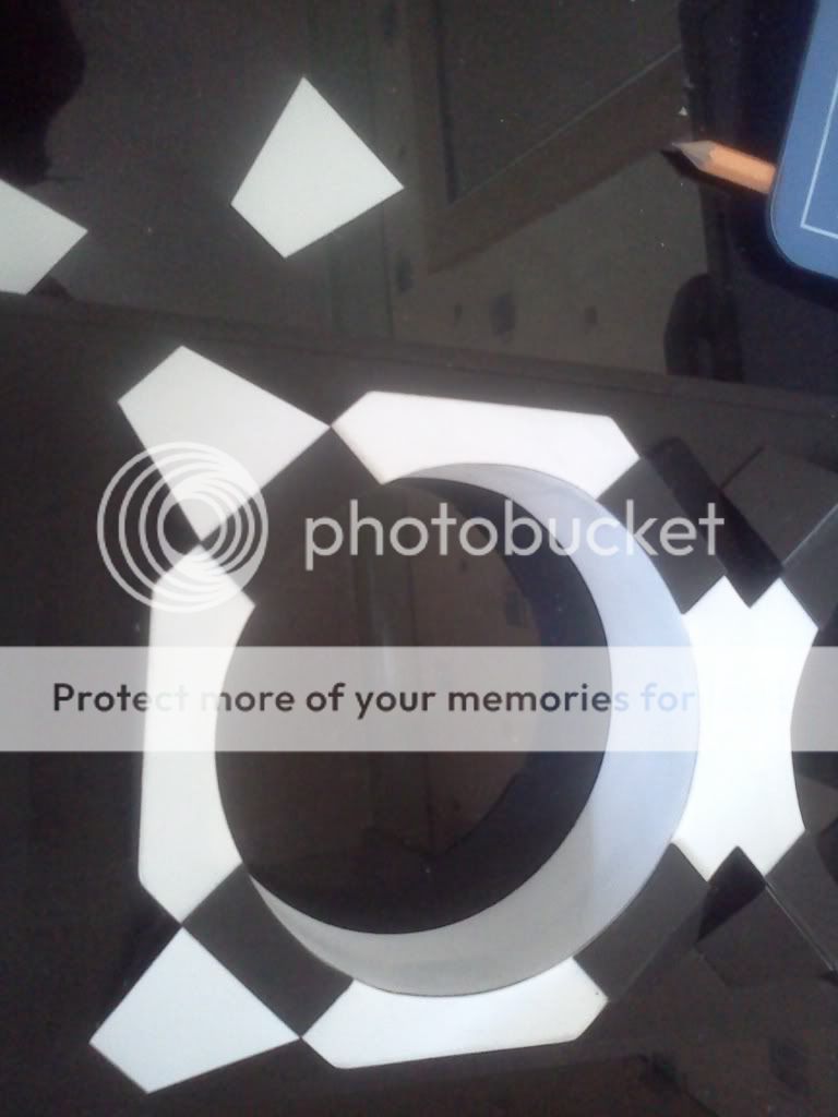
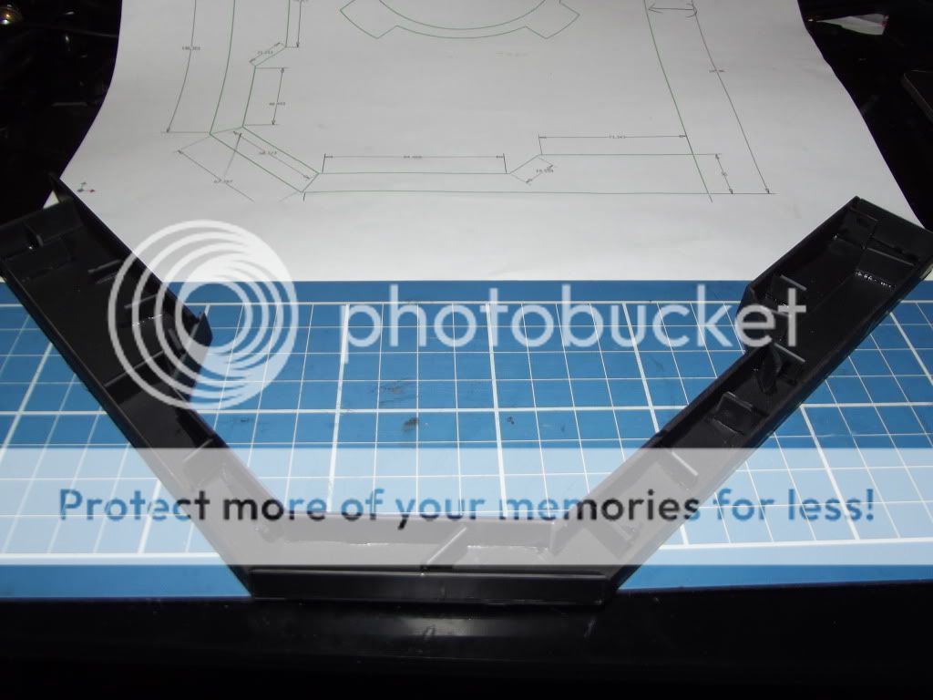
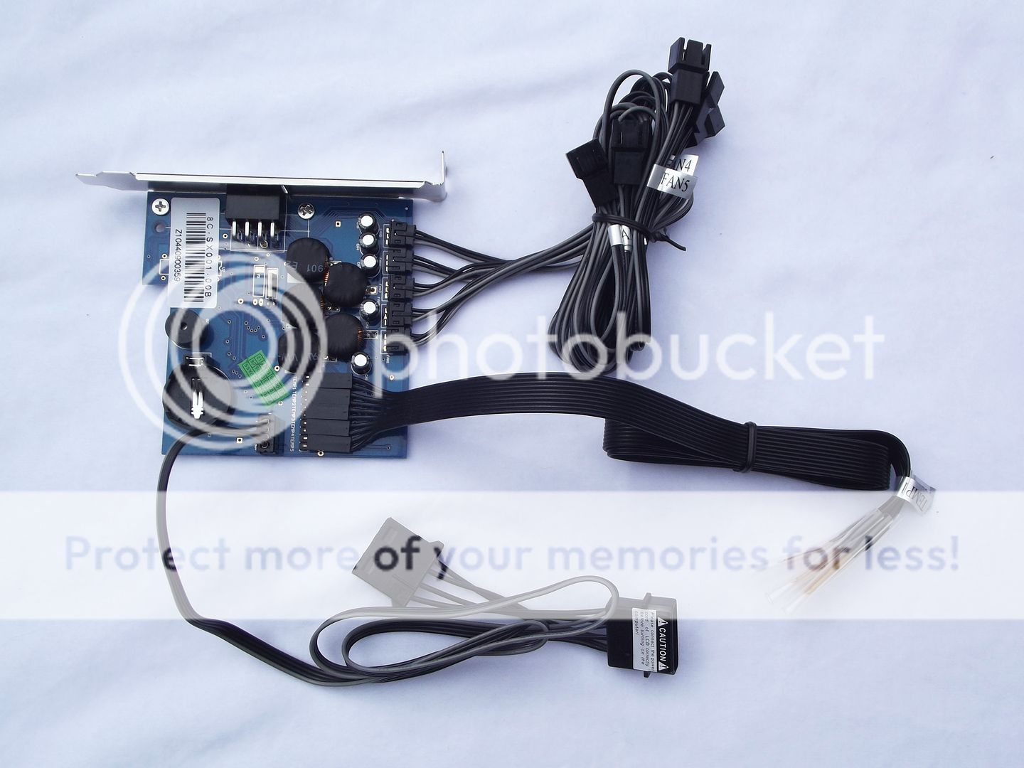
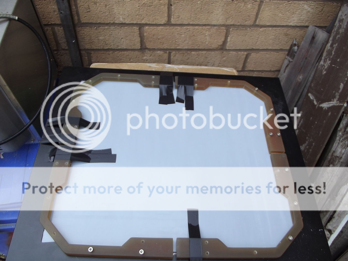
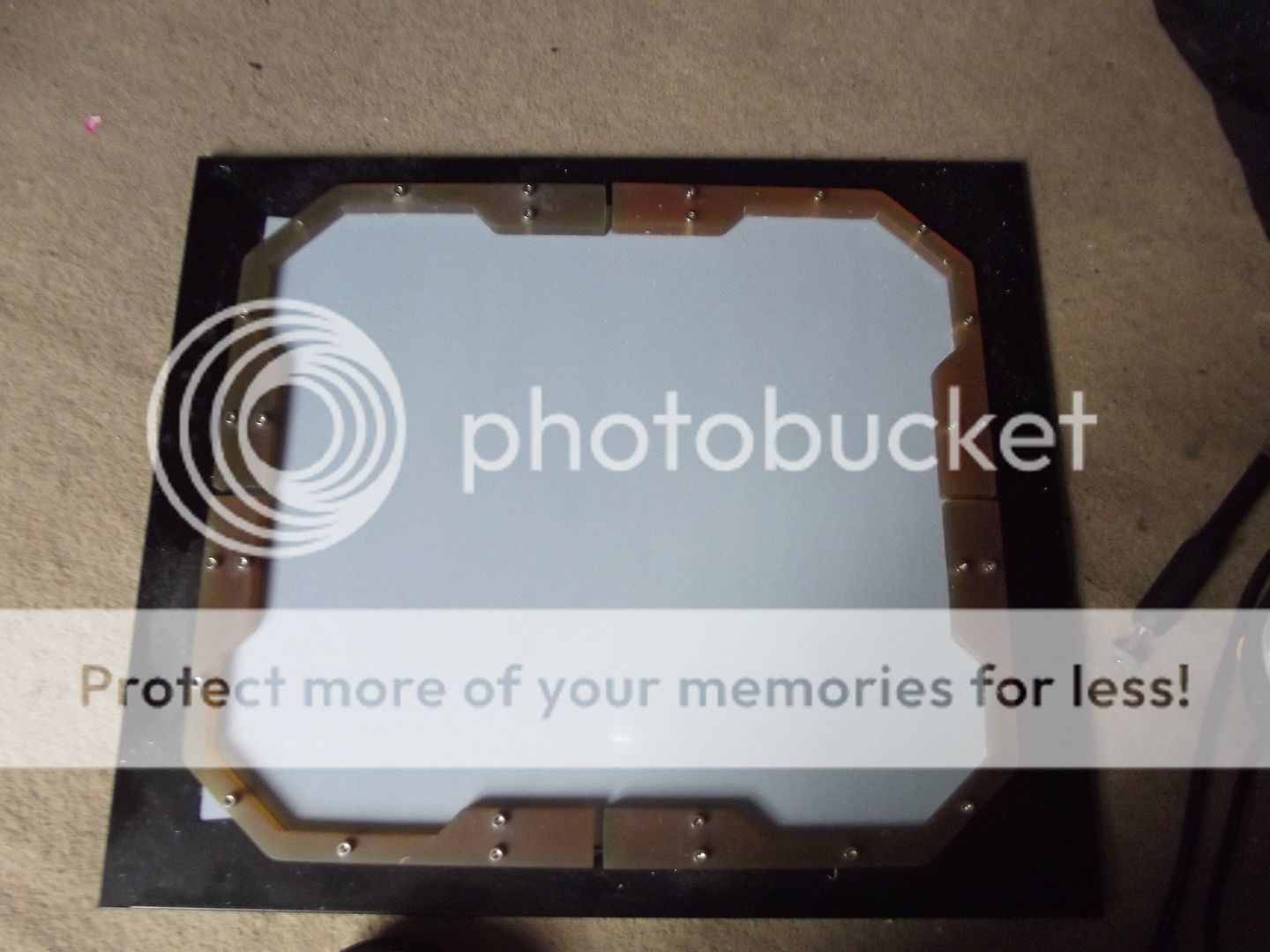
So were going with chunky industrial lines and a plated metal look to it, fan grills currently in design phase (OMG there huge) pics soon


SO why choose an NZXT Tempest evo?

Well lets look at its attributes
evospecs.jpg

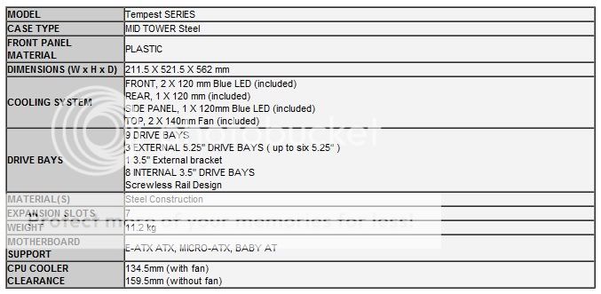
For a midtower this is huge.. and that's with a capital HU!
Steel Chassis, sire its not light but it sure as hell can take punishment and support some seriously heavy gear

And of course every ones concern.... cooling... although it has none of the trappings of 20mm fans it sports plenty in the 120mm to 140mm range. for me (A die hard air cooler)
it is perfect, but also sports 5 water-cooling grommets
Did i mention the case was big???
And on a final note... the case is big lol

Side on
nzxt-tempest-evo_2.jpg

6.jpg

Large tinted window and 120m fan with filter. A slight departure from most windows as it is mounted outside the case sitting proud of the side panel, it really helps to keel the case symetrical whilst also gaining a slight amount of extra clearance for the larger aircoolers out there

Inside
nzxt-tempest-evo_4.jpg

Well we are back to "ITS HUGE" no more bleeding fingers from case edges for me, i can in stall my rig in this and use it as a spare room for guests, its clutter free and the HDD racks are tool less and can be removed completly for GFX card space or for controlers to be hidden away behind the front support


Top
IMG_4874.jpg

Recessed ports prevent them getting kicked or knocked... we all know the pain of hearing a crunch leaning over our pc and viewing the horror of a USB plus pointing 45deg out of the port, well break your ports no longer... and the area infrobt makes a handy dandy place to keep memory cards (well for me anyway)


It has great strong lines and a sharp clean shape, its huge panels leave plenty of space to mod in to/ on to/ over or through, its such a huge case with so many possabilities offered my its strong frame and sheer size that it was a huge headache picking a theme to use

I have been an NZXT fan for years, right back to the LEXA, and we are talking pre blackline edition

So without further boring you all to death (condolences to those who died of bordom reading)

Project Sulaco............​
 
Bit if a post backlog dump today folks, get your reading glasses


To compliment my fans for this build (ENRMAX Apolish Vegas blue) I wil be making my own custom grill/intakes
2_r.jpg


First mock up of the front grills, all hand made form plasticard, sorry no work pics for these at this stage in the build i had not picked up a decent camera

IMG20110515_001-1-1.jpg


Ahh plasticard my new BFF

90440_Plasticard_450.jpg


All constructed in .5mm plasticard, slightly smaller then you would expect for a 120mm intake


Finishes intake fresh out of the mould, at this stage they are very brittle, and need to cure for several days, maybe even a month to be on the safe side
IMG20110730_001.jpg


Twin mk1 intakes and cutouts for Silverstone media panel, and blue ray drive, layed out to test fitting and space on the panel
IMG20110515_003.jpg

And yes i know the intake flanges are not perfectly symetrical.... i have a cunning plan for that later

NOTE, allways use a canister filter mask when working with polyester resin... i did not, took 3 days before i stopped seeing double


Had some spare time today between work and fending the kids of with a dremel os have doen the prelimiary design of the side panel for Project Sulaco. Very Industrial with big intakes, think of it as a cross between an indulstrial cooling system and an escape/airlock

Prelim sketch (no laughing it was quick lol)
sketch.jpg


First stage, wire frames and checking the size works for styling
wirefront.jpg

wireoblique.jpg

Materials :


Renders of the window (not true colour)

frintview.jpg

obliqueview.jpg

Still a lot more design to do before i can start some serious fabrication​
 
Here is a few more shots of some elements that are driving the design

Sulaco inner airlock[/B]
cap040.jpg


Exterior airolock of the Nostromo
lock.jpg

Why have a note on the OUTSIDE of the airlock warning against explosive bolts... if you are outside to be reading that then the bolts are the least of your worries

I am hoping to incorporate some of these details in to the finished design, perhaps not to clean and clinical as in the Sulaco's inner airlock but cretainly with the same sturdy build


Awaiting supplies for casting and some materials so on with the bezel....

First things first, test fitting
IMG20110525_002.jpg

However soon a problem arises, IE the flanges on the surrounds are not symetrical, a minor disaster but not the end of the world. i have a cunning plan.....

First up, covering up that nasty gap between the 2 intakes with a fresh sheet of plasticard, set i place with 2 part epoxy
IMG20110616_007.jpg


Then i needed to begin forming it to the original lines of the intakes, without some better tools then i have its time to make use of the sturdy kraft knife and some precision files, making lots and lots of incise cuts to edge my war closer to the main form, the feathering this creates also makees the final cut off much easier
IMG20110616_006.jpg

IMG20110616_004.jpg


3 Hours later
IMG20110616_001.jpg

IMG20110616_003.jpg


Next up, giving it that deep set duct that i so wanted to look lik an air con or ventilation unit

For this I had to use several strips and glue then end to end to get the length strip i needed, left to dry for 48hours, a huge amount of time to dry poly ut as the glued join measured 20mm X 0.5mm it needed to be solid
IMG20110625_002.jpg

IMG20110616_002.jpg

IMG20110618_002.jpg


Once the epoxy on the reverse has set i can go ahead and poly the join between the edge of the duct and the top sheet, i have allowed some extra material to remove later, I am sure all of us would rather need to remove more rather then find we had not removed enough
IMG20110618_001.jpg

IMG20110618_003.jpg


Exterior airolock of the Nostromo
lock.jpg
[/CENTER]

Why have a note on the OUTSIDE of the airlock warning against explosive bolts... if you are outside to be reading that then the bolts are the least of your worries

I am hoping to incorporate some of these details in to the finished design, perhaps not to clean and clinical as in the Sulaco's inner airlock but cretainly with the same sturdy build

Why not put the explosive bolt warning on the back panel about the screws holding the side panels on? :D
 
Huge bonus points are in order for doing your work atop a Jack Daniels blanket/towel/placemat/whatever.
 
Can't wait to see the finished product. Subscribed!

I really hope you have a year spare, apart from my trusty rotary tool and a drill it will be hand tools all the way... not looking forward to cutting 5mm alu
 
WOW hot day, wish i was outside but needs must, i simply haft to get these flanges fixed. The flanges on the corners were not exactly symetrical so i had the idea to raise the whole section and build a fake box on top of them to the exact shape i wanted, once drawn up and measured the gluing was easy, BUT they are only attached by there ends until i can get the side pieces put together

IMG20110625_004.jpg


Attached the flange sides, the beauty of this is you dont need to havean exact shape, you use the join to guide your cut
IMG20110625_005.jpg


Finished with all flange sides added ready for first coat, as i am using plasticard for the main construction i am using a VERY thick application of satin PlastiKote clear over a matt black, not for the final finish but to provide me with a hard shell to work on top of
IMG20110627_001.jpg


Whilst i wait for my joints to dry ive taken some spare time to make the replacement NZXT logo and AMD logo

AMD logo done, a lot less tricky then i expected
IMG20110627_004.jpg


NZXT logo almost sorted, most of the letters turned out fine although i am on the 16th letter X
IMG20110628_001.jpg


All letters finished with a little plinth to place on
IMG20110628_004.jpg


DONE yay!!!!
IMG20110628_007.jpg

And yes those letters are 13mm high


Time to start working on the mould for the window surround, i willl be using a master blank to provide the shape for the finished surround, and will be casting the mould from silicone RTV
moldes01.jpg
or a lubricated alu box (setting resin can get up to 80C and will melt plastic)

Final produce till be cast in Polyester resin
polyester-resin.jpg


Render of the Bezel i wil be making, caution will be the key here as the polyester resin can be brittle in the cross section i will be working in
bezel.jpg
 
BIG update today

With a huge influx of materials and some glorious free time ive managed to start on the blank to be made in to a mould for my resin window bezel, main blank fabrication is from 3mm plasticard, and wil be all hand cut and filed to prep for moulding, all joints will be made with polycement, it is quick cheap and effective for this material

Once marked out i can start to score the lines to create a guide path for the scalpel
IMG20110808_004.jpg


All lines nice and deeply scored, the depth of each cut is now approx 2.5mm deep, the component can be snapped free after this point
IMG20110808_003.jpg


And behold the first piece of the mould blank, the most critical piece as this wil govern the placement of the rest of the structure and any reinforcing needed
IMG20110808_005.jpg


Cutting out the "rails" that i will split to make the sides and reinforcing butresses
IMG20110808_009.jpg


First few sides and supports added, due to the pressure of 24hours immersed in a very dense liquid such as Silicone this needs to be very strong to prevent warping f the flat surfaces
IMG20110808_011.jpg


Construction continues
IMG20110808_013.jpg


And now finialy, my new camera, say god bye to dodgy phone camera pics

MY new Fuji all singing all dancing camera.. if this was any smarter it wold be a professor as Cambridge
IMG20110810_001.jpg


New Arrivals


Hmmm i wonder what they could be, i shall use my jedi powers to detect the cargo... I predict the one on the right are fuel rods and the one on the left is a very angry Chinhilla
DSCF1033.jpg


Damn i was wrong....

DSCF1063.jpg

And....

DSCF1034.jpg

Yes the sweets did come with it, weird​


Lets take a closer look...

Silicone RTV (Liquid silicone component)
DSCF1035.jpg


Catalyst component
DSCF1038.jpg

For this brand the mix is 1/10 catalyst to silicone, most have a ratio of 1/5 for the "salmon" catalysts. This is a clear catalyst mix better suited to exposure to Polyester resin

Class is shore A (20), i very resiliant silicone mix with high thermal resistance and strength, not as elastic as some classes its tearing ratio is 400% elongation


And now the cathodes....

Whats in the box

4 UV CCFLs
DSCF1073-1.jpg


2 twin inverters
DSCF1068.jpg


On/off rocker switches and cable bundle (ugly and will be replaced and sleeved)
DSCF1070-1.jpg


Assorted sticky bits
DSCF1071.jpg


UUUUU purdy (chair not included)
DSCF1074.jpg


Finishing the mould, had a good bit of time to work today so ive finished the blank and set up the mould walls to retain the Silicone RTV

My two best friends polycement and a scalpel
DSCF1077-1.jpg


Blank finished with all the reinforcing in place, and poly is set
DSCF1082-1.jpg


Lets break out the sander.... MORE POWER!!!!
DSCF1085.jpg

After some brief but interesting sanding where my pet Staffordshire Bull terier tried to eat the mouse sander i finialy got the edges nice and crisp and the bottom level all ready to glue to the sheet that will form the base of my mould

Crisp, clean.... and erm.... dusty
DSCF1088.jpg

DSCF1091.jpg


Brushed off the dust and debris and glued the blank to the mould floor
DSCF1094.jpg


Lots of spare plasticard cut in to strips to form the mould wall
DSCF1097.jpg


Mould all done all ready for the RTV to go in
DSCF1102.jpg
 
Time to mould


Everything you need to make the mould
DSCF1104.jpg

Pictured above, all the things you need to finish one single part mould

  • Spatula
  • Silicone RTV
  • Catalyst
  • Blank
  • Mould box
  • Mixing vessel.... (my wife's fave cake tin)
  • Rice

As this is not a regular shape mould it is hard to work out the volume do you dont over or under mix a quantity of silicone

Fill your mould with rice until you have the blank covered to a depth that you feel you want for mould
DSCF1106.jpg


Pour off the spare rice and empty the mould in to your mixing vessel, then mark the level the rice comes to as your "max fill" level
DSCF1107.jpg


Although you may think that another approach would be to weight the rice for maximum accuracy but DONT, Silicone RTV is far more dense that rice and you will not get the same volume

Place your mixing vessel on some weighing scales and make sure you zero the reading... pour in the Silicone to the fill line.... make a note of the weight
DSCF1110.jpg

DSCF1109.jpg


As this is a 1-10 mix catalyst you need 1/10 (BY WEIGHT) so from the note you made on the scales work out a tenth and pour in the catalyst until you reach that weight
DSCF1111.jpg


NOTE - The catalyst that comes with this brand of RTV is clear, i have tinted it with silicone dye for photographic use and to better illustrate a good mixture
DSCF1112.jpg

DSCF1113.jpg

DSCF1114.jpg


And now we are ready to pour, do it slowly and try to avoid moving the pour stream around to much in the early stage as you will trap air bubbles
DSCF1116.jpg

DSCF1118.jpg


Pouring done, let it settle and check after an hour to see if the surface if free of bubbles, if it is not pop them, remember this will become the bottom of the finished mould and must be perfectly flat
DSCF1119.jpg

DSCF1120.jpg


Time to demould

One of the good ways to see if your silicone is ready to remove from the mould is to look at the surface it will lok tight and will have lost most of the shine it had as a liquid
DSCF1123.jpg

Another popular but less scientific method would be "prod it a bit"

As with most materials set with a catalyst the thicker areas set first so to be 100% sure that it has set pull away one side of the mould to release the seal if its to soft push the side back and wait another 3 hours
DSCF1124.jpg


Start taking the sides off our mold, NEVER try to take it out like a jelly mould, the suction from the material will more then likely destroy your blank and mould block before it becomes free
DSCF1125.jpg


Starting at one edge peel the mould off the blank, this way you break the suction as you go
DSCF1127.jpg


TADAAAAAA!!!!!!!!!!!!!!
DSCF1128.jpg


Little bit of flashing around the mould edges, very easy to trim off
DSCF1132.jpg
 
Bomber update!

I have an APBTISH (American Pit Bull Terrier... ish), think your staffy but dumber.. she started leaking puss & blood mixed on the floor yesterday morning O_O.


Hello $600 trip to the vet!


This Mod is looking incredible. You are making me itch to get molding!

Edit: Original term for the nasty leaky fluid changed - the dog is fixed, and was not leaking from that region @_@
 
@formula409 cheers dude

@jarhead 2 part moulding coming later, casting coming in next update

@Riboild thanks dude, hopefully now ive got the backlog out of the way i can slow and make sure i can keep my quality up

@ mannyman got to have some humor or its a giant how too manual, for my next trick juggeling SSDs.. note to self beg wife for SSDs, when she asks why do not say juggeling

@ Wiregeek the itch may be an allergy you may want to get that looked at lol

@dogbyte_13 Khorn and Tau FTW
 
Time to do the casting

DSCF1137.jpg

What do we have
  • Resin
  • Catalyst
  • Mould
  • Mixing bowl
  • Mixing device


Raw polyester resin
DSCF1138.jpg


Catalyst added
DSCF1139.jpg


Mixed, note the darker tone now, its an effect of the mix forming chemical bonds changing the structure, some of you will know this as "curing"
DSCF1141.jpg

this is a 100/1 mix ratio, resin to catalyst, but i am rounding up to the nearest gram, in this case 170g resin needs 2g catalyst, i weighed the amounts out before i started to save myself some time

Sorry no pics of the pouring, the fumes liberated by the pour can mess up fine lenzes

Pouring done
DSCF1142.jpg


As this is a one part mould you are going to get sunken and risen areas due to surface tension, so you may want to spread the top surface outside the confined ot the moulds sides to break that for a true smooth finish, this only applies to one part moulds where you are filling fight up to the top surface
DSCF1143.jpg


ITS READYYYYYYY!!!!!
DSCF1144.jpg

When cured you will notice its changed to a rather green tone and has some lateral shrinkage

DSCF1145.jpg
You will also be able to make out some hairlike marks in the surface, this is part of the curing process, where 2 curing areas meet they form this boundry line just like a continent

A few of the finished items, on a block of alu to help dissipate the heat, as the resin whilst curing can get up to 80c
DSCF1146.jpg

All 4 parts cast, time to get the mouse sander out

Here we see the mouse sander in its natural habitat, about to pounce on this basking bezel piece
DSCF1156.jpg


10 mins and a lot of swearing later (sanded my finger)
DSCF1158.jpg

DSCF1159.jpg


30mins more and even more swearing (to annoy the neighbours)
DSCF1160.jpg

DSCF1157.jpg


Ready to do the fine sanding ready to box up doe painting later
DSCF1163.jpg

DSCF1164.jpg
 
long way to go, got to start measuring up the alu sheet and waiting for some kickass grills from MNPctech
 
Great work log. It's giving me ideas for a new project. Keep up the great work!

Thankyou, more to come.... its pc strip down day today, poor things getting taken apart so i can measure up the additions, i only hope an alu clad modified Tempest Evo looks as awsome in reality as in my head
 
Its door fabrication time, that means HERE COMES THE DREMEL yay!!!!

First up, lets get this side taken apart
DSCF1186.jpg

DSCF1188.jpg


Tabs off, lets pop the window out
DSCF1189.jpg


I will be using 1.5inch cutting discs from MNPCtech
DSCF1194.jpg


Measuring up the new window bezel and making sure my cut lines are marked well inside the cut.... CUTTING YAY
DSCF1192.jpg

DSCF1196.jpg

DSCF1197.jpg


Deburring
DSCF1201.jpg


Well that took ages lol, but the results are exactly what i need
DSCF1198.jpg

DSCF1200.jpg


Next up, filling the acrylic for the window and starting the cut for the top mounting panel

Unfortunately i couldnt get any shots of cutting the acrylic out as the dust was getting in my camera, co lets ump to filing and sanding the cut edge

I will be using a rough sanding pad for this as i have a lot of material to remove
DSCF1210.jpg


Whoops
DSCF1211.jpg


Ahh there fixed, ther was never a huge chunk taken out of the edge... was there *swings hypnotists watch*
DSCF1213.jpg

In the next post... i start work on the top panel
 
SUPPLY DROP

A few weeks ago i was delighted to hear that NZXT had been kind enough to sponsor my project, for me this is fantastic, although sponsorship is a day to day affair for the more established in the modding community but for the new guy sponsorship is a big risk as they cannot be 100% sure there not being conned or that the project will not fizzle out to nothing. So once again its a HUGE thank you to NZXT


SUPPLIES
DSCF1313.jpg


After mugging my deliveryman and fighting my way in to the packing box (cudos on the secure packing)

Lets see now we have.......

The HALE90 (850watt)
DSCF1314.jpg

DSCF1315.jpg


Sentry LXE
DSCF1316.jpg


Blue LED lighting kits


Unboxing the PSU, what's in the box... well ok a PSU... i ment what else
DSCF1334.jpg

DSCF1355.jpg

Nice to see a total lack of the typical polystyrene in favour for the non crumbely packing.
Everything in perfect condition


The PSU its self, NZXT have gone for white on the HALE90 series, with the recessed grill and 140mm fan the looks are pretty striking, and of course it IS modular
DSCF1341.jpg

DSCF1342.jpg

DSCF1341.jpg

DSCF1345.jpg


Plenty of modular cables provided, all have good quality connectors, and with the all black sheathing have a nice uniform look. and all kept safe in a little carry case
DSCF1336.jpg

DSCF1338.jpg

DSCF1340.jpg


The main loom has plenty of connectors all sleeved in black braid
DSCF1352.jpg

DSCF1354.jpg


On to the Sentry LXE fan control

Again we have the same foam packing to keep it all safe, no part of the LXEs main unit was touching the box it was suspended in the foam for max protection, so many times have i seen components resting on cardboard after removing the cover package
DSCF1322.jpg

DSCF1324.jpg


Main unit is very rugged 5mm alu face plate
DSCF1323.jpg

sadly i could not get a shot of the screen (camera flare central)


Main PCI, Connectors a plenty here with power, 5 3pin PWM fan connectors and 5 temp probe connectors
DSCF1333.jpg

DSCF1330.jpg


They have even included EXTRA temp probes just incase
DSCF1326.jpg


Also included, screws for pci mount, 8 pin pci plate to control lead, pads to affix the probes and a back up battery


Last up the Blue LED strings, nice little blister pack, in the case of components like these i often see way to much in the way of packaging

DSCF1317.jpg


In the box we have pci plate, power lead and the string its self, the one pictured is the BLUE 100CM edition, 200CM is available
DSCF1318.jpg


On the rear plate we have a slider for 3 brightness selections and ofcourse the On/Off switch
DSCF1320.jpg

Once again a massive THANKYOU to NZXT for the sponsorship

nzxt1.jpg
 
BUSY BUSY BUSY, finialy has a chance to get a good run up putting the side pane together and making sure it all fits before final sending and painting

Electrical tape, the modders friend
DSCF1434-1.jpg

This was a nightmare to get all the components in place to drill through what was technicialy a sandwich of cast polyester, steel and acrylic


More drilling.. jeez......
DSCF1432-1.jpg


Making sure the holes line up for bolting
DSCF1452-1.jpg

This could have been a lot easier and faster but with limited resources one hast to think out of the box


Test fitting the bezel
DSCF1444-1.jpg

The gaps are intentional, i will be covering them with brushes alu to add a little accent


Tapping the holes for the fan/grill assembly
DSCF1456-1.jpg


MNPCtech 120mm overkill grills, Bill Owen over at MNPCtech is making 2 140mm versions of these for me for the top
DSCF1454-1.jpg


MORE DRILLING
DSCF1458-1.jpg


MORE, MORE DRILLING.......
DSCF1457-1.jpg


UUUU thats rough
DSCF1459-1.jpg


Most of the forming done, dremel+lap sanding wheel+awesome
DSCF1461-1.jpg


Main door fab finished, plenty of adjusting to come but thats the BIG fab done
DSCF1463-1.jpg
The fans are perfectly central trust me..... CURSE YOU CAMERA ANGLE
NOTE the 2 triangles outside the bezel are intentional, not sure if there going to remain tiny windows or to cut them through in to blow off vents

And no way in hell am i removing the protective film untill im done

So much still to do, but its gunna be great fun
 
Finaly got time for an update, here goes....

Time I started work modifying the NZXT Sentry LXE to modify it for the front of my case top


Cutting is going to take a while, love or hate NZXT most will say there products are sturdy and the LXE is no different, the front bezel is 5mm anodized brushed alu
DSCF1501.jpg


let the cutting begin, for this i will be using the trusty Dremel with MNPCtech.com reinforced cutting discs but even with good discs this will take a while... i will spare you a million shots of cutting
DSCF1502.jpg


2 hours.... YES 2 HOURS later......
DSCF1506.jpg


ok now I have got the bottom off time to make it fit the shape of the case top...... time for this to go on a diet
DSCF1505.jpg

DSCF1509.jpg

DSCF1546-2.jpg


ok now its the correct size
DSCF1503.jpg

DSCF1507.jpg


On to the next problem, this is black anodized and brushed so i have 2 problems... i need bare metal..... AND the brushing is in the wrong orientation

SANDING TIME


Flat sanding using 400grit wet and dry paper, very similar principal to lapping a CPU, but with the larger surface area this will take longer

After 30mins
DSCF1547-2.jpg


After an hour
DSCF1548-2.jpg


After 3 hours and 30 seconds under a mouse sander to rough the surface
DSCF1551-2.jpg


Next up... rebrushing to match the direction of the metal i am using on the case, 800grit wet and dry until silky in apperance (you must sand only in one direction or your just sanding not brushing) after a uniform finish is attained its on to 180gritsand paper untill you end p with...

DSCF1554-2.jpg

DSCF1553-2.jpg

There fixed.... coming up in next post New supply drop
 
Its looking great!

Also at least someone heres back from NZXT they don't answer anything for me.

It must be nice to get free stuff lol.
 
What's on the menu today???...... Filling... mmmmmm my favourite... *Runs ff to cry in the corner*

I hate filling but these things must me done, the first plan for the side had 2 vents on the side of the window using the old window shape as a guide, but on reflection it just looks like I missed a bit so time to bring out the filler

Spot the missing bits??
DSCF1465.jpg


Ok here we go, first up, making plates to fill the gad befor I fill. I have cut off a lot of metal to make the window shape and i need metal of exactly the same thickness to bridge the gap in the panels.......
Light-Bulb.jpg


TADAAAAAAAA use offcuts for spare material
DSCF1556.jpg


OH look a perfect fit.... LLLLIKE A GLOVAAAA!!!!
DSCF1562.jpg

DSCF1564.jpg


Time for the filler, i wont be giving a tutorial on this as most brands differ by huge amounts on the part to part ratios, this one is a 1-50 mix with a working time of 5mins, sandable in 20mins and complete cure in 2 hours
DSCF1560.jpg

DSCF1568.jpg

DSCF1570.jpg

FYI... love the smell of the stuff...... from the yelling i am going to assume my wife does not

Worked with it a little to long but made sure i applied thick enough to get away with it....
DSCF1561.jpg


Now on to the sanding....... there did you like that.. me too
DSCF1572.jpg

After a full cure it is ready to prime but first.....

NURSE???????? BRING IN THE PATIENT!!!!!!!

It is time to operate on the NZXT HALE 90 PSU

I need to get it apart to mask off for priming
DSCF1574.jpg

DSCF1578.jpg

A naked PSU.... shield the children's eyes

Primed. And i found out a matter of note.... spraying in a room with zero ventilation that is only 40cubic feet is not good for you......... but it sure is fun
DSCF1580.jpg
 
Back
Top