Navigation
Install the app
How to install the app on iOS
Follow along with the video below to see how to install our site as a web app on your home screen.
Note: This feature may not be available in some browsers.
More options
You are using an out of date browser. It may not display this or other websites correctly.
You should upgrade or use an alternative browser.
You should upgrade or use an alternative browser.
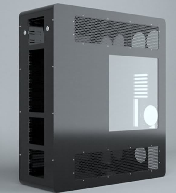
Project: Aluminum Water Cooling Case
- Thread starter Spotswood
- Start date
D
Deleted member 12930
Guest
subscribed!
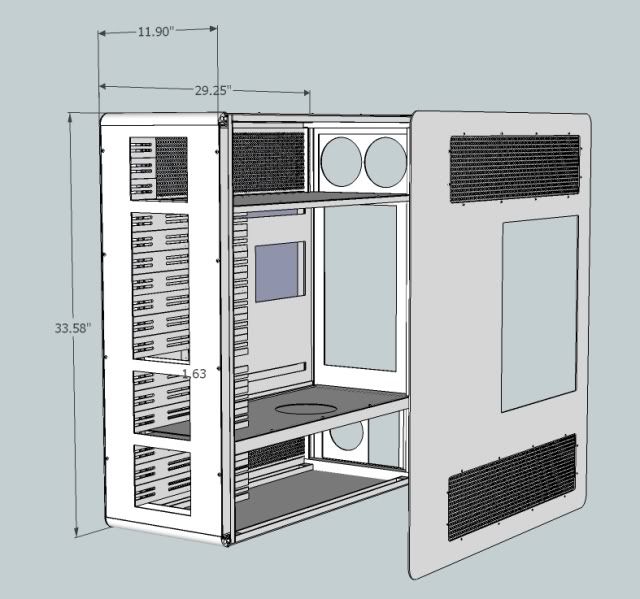
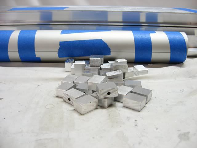
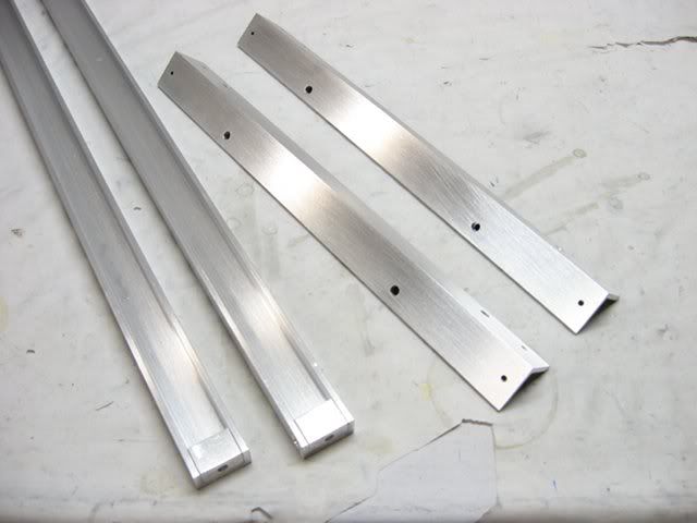
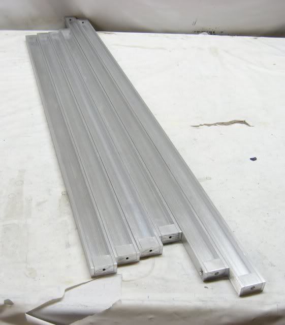
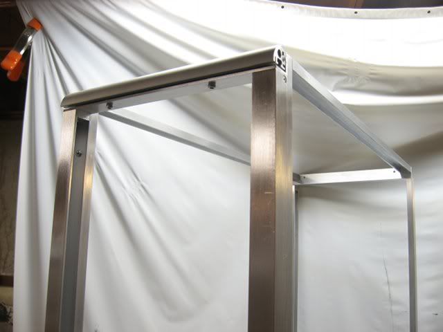
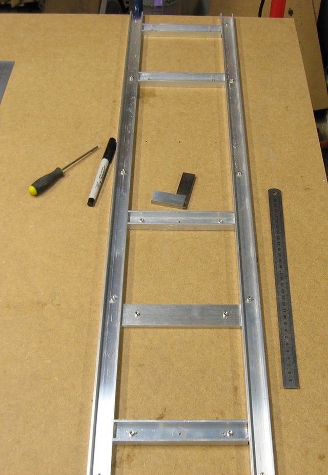
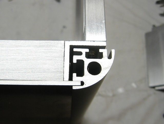
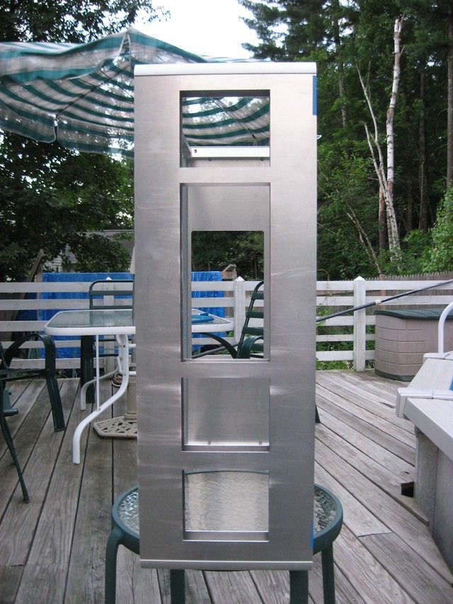
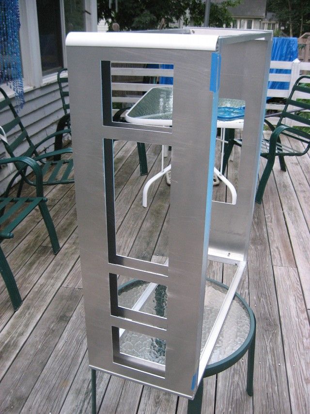
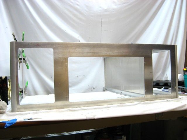
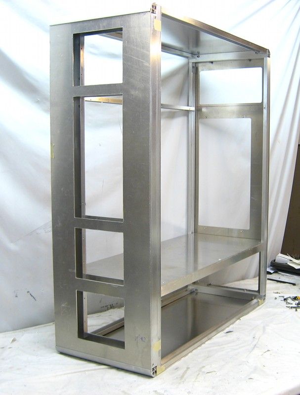
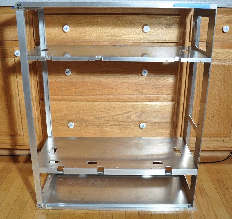
The basic frame of the case is done, which consists of .5x1-inch u-channel with its ends plugged with blocks (pictured in the first post), press-fitted and pinned with a #4 screw along with some 1-inch angle:
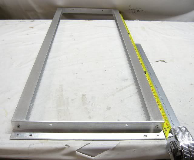
The assembled case frame is too tall to fit in the camera frame. hehe
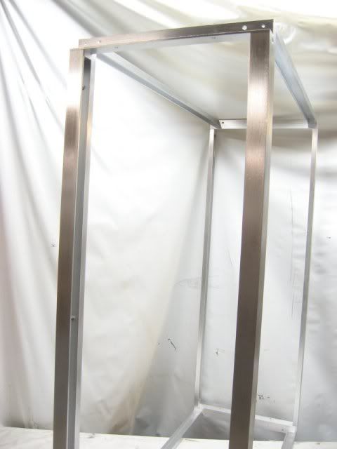
The frame looks kind'a "meh" until I bolt on the gorgeous anodized quarter rounds.
The assembled case frame is too tall to fit in the camera frame. hehe
The frame looks kind'a "meh" until I bolt on the gorgeous anodized quarter rounds.
Avalanche
Pendleton - Learn It, Live It, Know It
- Joined
- Feb 24, 2008
- Messages
- 4,548
Subbed!
vsboxerboy
2[H]4U
- Joined
- Oct 17, 2005
- Messages
- 3,661
Looks great - very Lian-Li with those industrial lines. I like it, especially cause it's not some chunky beast.
Wahoomcdaniel
Weaksauce
- Joined
- May 2, 2005
- Messages
- 117
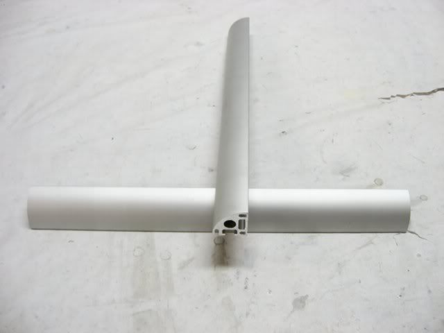
Good work locating and incorporating the aluminum quarter round.
It will make a big difference in the quality of the final product.
It will make a big difference in the quality of the final product.
Good work locating and incorporating the aluminum quarter round.
It will make a big difference in the quality of the final product.
Thanks.
Getting the quarter rounds attached to the frame is a big pain in the ***, but is another differentiator for me, amongst all of the other horrid looking cases out there.

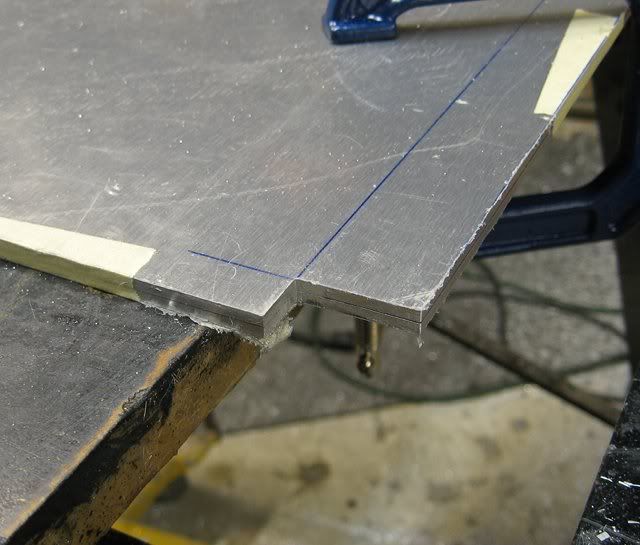
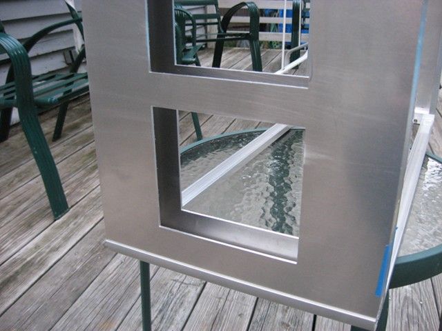
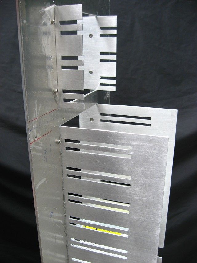
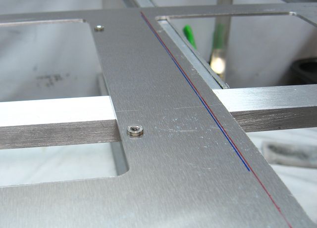
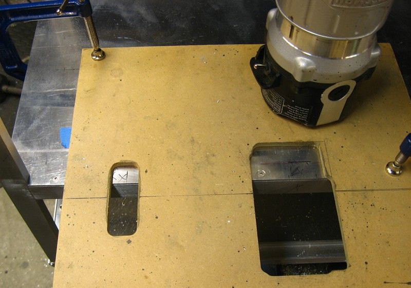
The two shelves were cut from a .10-inch thick 5052 via my trusty router, a straight edge and a downcut spiral bit.
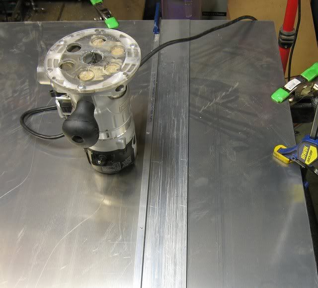
At the back corners of the shelves, two .5x1-inch cutouts were routed out via a temporary router jig.
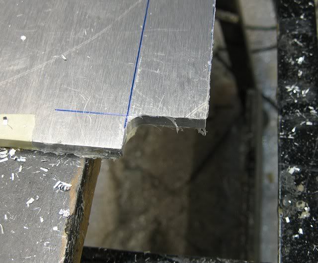
The rounded inside corner left by the .5-inch flush router bit were filed square.
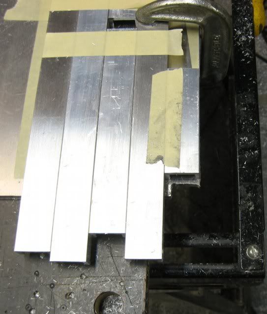
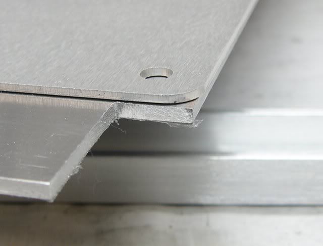
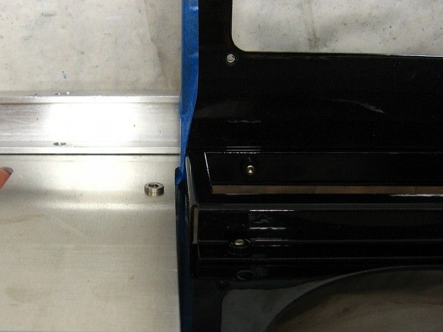
FWIW, here's the difference in the thickness of the aluminum sheeting I use compared to everyone else.
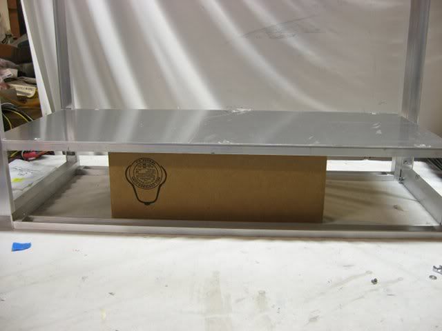
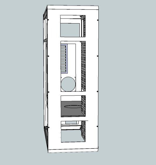
Finally, a mockup of the shelf inside the frame of the case:
At the back corners of the shelves, two .5x1-inch cutouts were routed out via a temporary router jig.
The rounded inside corner left by the .5-inch flush router bit were filed square.
FWIW, here's the difference in the thickness of the aluminum sheeting I use compared to everyone else.
Finally, a mockup of the shelf inside the frame of the case:
How thick is the aluminum? My case has some fairly thick aluminum on it. Looks great so far, Im tuned in.
.10-inch thick.
Thanks..10-inch thick.
Like mine! You can tell the quality, Your case is going to be amazing when its done.
TheGrapist
n00b
- Joined
- Sep 19, 2010
- Messages
- 17
awesome so far,keep up the good work
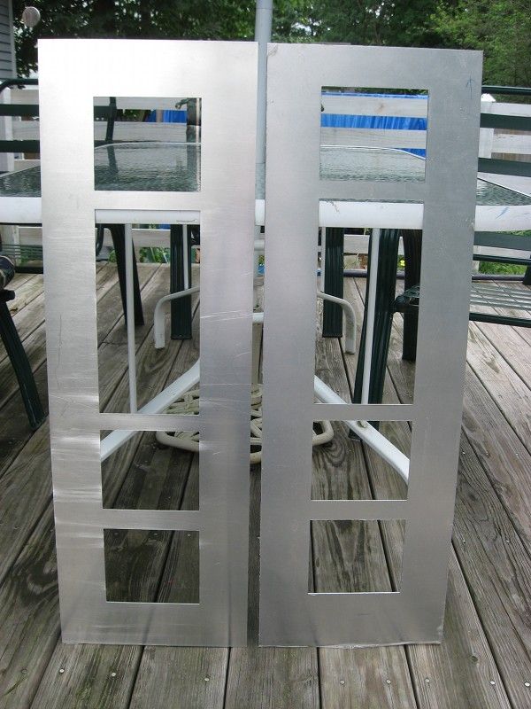
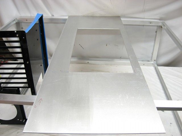
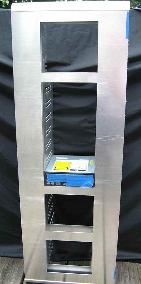
Next up is to cut the front sheet.
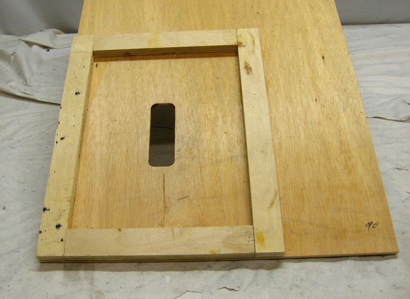
In order to cut-out all of the openings for the 5.25-inch drives accurately, a custom router template is required. I used .5x1-inch u-channel and .25x1.25-inch flat bar to frame the openings on .5-inch particle board.
The aluminum bits guided my flush trimming router bit.
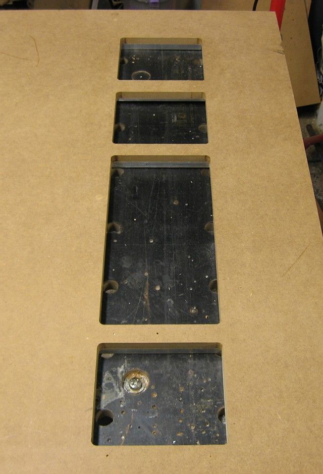
The aluminum bits were removed and the particle board template was used to cut the .10-inch thick aluminum sheet.
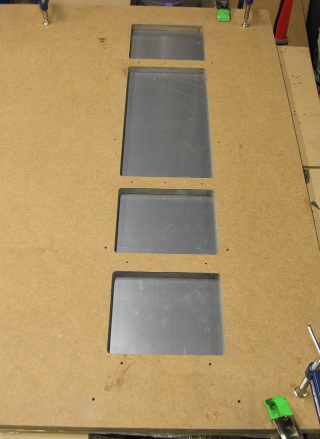
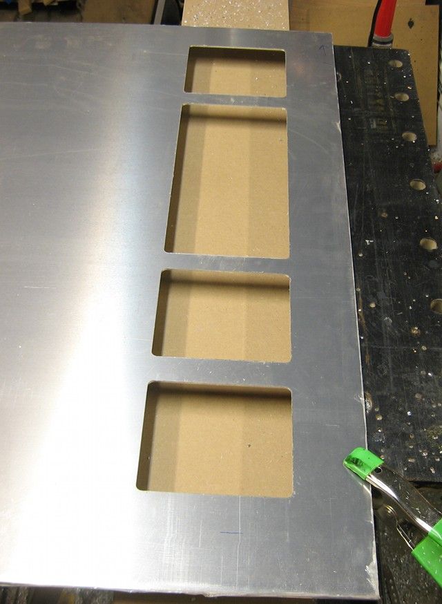
Now I just need to square all of the corners and cut to width. Ugh.
In order to cut-out all of the openings for the 5.25-inch drives accurately, a custom router template is required. I used .5x1-inch u-channel and .25x1.25-inch flat bar to frame the openings on .5-inch particle board.
The aluminum bits guided my flush trimming router bit.
The aluminum bits were removed and the particle board template was used to cut the .10-inch thick aluminum sheet.
Now I just need to square all of the corners and cut to width. Ugh.
86 5.0L
Supreme [H]ardness
- Joined
- Nov 13, 2006
- Messages
- 7,085
i love your work
Stevennoland
Limp Gawd
- Joined
- Jan 5, 2006
- Messages
- 418
Yea, filing corners to sharp is a PITA! I try and engineer my builds to eliminate or minimize them. Your project is ambitious. Keep up the good work!
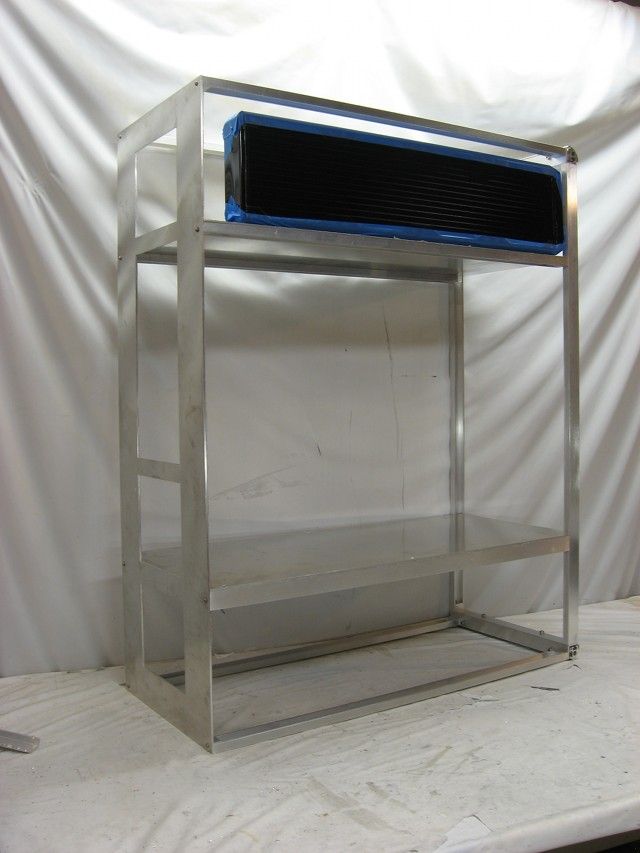
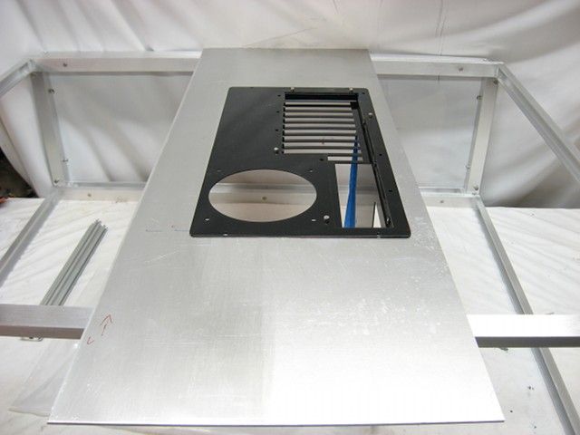
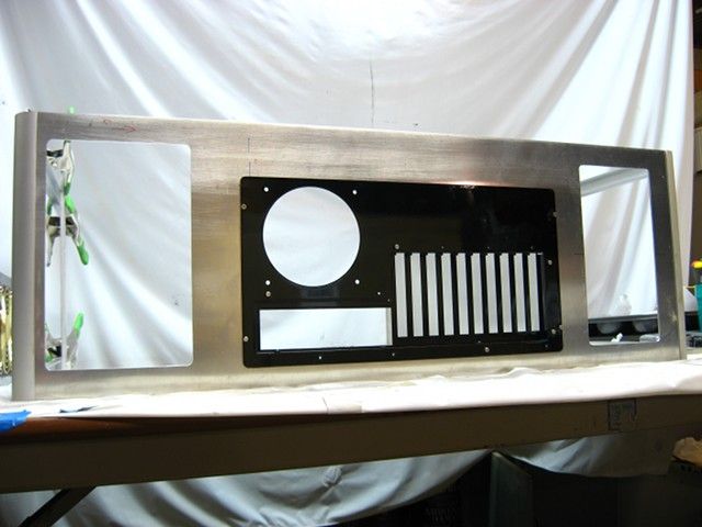
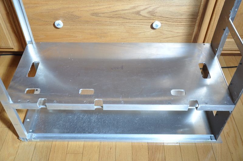
Two cutouts were routed out of the back sheet for the bottom mounted PSU (left hand side of the pic) and intake fan, and two intake fans up top.
Eventually, some "adapter plates" will be mounted over the two cutouts.
To attach the MB tray to the back sheet, four PEM cinch nuts were pressed into the interior side of the .10-inch thick aluminum sheet. I love these nuts because they make quick work out of adding some threads to sheet metal.
Eventually, some "adapter plates" will be mounted over the two cutouts.
To attach the MB tray to the back sheet, four PEM cinch nuts were pressed into the interior side of the .10-inch thick aluminum sheet. I love these nuts because they make quick work out of adding some threads to sheet metal.
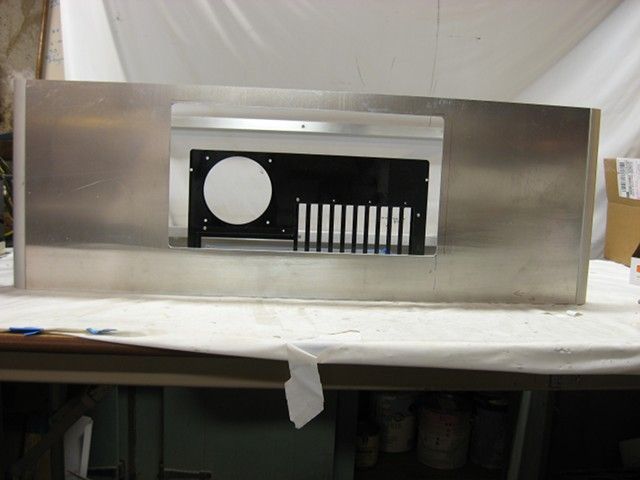
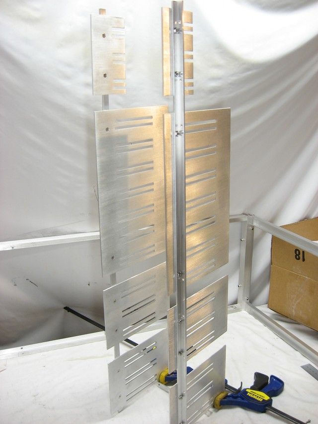
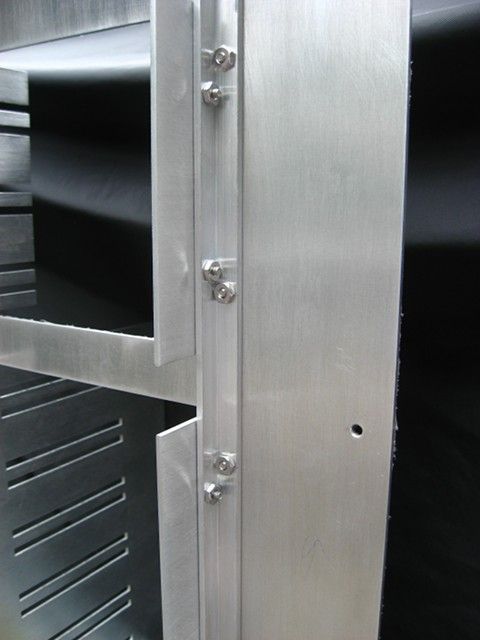
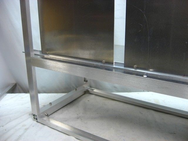
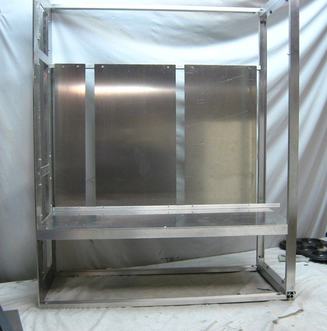
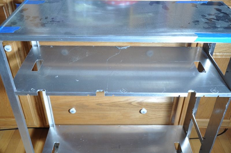
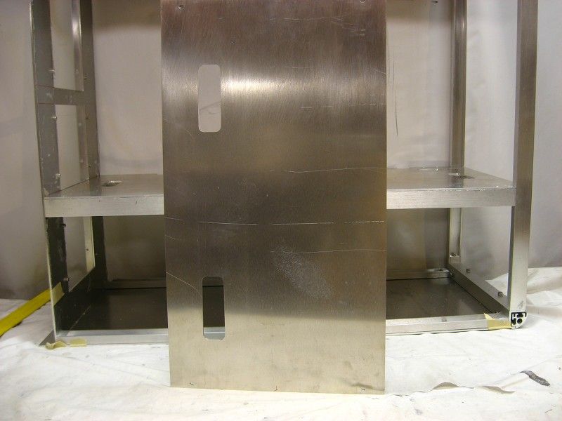
Another awesome feature of this case is the "false" back, which is simply a sheet of aluminum between the removable back panel and the motherboard tray. The "false" back prevents the case from racking and is the primary cable management feature. In this case, the "false" back consists of three pieces of .10-inch thick aluminum.
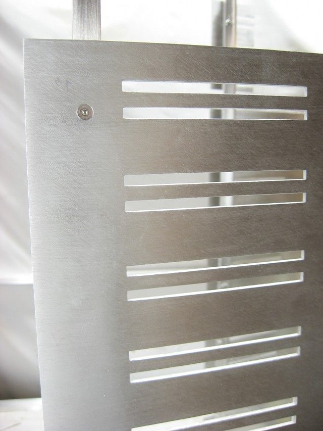
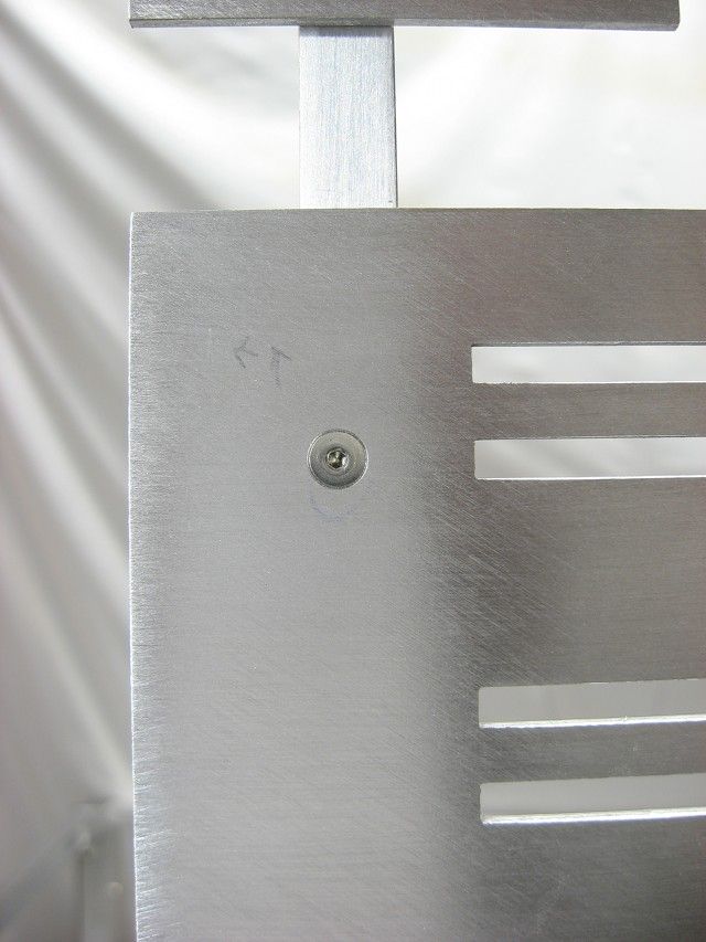
The sheets that make-up the "false" back are threaded along the top via PEM nuts. Fastening them to the top support beam is simplified via the addition of slots routed out of the support beam. These allow the hex wrench to be raised into position as the socket cap screws are driven into the sheet.
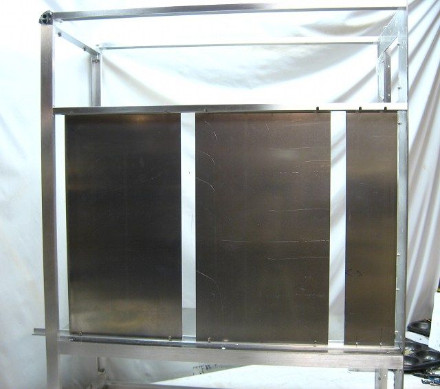
Along the bottom, the sheets are fastened to some 1/2-inch angle.
The sheets that make-up the "false" back are threaded along the top via PEM nuts. Fastening them to the top support beam is simplified via the addition of slots routed out of the support beam. These allow the hex wrench to be raised into position as the socket cap screws are driven into the sheet.
Along the bottom, the sheets are fastened to some 1/2-inch angle.
wra18th
[H]F Junkie
- Joined
- Nov 11, 2009
- Messages
- 8,492
It's getting there. This looks to be an awesome case. Can't wait to see it finished.
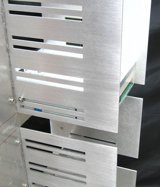
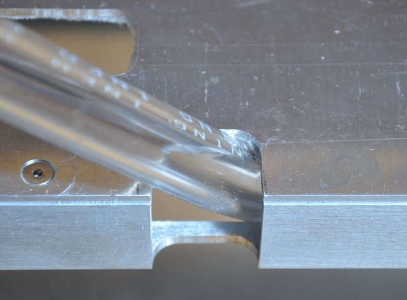
Slots for wire and tube routing were cut out of the top and bottom shelves. I attempted to use a pattern router bit, but the deep cut forced the bit's bearing into the 3/8-inch thick particle board, ruining it.
So I switched to using a pattern to guide the base of the router.
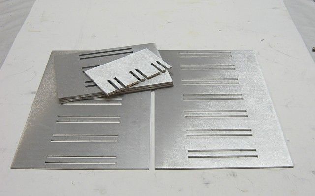
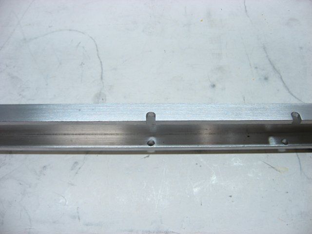
The slots along the edge of the bottom shelf were cut in such a way to allow tubing and wiring to pass without significantly weakening the 1/2 x 1-inch u-channel.
Bottom shelf slots:
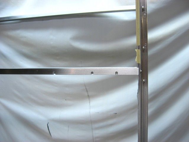
Top shelf slots:
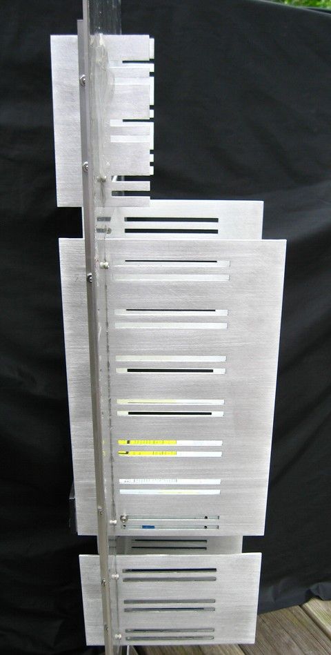
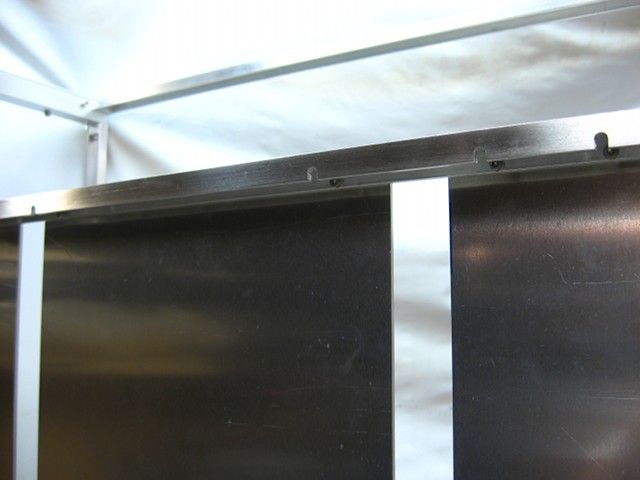
Finally, two slots were also cut out of a portion of the "false" back:
So I switched to using a pattern to guide the base of the router.
The slots along the edge of the bottom shelf were cut in such a way to allow tubing and wiring to pass without significantly weakening the 1/2 x 1-inch u-channel.
Bottom shelf slots:
Top shelf slots:
Finally, two slots were also cut out of a portion of the "false" back: