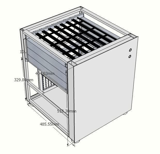
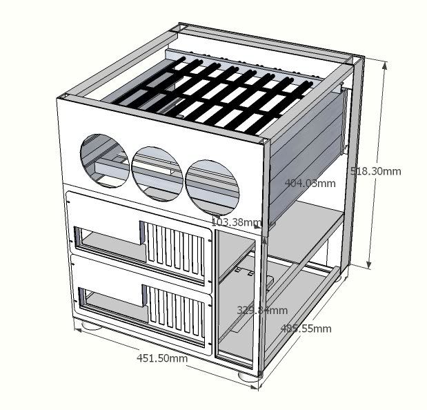
This is a project/build log for a custom case to house both a storage server and gaming rig.
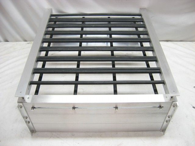
This fairly compact case is designed to hold:
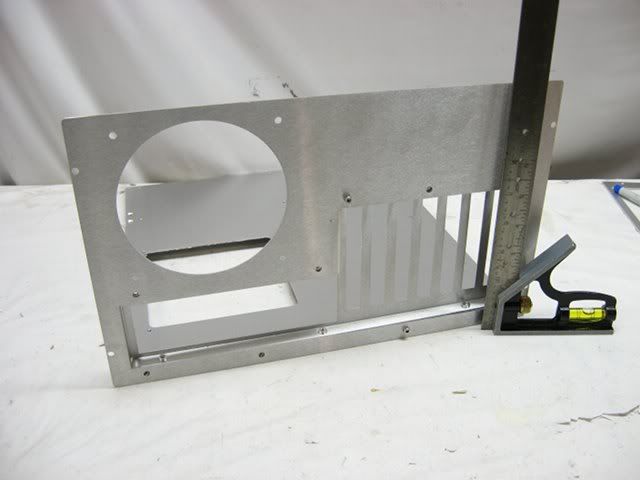
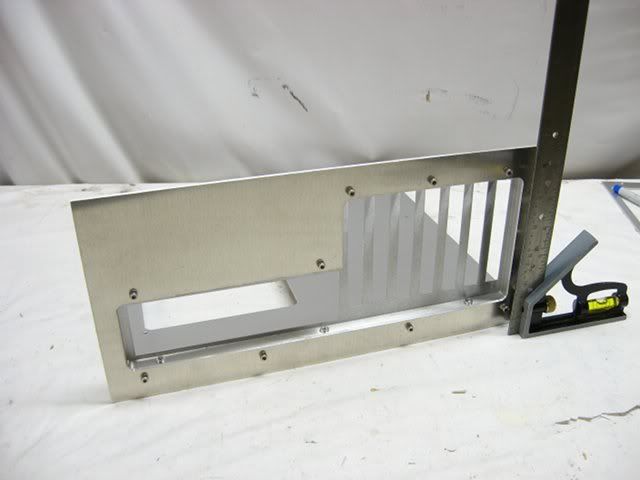
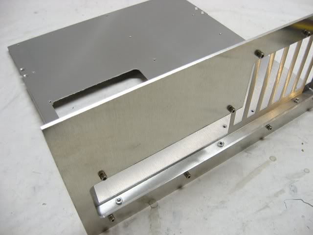
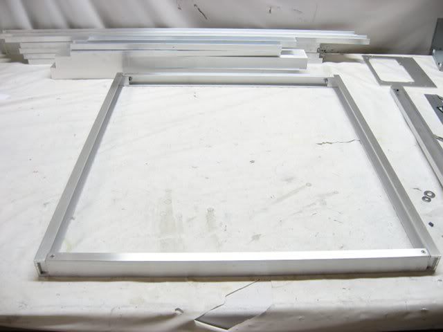
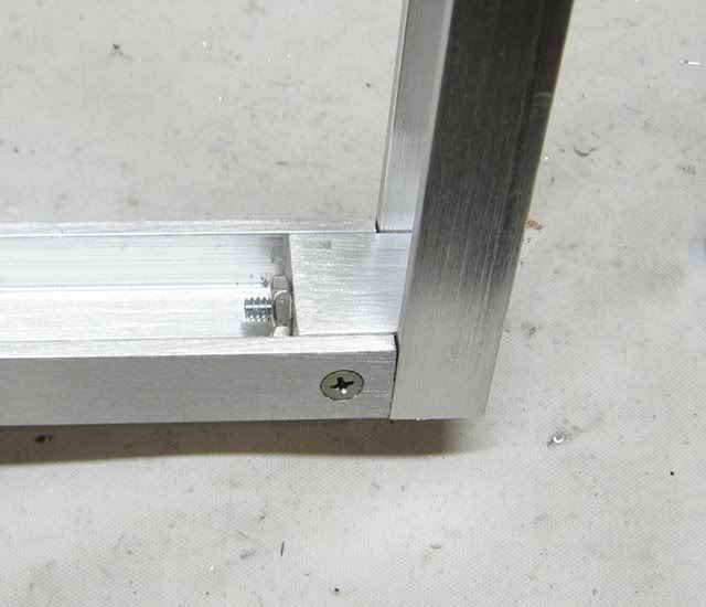
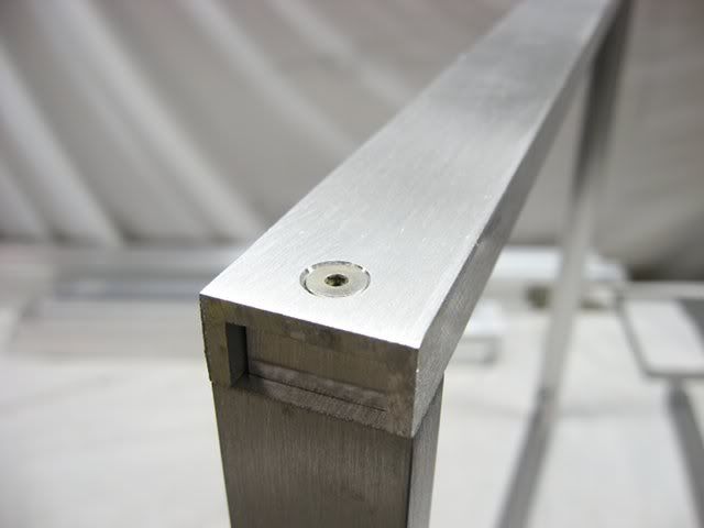
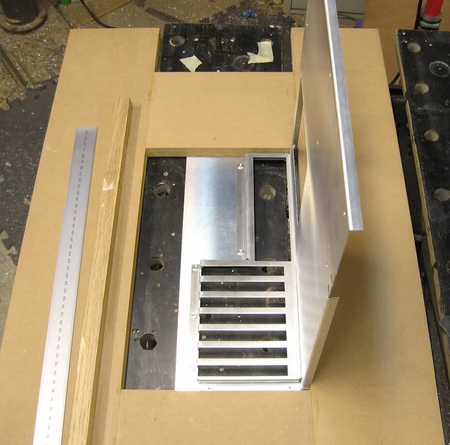
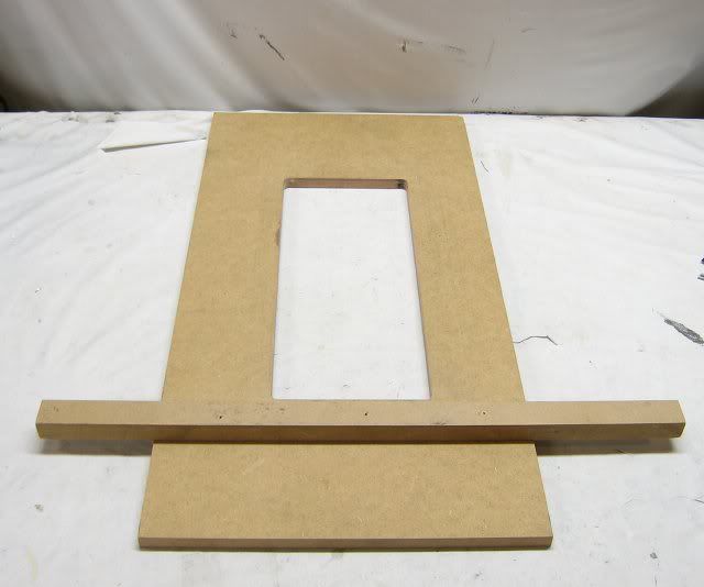
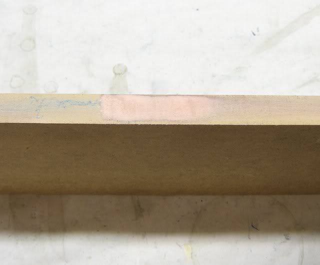
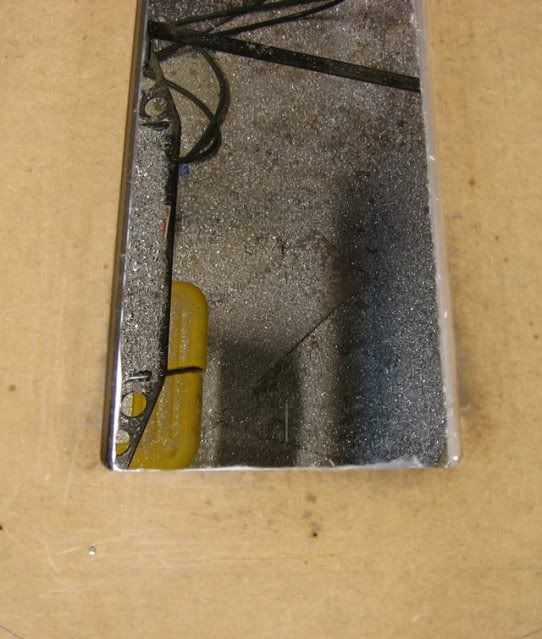
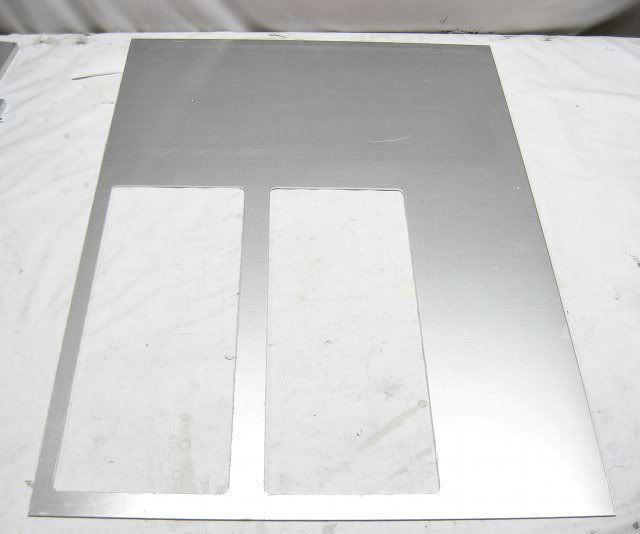
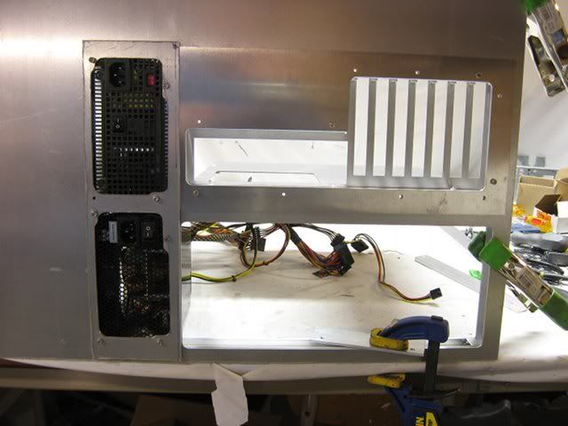
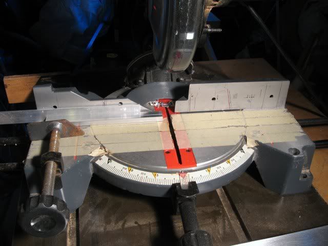
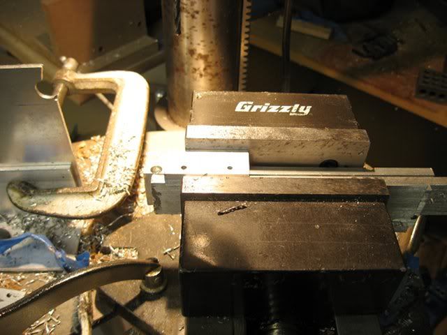
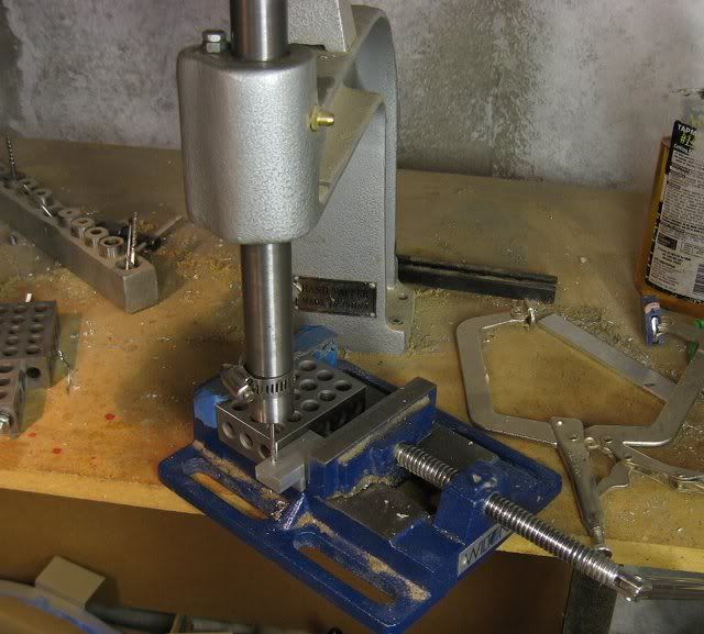
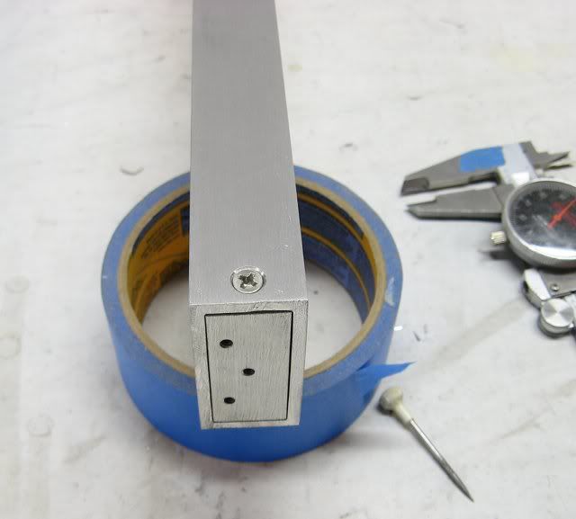
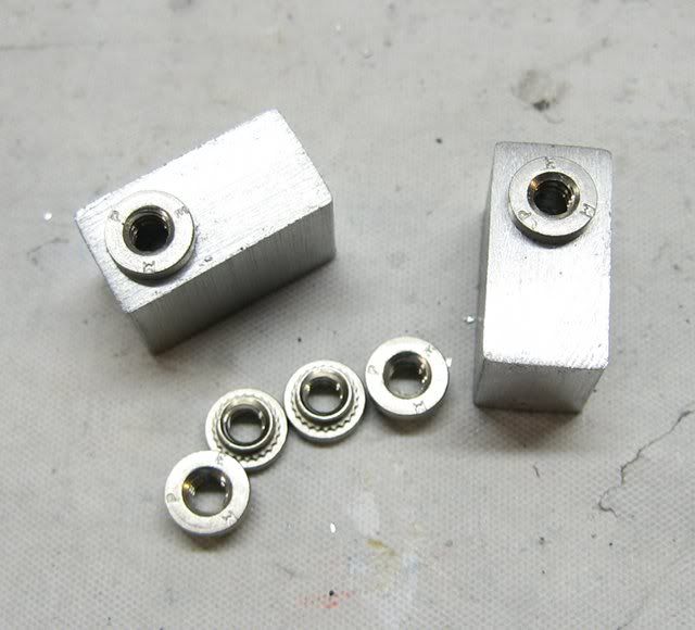
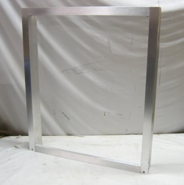
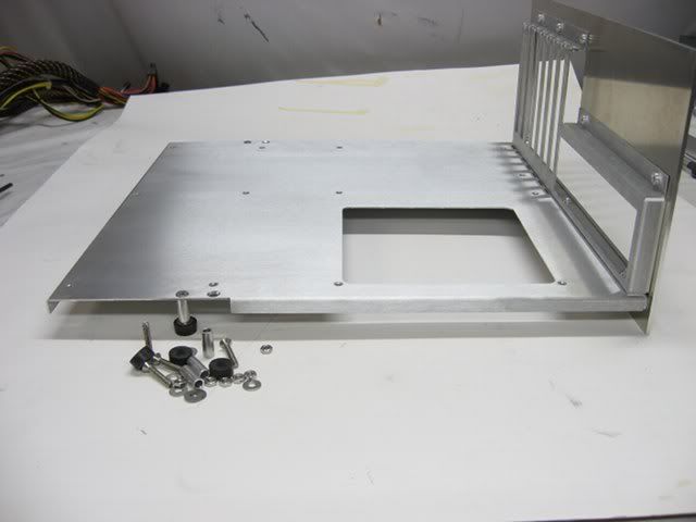
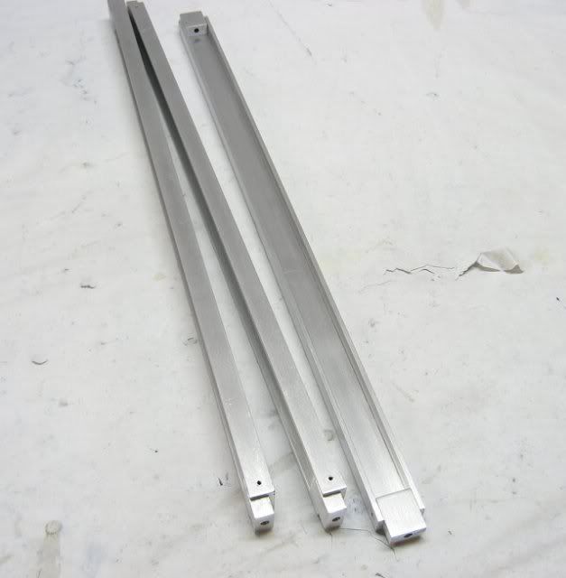
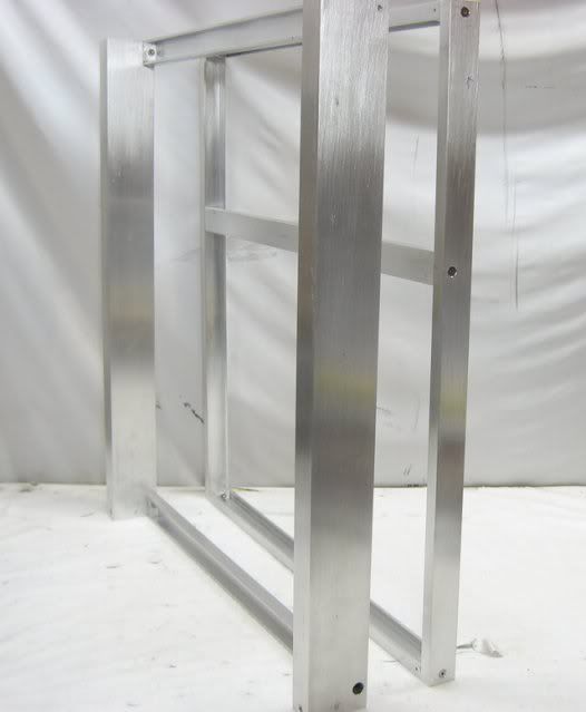
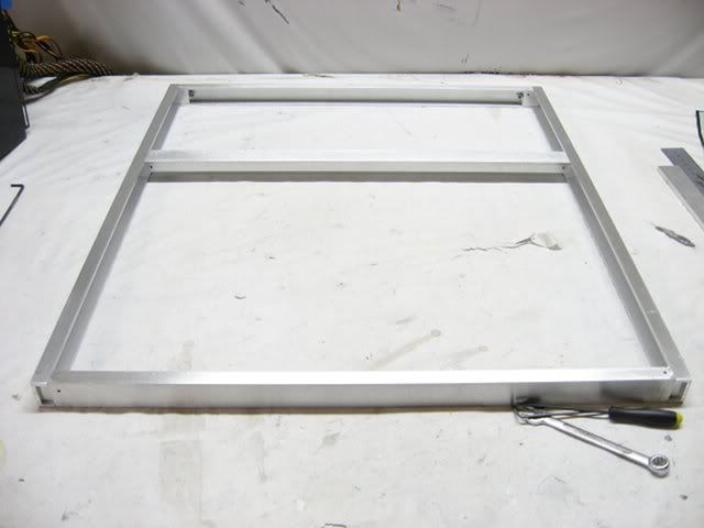
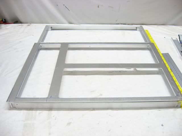
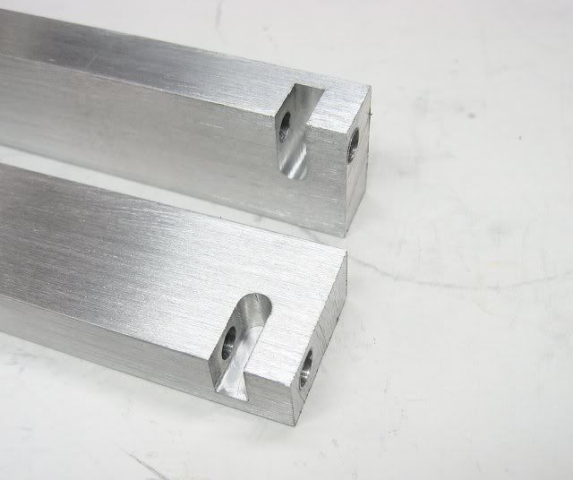
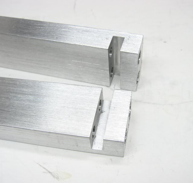
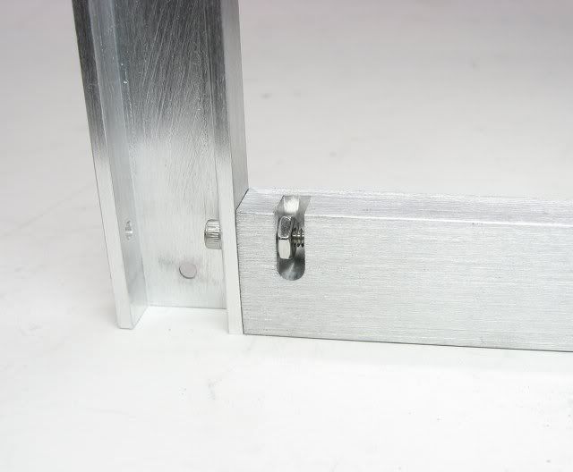
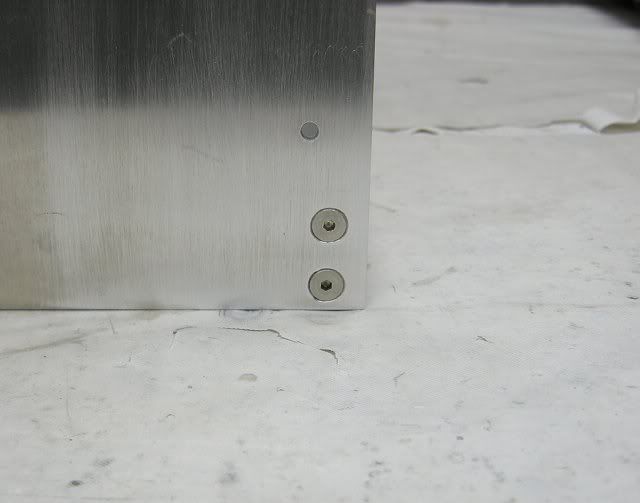
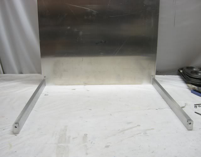
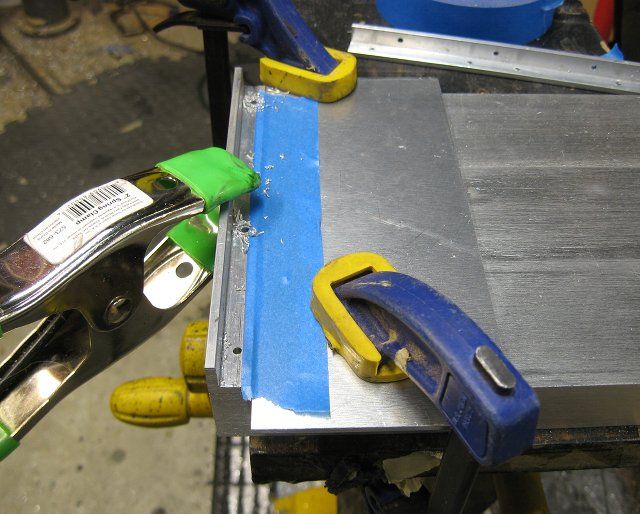
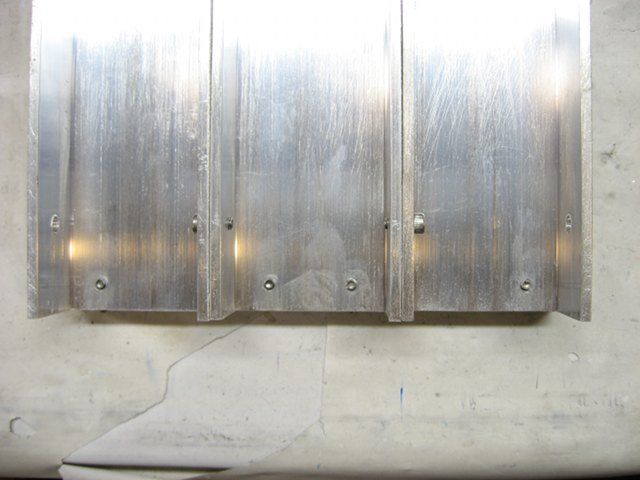
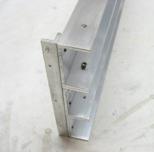
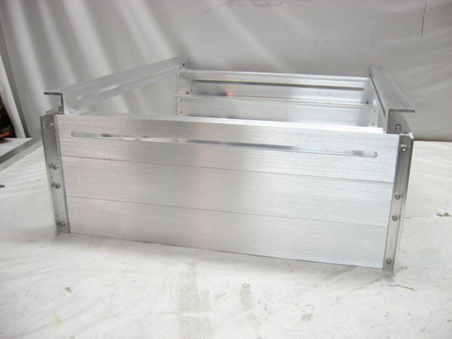
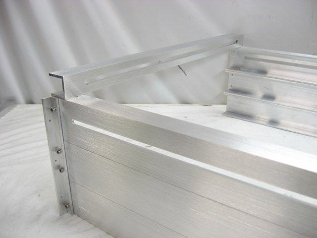
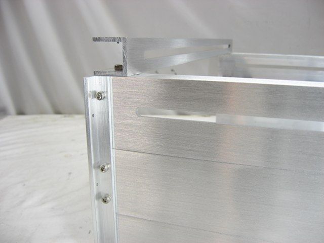
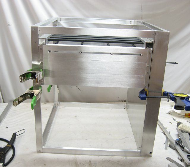
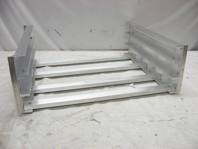
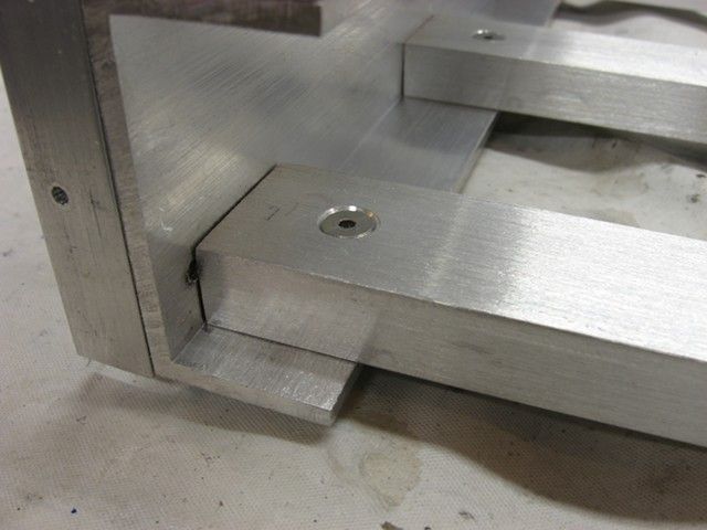
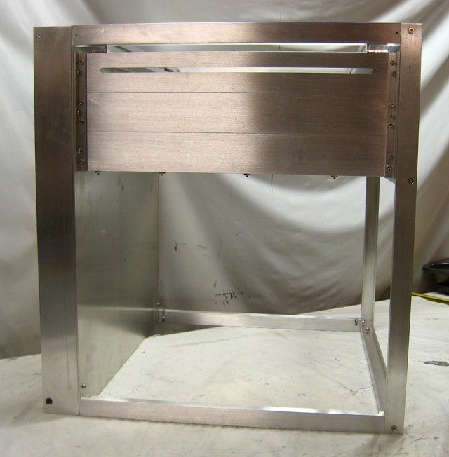
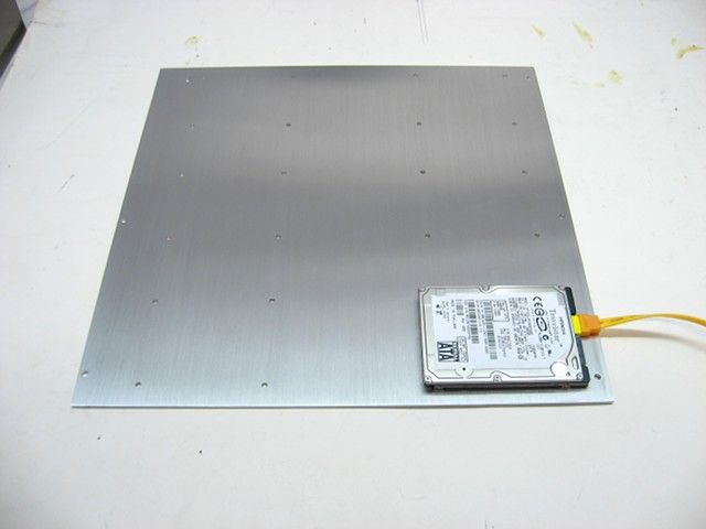
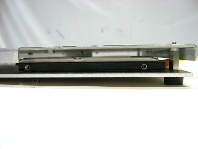
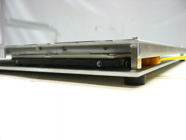
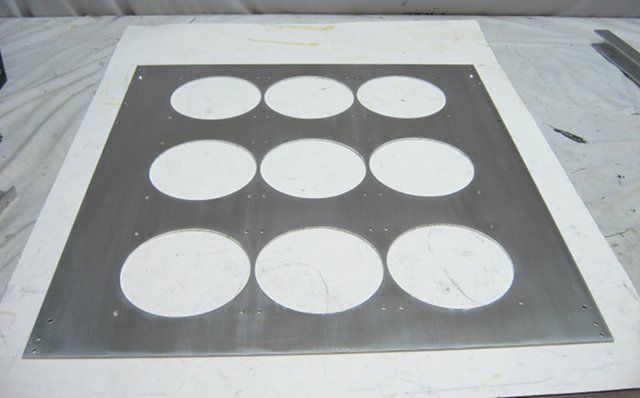
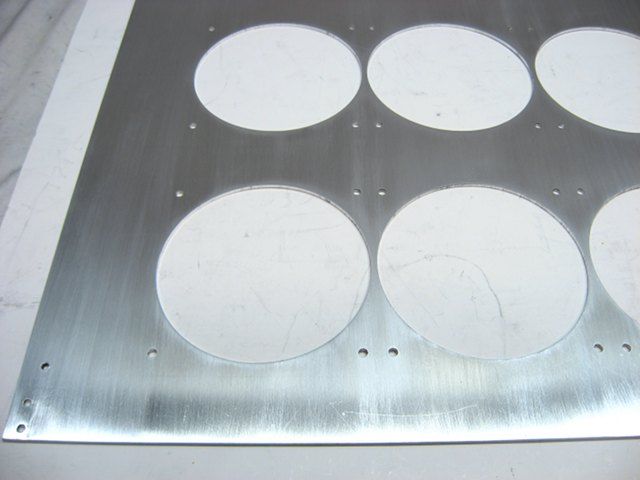
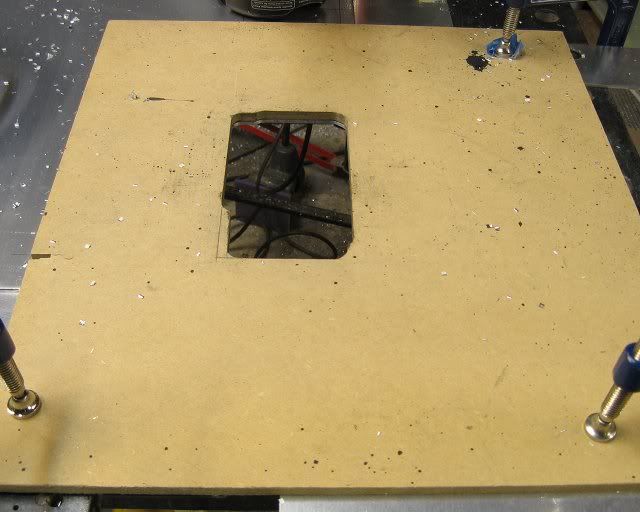
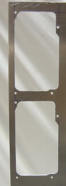
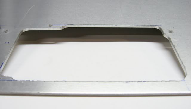
The size of the case is to be kept as small as possible, which is mostly driven by the size of the motherboard trays. But until those arrive, I fabricated the PSU mounting plate from some 2.5mm aluminum sheet.
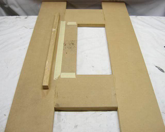
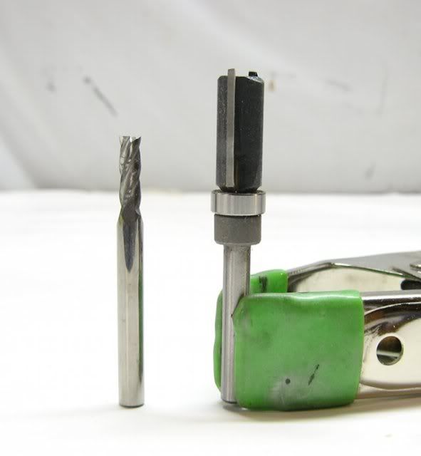
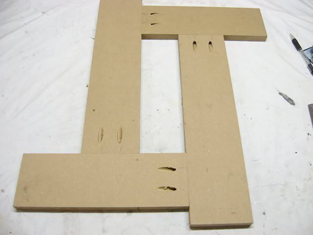
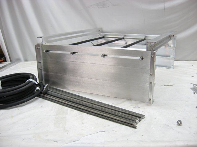
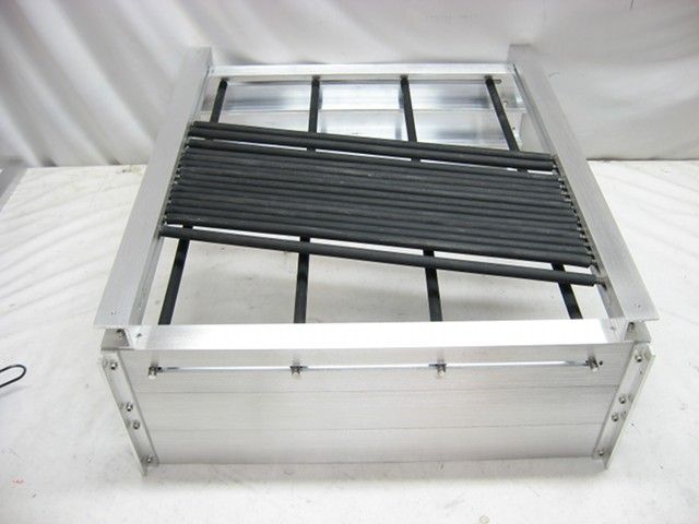
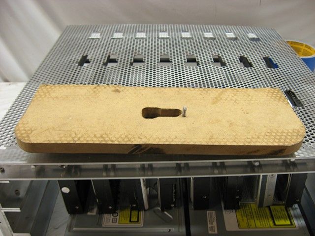
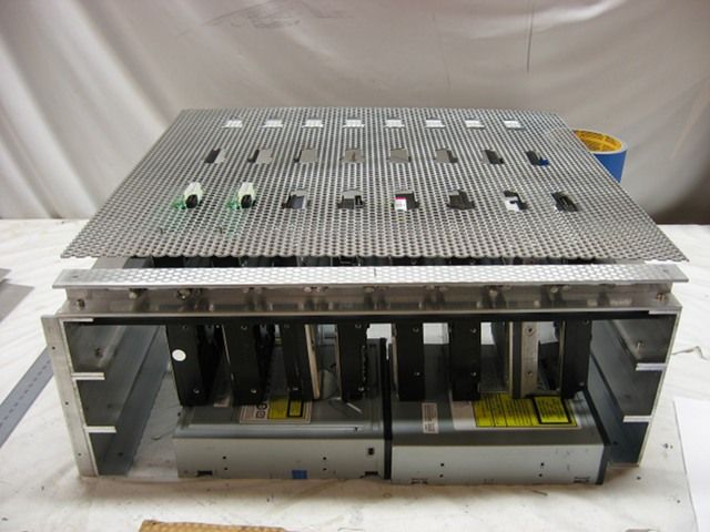
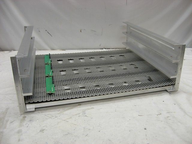
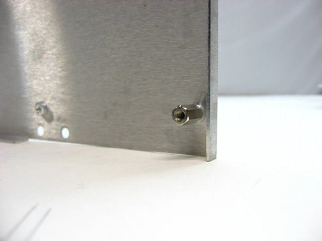
The cutouts were made via a hand held router fitted with a flush pattern bit, guided by a template.
That's it for now!
This fairly compact case is designed to hold:
- Two EATX motherboards
- Two ATX PSUs
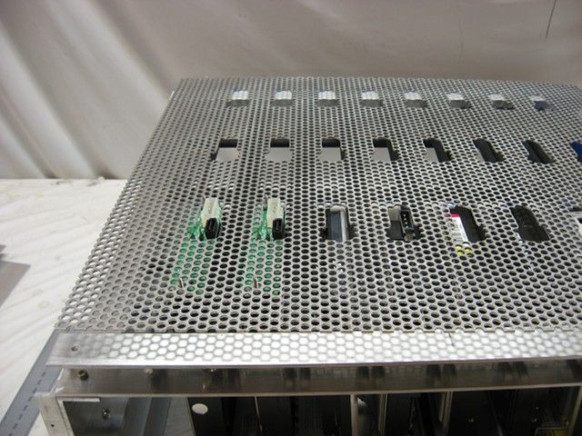
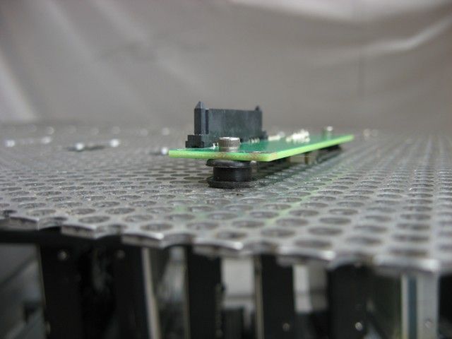
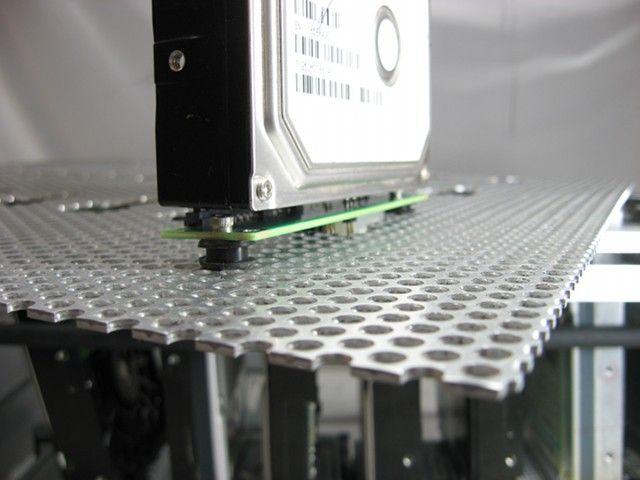
- Twenty four 3.5-inch hard drives
- Six SSDs
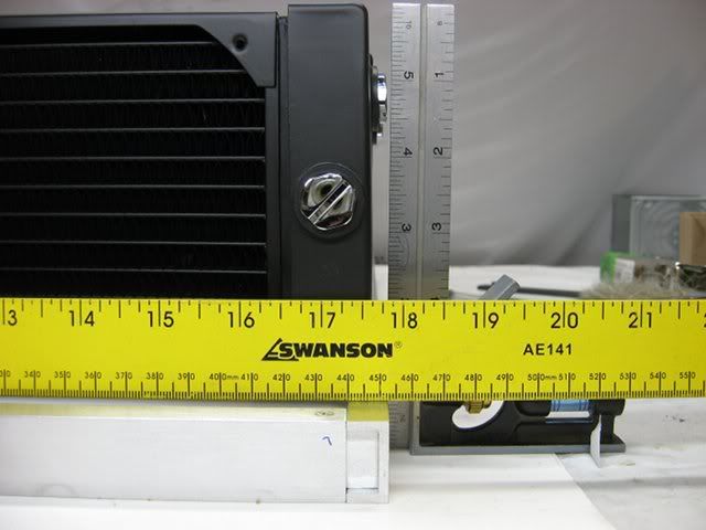
- Two 120x3 water cooling radiators
The size of the case is to be kept as small as possible, which is mostly driven by the size of the motherboard trays. But until those arrive, I fabricated the PSU mounting plate from some 2.5mm aluminum sheet.
The cutouts were made via a hand held router fitted with a flush pattern bit, guided by a template.
That's it for now!
")