ekuest's Mobile Desktop

ekuest

Supreme [H]ardness
Joined
Feb 23, 2009
Messages
6,094
This project has been in the works for about 1.5 years now. I started out making a normal water-cooled ATX case back then, but quickly decided that it was boring. Over the next year I watched the rise of ITX, and finally had the means to build the computer I really wanted. Over the last 6 months, I've amassed the following components for this build:

CPU: Intel Core i7-860...........................................................................$160 used
Mobo: Gigabyte GA-H55n-USB3............................................................$110 new
RAM: G.Skill Sniper 2x4GB DDR3 1333, 9-9-9-24, 1.5V.............................$75 new
GPU: Sapphire HD5870 1GB.................................................................$215 new
HSF: Thermalright AXP-140+Yate Loon Medium Speed 140mm Fan............$62 new
HDD: 320GB Seagate Momentus 7200.4...................................................$30 used

Total...................................................................................................$652

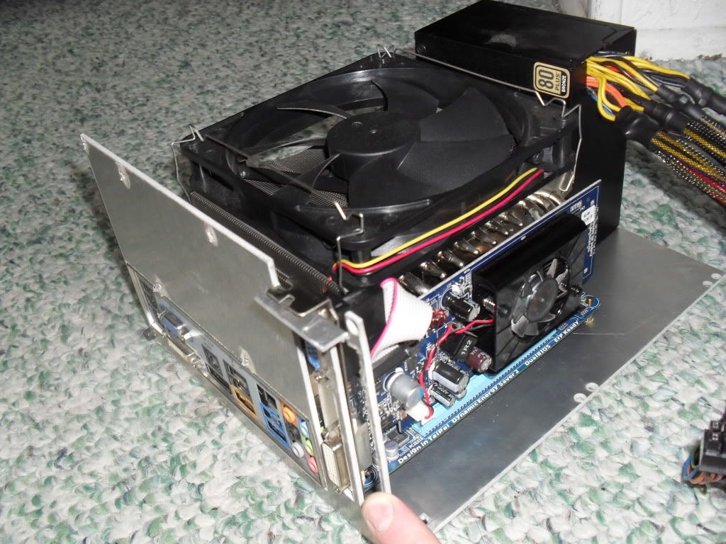
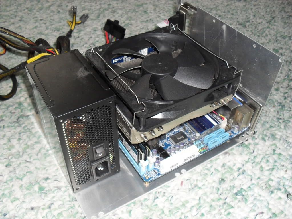
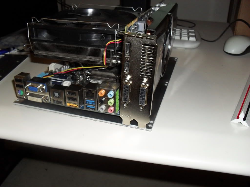
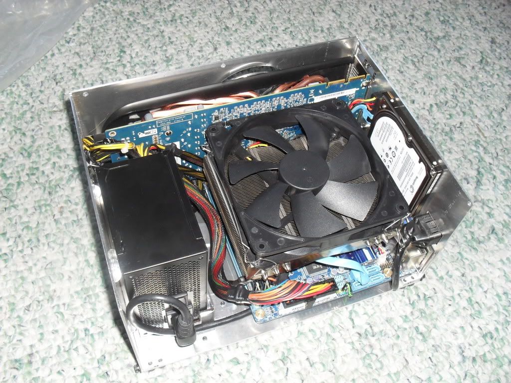
Why I decided on these components: I change my mind a lot and upgrade regularly, so I wanted to make it able to fit whatever I am currently using. With the rise of ITX complete, I figure I can plan on always finding a mini-ITX motherboard to my liking. For the gpu I wanted to fit anything up to 10 inches, since typically any cards longer than 10 inches require way too much power for my PSU. That brings me to my PSU, which is SFX. ATX PSUs are just too big, and would have made my case much bigger than I wanted. The largest SFX PSU is the SIlverstone ST45SF, which puts out healthy 432W on the +12V rail. This gives me plenty of room to run my 5870 and a 95W quad-core CPU, since I will be undervolting the CPU. The only thing im worried about is fitting my HSF on future ITX motherboards, but I should be able to use any smaller heat sink, or even the stock one, just fine since the CPU will be undervolted.

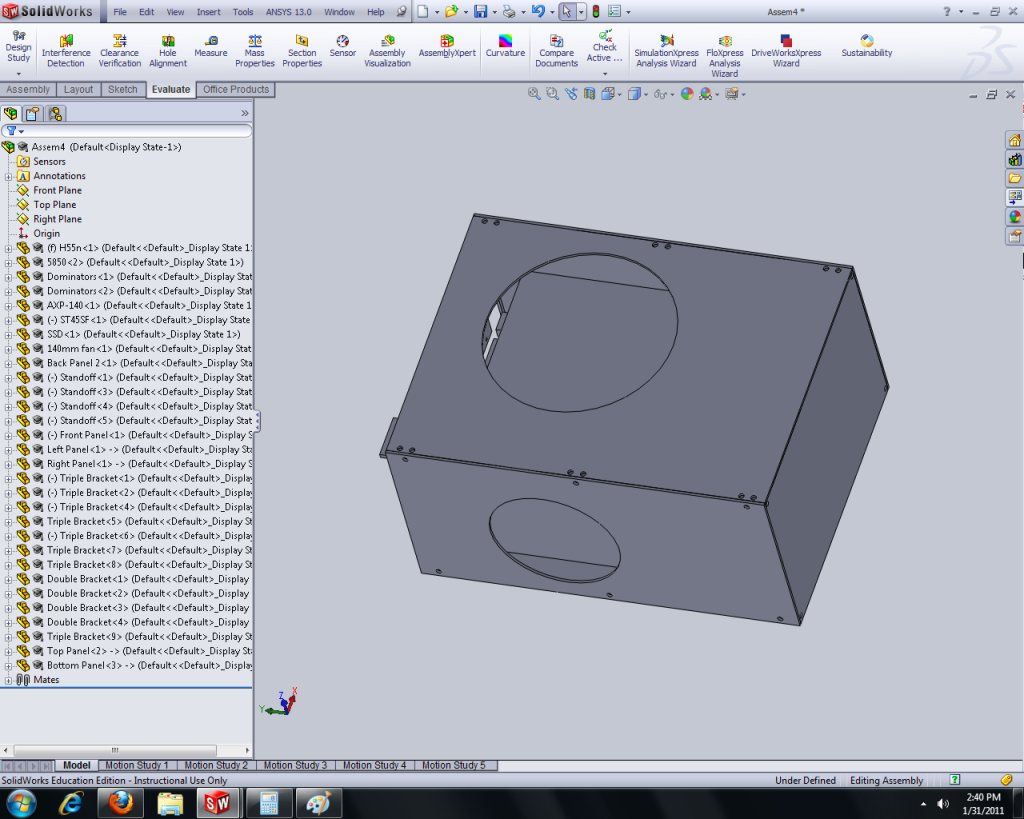
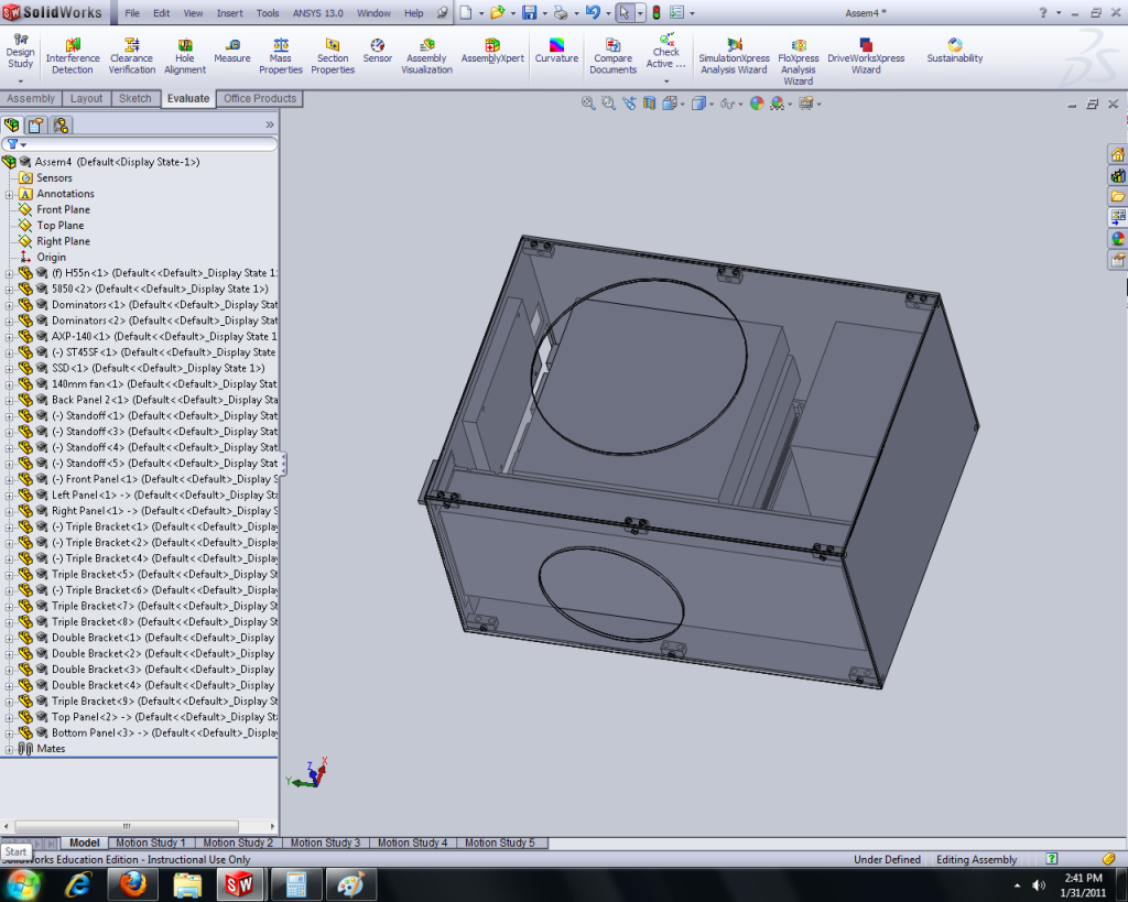
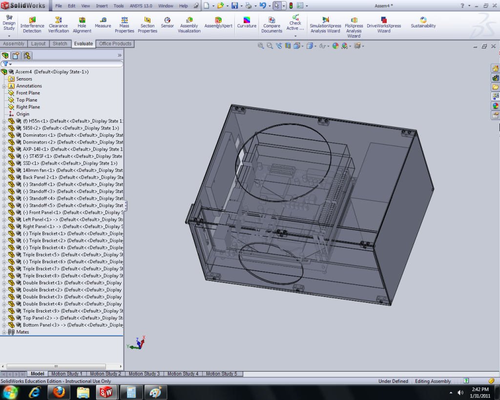
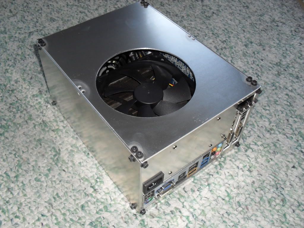
The case design: Once I decided on the components, I positioned everything in a 3D modeling program called Solidworks, and found the smallest case I could make. Since I wanted the case to last, I decided to make each panel (6, for a rectangular prism shape) modular, and able to be taken apart and put together in any order I wanted. This would allow me to add ports, change vent locations, even make a specific back panel for every new motherboard to fit its particular port arrangement (although i decided to forgo that idea this time around), etc. So, because I don't care for photoshop or photography or even writing more words that people won't read, I will just get right into it.

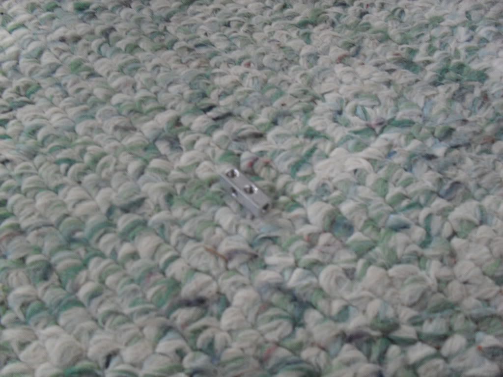
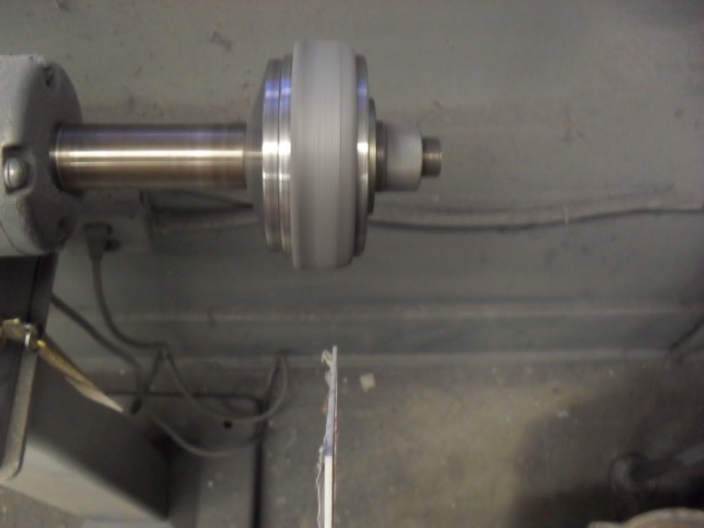
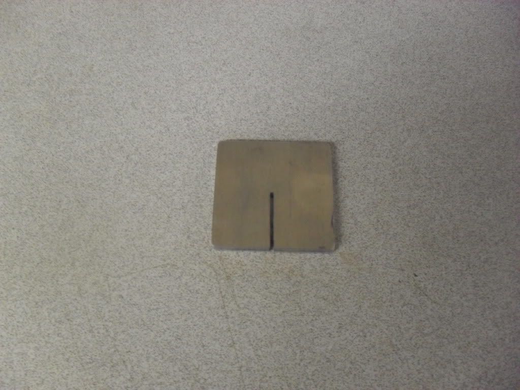
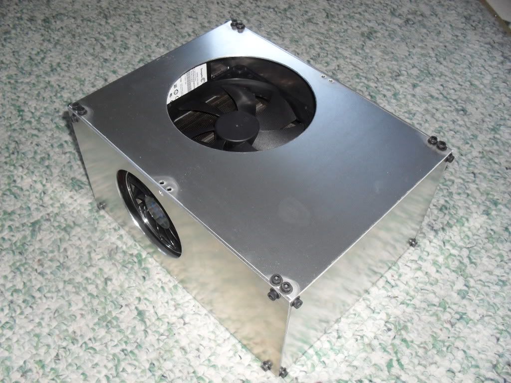
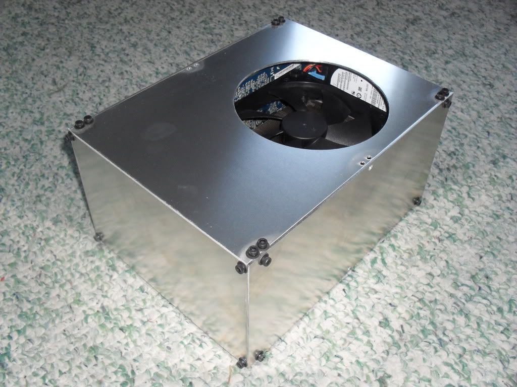
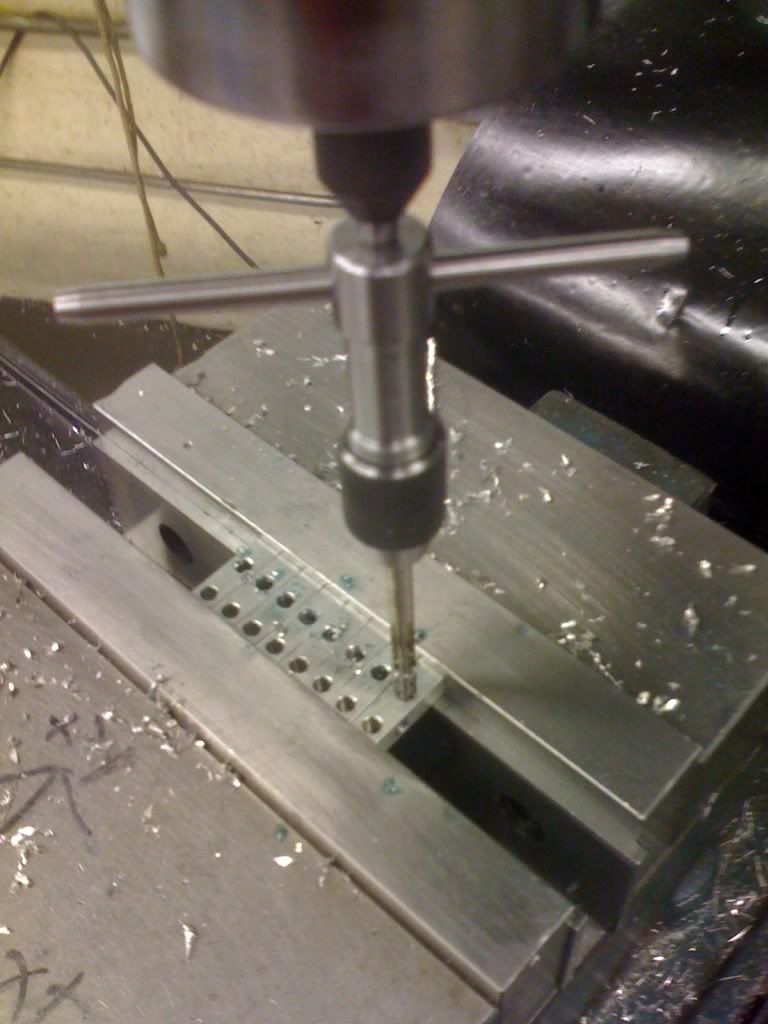
First I made all these way cool corner pieces which will hold all the panels together, one in each corner.
IMG_0513.jpg


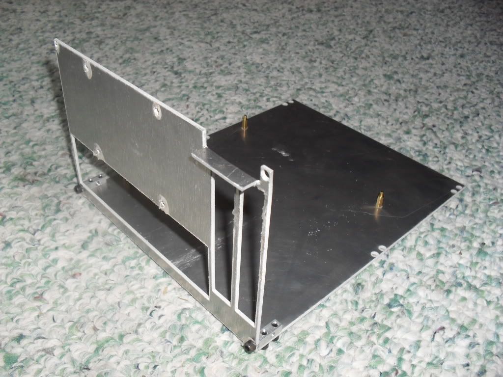
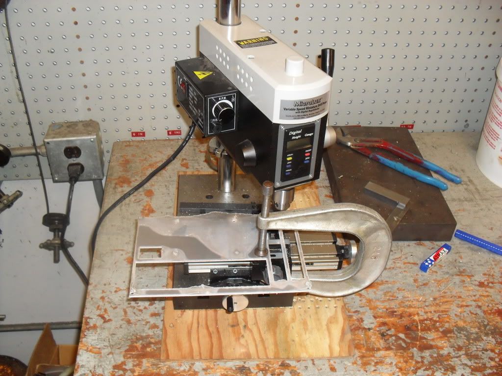
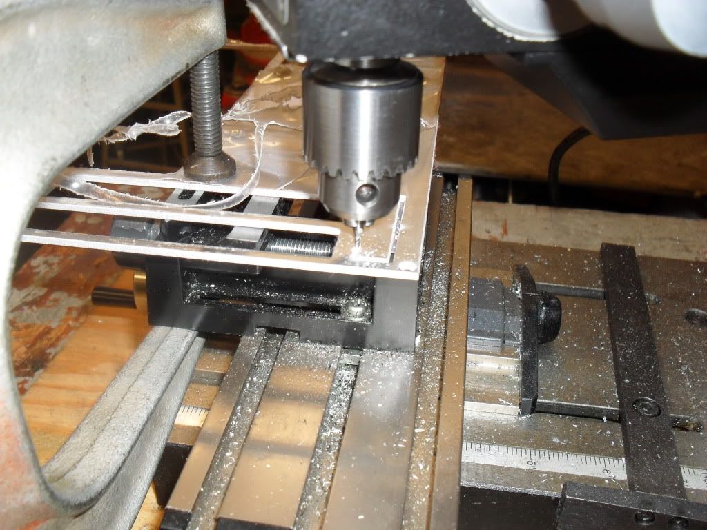
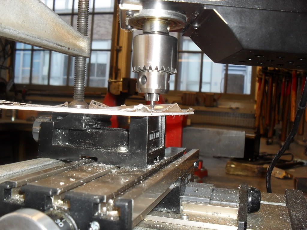
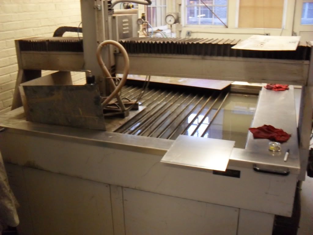
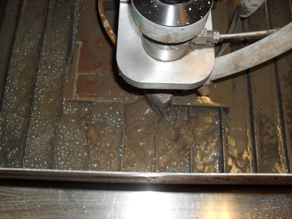
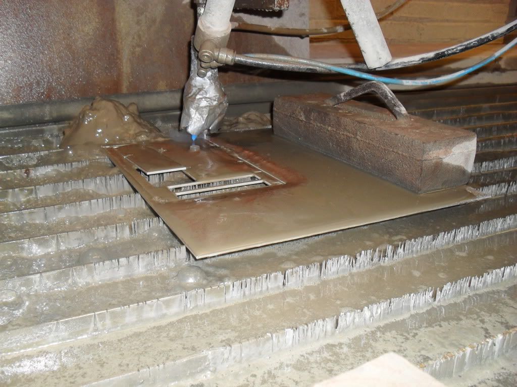
Then I cut out the first two panels on a water jet machine since its way easier and more precise than doing it by hand.
SDC12048.jpg


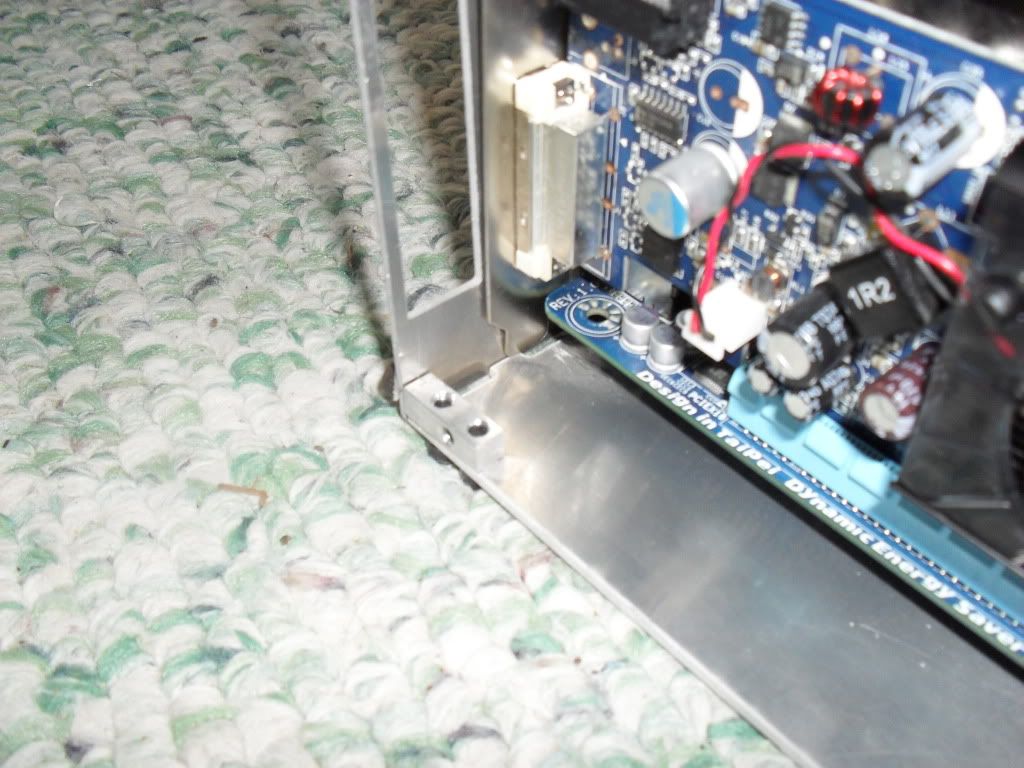
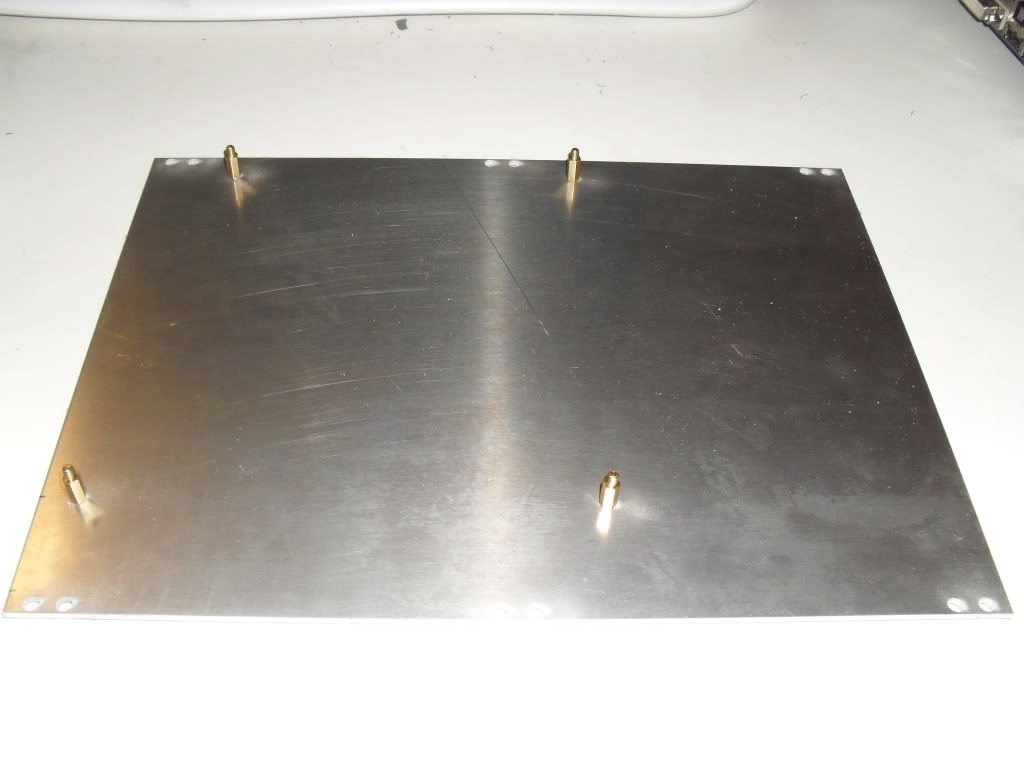
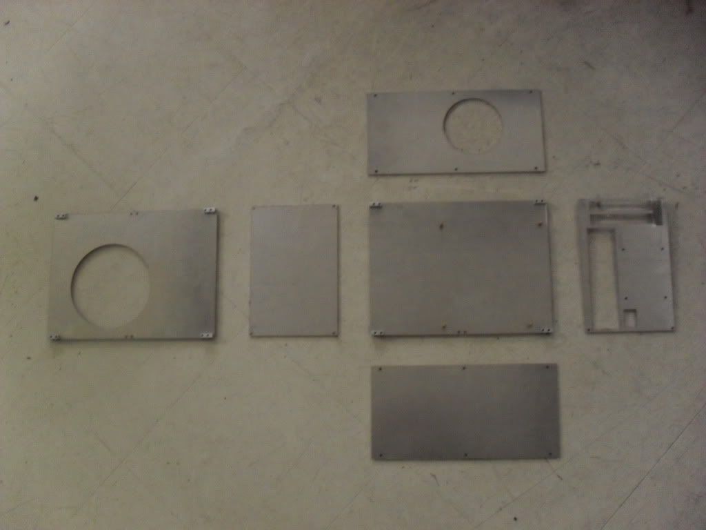
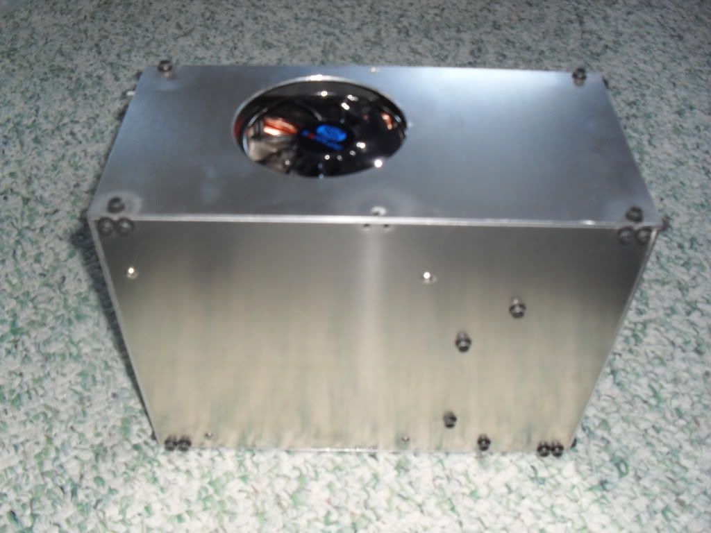
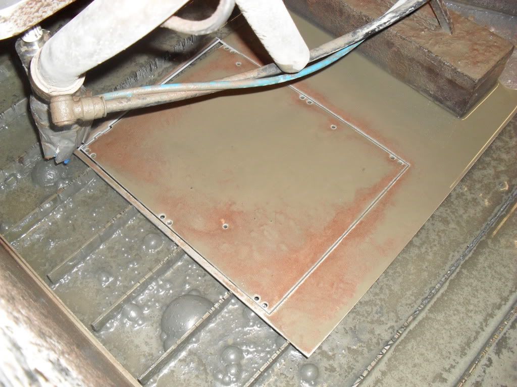
Bottom Panel. If you'll notice, there's about 1/16" between some of the holes and the nearest edge of the panel.
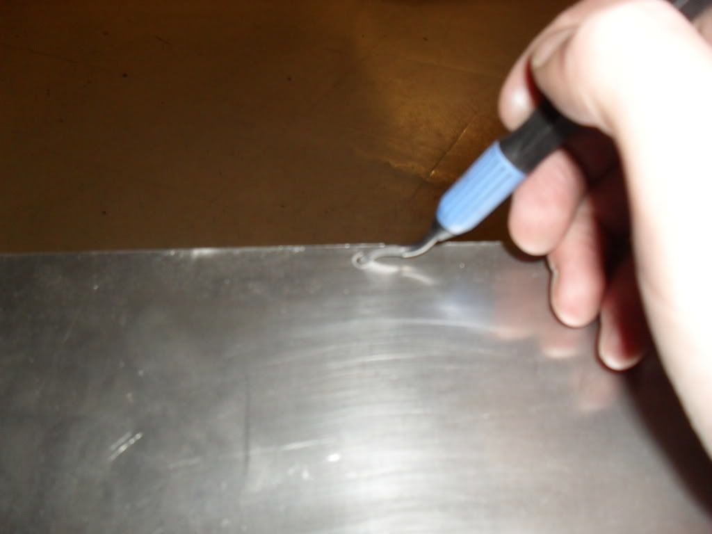
SDC12050.jpg


Bubble
SDC12054.jpg


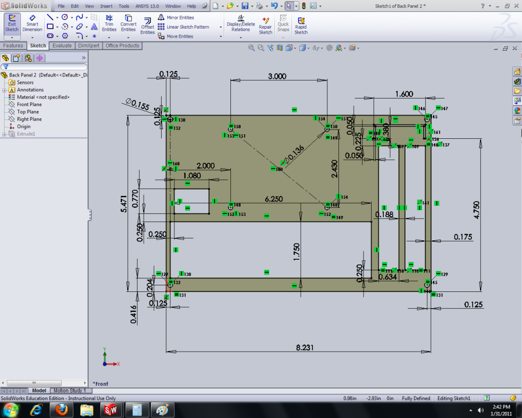
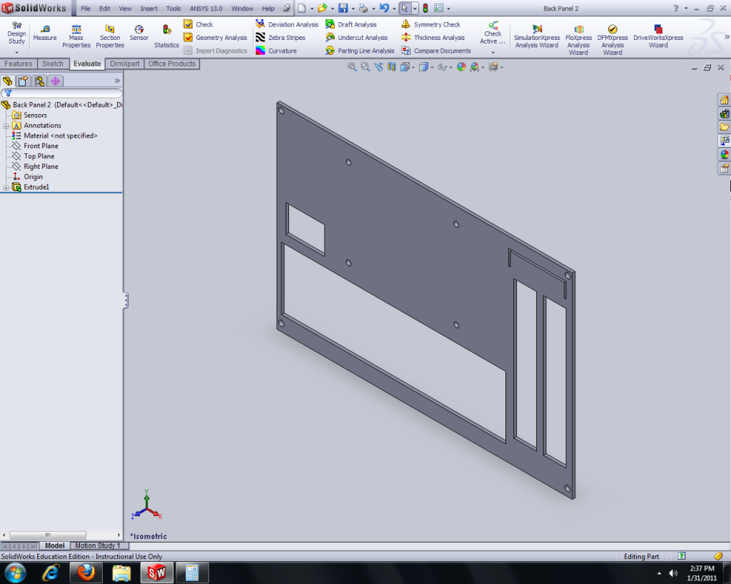
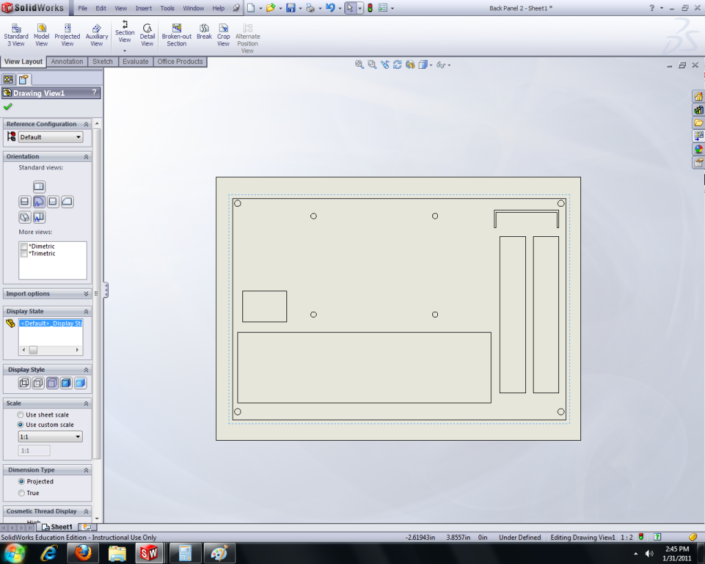
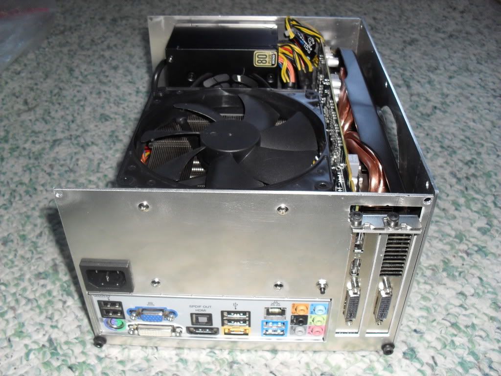
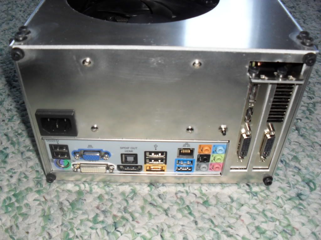
Rear Panel, with I/O shield space and the PCI slots.
SDC12057.jpg


Is it easier if I do big pics like this so you don't have to click links, or would you rather have thumbnails so the page loads faster and you can click for big?
 
I like it as is :D (photo size)

Thank you for the work log!! :) Definately bookmarked
 
I like it as is :D (photo size)

Thank you for the work log!! :) Definately bookmarked

thanks jeremy! ive been following your redux mod since you started as you know. SFF always gets me, especially water cooled SFF. :D
 
Intriguing build. Images are perfect how they are as well.

ok thanks, i'll keep them big.

Interesting, will follow along.

thanks!


ok so i have some first fit pictures here. i had to guess on a few things, since I RMAd my 5870. i think the heatpipes on the AXP-140 might have shorted out one of the caps on my card. :/ also, i shortened the case right before i made these first 2 pieces, and the card that i was using in the 3D model was a 5850, not a 5870, so i may have made it too short. i should get the rma back today or tomorrow so i'll know soon if i messed up.

heres a picture of one of the corner pieces
SDC12062.jpg


this is a picture of the first two panels attached together. the shop master who did the computer part while i prepped the machine missed one hole when he was selecting profiles, so there are currently only 3 motherboard standoffs. ill have to drill the last one by hand
SDC12059.jpg


heres a nice big pic of everything. note that cane-shaped thing off to the right, it has a very important purpose. can anyone guess what that might be for bonus points? also bonus points to anyone who manages to find it again in future photos. :)
SDC12063.jpg


heres one screw-up. the bottoms of the cards are supposed to go through these little slots, not get hung up on them. ill just mill out the middle space next time im in the shop.
SDC12065.jpg


and the other screw-up is that the bent part for the pci brackets to screw into might be a little low. i had to eyeball this, and i think if i can fix the other screw-up, then the card should sit a little lower and this gap will shrink a bit.
SDC12066.jpg


and heres a pic of the other side of the computer. the power cord will route to the back panel with an extension cord im making.
SDC12067.jpg


any questions or comments, feel free to post! also, i just got my security clearance yesterday, and i will be moving to hawaii in a week or two to work in the shipyard. that means i now have a deadline for this project! :eek:
 
Last edited:
ok so i have some first fit pictures here. i had to guess on a few things, since I RMAd my 5870. i think the heatpipes on the AXP-140 might have shorted out one of the caps on my card. :/ also, i shortened the case right before i made these first 2 pieces, and the card that i was using in the 3D model was a 5850, not a 5870, so i may have made it too short. i should get the rma back today or tomorrow so i'll know soon if i messed up.

any questions or comments, feel free to post! also, i just got my security clearance yesterday, and i will be moving to hawaii in a week or two to work in the shipyard. that means i now have a deadline for this project! :eek:

The HD5870 is about 1" longer, iirc. Mostly becaues the PCIe plugs are up top, so the +.6" otherwise isn't a factor, I think.... I sold off my HD5870 ref and gave my HD5850 ref to my friend for his birthday, lol.

On #2.... I guess we both has serious schedules to meet, lol. Congrats on your move! :)

well this is the sapphire non-reference 5870, which is the same pcb as the sapphire non-reference 58XX cards i think, even the vapor-x and toxic models. and the connectors are on the end instead of the top. my rma wont get back till thursday according to ups tracking, so i guess i wont make any more progress till then. :/

EDIT: according to this review, sapphires custom PCB is 257mm, or just over 10in. plus the .5in for a power cable. and the 10in that i made the bottom is not going to be long enough. i will wait to lengthen it until i get my RMA so i can make sure its going to be long enough, but i think i'll make it 11in total just to be safe.
 
Last edited:
note that cane-shaped thing off to the right, it has a very important purpose. can anyone guess what that might be for bonus points? also bonus points to anyone who manages to find it again in future photos. :)

Pfft, easy, it's to check when your computer needs an oil change.
Unless I am Miss Taken, I see it in 2 pictures, providing some rigidity and the perfect archway to the fan cable on the PCI board.
A bit dangerous, though. Maybe replace the cables with solid copper ones. I know I would not be able to sleep thinking about all that bare metal... ^-^
 
Sorry, But I don't see any clip holding the fan wires. I do see two fan clips holding the fan to the heatsink, Looks like something Thermalright made.
 
I can't tell from these pictures, but could the cane device be for that pesky video card lock? Based on the way you have everything packed in there, I am thinking maybe you can't get your finger in there to release the video card from the mobo.
 
Cool project ekuest, looking forward to tagging along and seeing the final product[/QUOTE

glad to have you along!

sweet project and nice quality case.

yeah hopefully it'll be quality enough. i think the aluminum is thick enough that the exoskeleton design will be enough. even the langear mini-itx case has a bunch of interior frame parts, but i decided that was too much work and would take up too much room. only the finished project will show if this will be quality enough to withstand checked baggage on united. :)

Awesome project. I hope we all get to see it done in time.

haha me too! hopefully there will be some decent progress today.

Pfft, easy, it's to check when your computer needs an oil change.
Unless I am Miss Taken, I see it in 2 pictures, providing some rigidity and the perfect archway to the fan cable on the PCI board.
A bit dangerous, though. Maybe replace the cables with solid copper ones. I know I would not be able to sleep thinking about all that bare metal... ^-^

nope this rig is air cooled, no oil needed! :) im not sure what youre talking about, as i cant find it in any other pictures here. only thing dangerous about this rig is those heat pipes right up against the back of the video card. but i put a piece of paper in there before, and ill try to find something a little more attractive for the final product. i assure you there are no exposed wires in this rig.

Sorry, But I don't see any clip holding the fan wires. I do see two fan clips holding the fan to the heatsink, Looks like something Thermalright made.

yeah those are the fan clips that came with the AXP-140. btw, anyone know how i could put a gutted fan on top of the 140mm fan to act as a shroud? i want it to lay right on top of the fan, but those fan clips are in the way... hmmmm.

I can't tell from these pictures, but could the cane device be for that pesky video card lock? Based on the way you have everything packed in there, I am thinking maybe you can't get your finger in there to release the video card from the mobo.

WINNER! there is no way to fit a finger in there unless i take out both sticks of ram, and at the rate i take my gpu out and put it back on, checking fit and all, its handy to have this thing readily available at all times. as shown here, its from the stock bracket, which was like 775 i think. i had to buy a 1156 adapter, so the old bracket was of no use to me, except this piece.

thanks for following along everyone. there should be a good deal of progress today. i got my 5870 back from rma yesterday, and had to both make taller and widen the case by about 1/2" and 1/8" respectively after some test fitting. my plan is to eventually upgrade to a 6970, which is almost 11", and has the power connectors on top. so the inside of the case is now 11" long. my 5870 is about 10.5, and the connectors are on the end, so itll be a tight fit with either card. and remember to look for that cane-shaped thing again in my next post!
 
Dude that's awesome to have a water jet to work with.
If I had a plasma cutter and water jet, I think everything I own would be custom made :p
 
thanks bbs! its been pretty fun so far, although right now im a bit worried about how "cool" its actually going to be, since i haven't made any exhaust vents yet. :eek:

disturbed, yes it is. this isn't the first time i've used it, though it will probably be the last. moving away in a week and won't be a 15 minute walk from my old mechanical engineering building any more. :( i hope i can find a shop with a plasma cutter or water jet on oahu, as i'm spoiled now and hate shaping aluminum by hand. (i've done dozens of hours of it in the past.)
 
ok, so i got a bit of work done this weekend. had a couple birthdays to attend, saw my brother for the last time before i move away forever, and did some serious drinking. all of these added up to me not making an update when i had planned, but it did allow me to get TWO shop days in since the last update, plus some computer time. :)

before i get into the progress ive made, i want to give a little explanation of my process. user SheerHippo PM'd me the other day asking for details on my design process using Solidworks, so im gonna go through a bit of that with some pictures. feel free to skip to the next post if youre not interested in this part. :D

i purposefully made the design of this case stupidly simple to make it easier to replace a panel if i change components and a fan needs to be moved, etc. its also very easy to open up either side to work on the inside, or take off the top panel to get at something, or i can even run it as an open-air bench with just the bottom and the two ends. in addition, it makes construction easy, as i can make each panel as shown below, and cut it out on the water jet, which lets me have tight tolerances since a machine is doing the work instead of a stupid human (me) and of course its much faster, since the machine can cut one of these panels in ~2-5 minutes.

here's how i start out on any piece, with a "sketch" outlining the basic shape i want. each green square represents a relation, such as a vertical line, or two equal-length lines, etc. each distance is represented by exactly one dimension.
BackPanelSS2.png


then this sketch can be made into a 3D "part" by a number of features, such as an extrude, which is about the only feature i've used in this whole project. extruding takes the sketch, and pushes the profile through space to make a 3D object. here's an isometric view of the same sketch after extrusion.
BackPanelSS.png


now that that's been done for all 6 panels and the brackets that i made, they can all be imported into an "assembly" and mated together. in mating, i just click on two faces and tell them to be coincident to each other, or maybe tell two circles to be concentric with each other, etc. there are many mate types. once everything is where it should be, it looks like this.
AssemSS.png


here's the same shot, but with the top and one side panels transparent, a tool i find very helpful in visualizing and also in getting the mates right.
AssemSS2.png


and here's one more, but with the video card and the heatsink/fan transparent to show you a little more.
AssemSS3.png


the hardest part of this process was getting the placement of the pci slots, the bent tab, and the i/o shield right. thats why i showed the back panel here, so if anyone wants to take dimensions off of it, its available. also, if anyone wants the file or any other files from my build, i'll make them available for free, just shoot me a PM. once everything is right, the panels are ready to be cut. i go back to each part file, and choose file>make drawing from part. it takes the part that i have, and lets me do a 3-view, cut-view, or basically any view i want of the part. since in this instance all i'm making is a 2D cut, i just choose a single top view and save it as a DXF (drawing exchange format, basically a universal 2D drawing file). this can be imported into BobCAD, which lets you select all the different cuts to be made and make a text file program of the part, and then the water jet computer can read that and move the jet to where it's supposed to go. here's a pic of the .dxf drawing.
BackPanelDrawingSS2.png


i hope that explains a little to you guys, not sure how many of you have access to Solidworks or a water jet, but maybe someone will find it useful. google Sketchup works in basically the same way as Solidworks, except that its much simpler to use. I was raised on Solidworks though, so i prefer it, but there is very little that can be made with Solidworks that can't be made with Sketchup, except of course commercial projects. :)
 
Nice! I like the planning involved :) Always more interesting than the building, IMO.
 
Nice sketches! BTW, ekuest, I forgot to ask: Why did you make 2 PCI slots?
The mini-ITX boards like the one you use have only 1 if even that, right?
 
Nice! I like the planning involved :) Always more interesting than the building, IMO.

ive seen some mods where the building is pretty fascinating, like spotswoods cases or mach's "Bärsärkar-gång", but mine is pretty meh on the building. i have the machines do all the work for me. :D

Nice sketches! BTW, ekuest, I forgot to ask: Why did you make 2 PCI slots?
The mini-ITX boards like the one you use have only 1 if even that, right?

i defer to jeremy.

Can use dual slot cards, like the GTX580 :p

bingo. this is going to be a real gaming machine at 2560x1600, so single slot cards are not an option. i thought about making it triple slot width so i could use a nice aftermarket cooler, but decided against it.

Thank you very much!

you bet hippo! if you ever have any questions about using solidworks, feel free to ask. theres still loads of stuff i don't know, but i'm pretty fluent in what i do know by now.

ok now for a real update that i've been too busy to deal with the last few days. remember to look for the cane-shaped rod for bonus points!

first, a picture of the bottom panel, which doubles as the mobo tray in this case. i decided that the 1/4" under the mobo is enough space for me, and i wanted to save that 1/2"-3/4" that most case have behind the motherboard. from adding to the total height of the case.
SDC12069.jpg


here's a little problem i ran into with my design. the pci bracket on the cards actually extend below the bottom of the standoffs.
SDC12071.jpg


so i made this little groove to let the video card sit right. i'll show the process a couple pics later, as i did basically the same thing again for another part.
SDC12073.jpg


here's the slick little milling machine i used to make the grooves. a real milling machine is like 7ft tall, and i showed it earlier when i made the corner brackets.
SDC12077.jpg


i used a 1/16" endmill to cut the grooves.
SDC12078.jpg


this particular mill doesnt have a way to lock it into position in the z-axis, so i had to manually set it to about halfway through the material like this.
SDC12076.jpg


now i have all 6 panels cut out! first assembly was fun, as everything fit this time and i could finally start on the finishing touches.
SDC12083.jpg


here's a deburring wheel that helps smooth out all the edges since the water jet cutter leaves them pretty rough.
SDC12087.jpg


on holes and inside cuts i used this deburring tool to clean up the burrs by hand.
SDC12092.jpg


what's this simple piece? oh it's not done, needs a couple bends. i used these brackets to hold in the PSU without drilling any holes in it or attaching sticky pads or anything to it. it's squeezed into place very securely with rubber pads, so its not going anywhere, and hopefully they'll dampen the vibrations.
SDC12094.jpg


it works! i didnt break my motherboard or gpu or anything in all my test fitting and carrying to and from the shop, etc. the power button there will be mounted inconspicuously in the back of the case, as i always just put my computer to sleep and hardly ever actually shut it off. also, i never use the reset button or hdd leds etc.
SDC12096.jpg


got these from the internet recently. i bet you were wondering how i was going to deal with the psu being stuck way inside the case huh? :)
SDC12097.jpg


a little modding and rewiring later and you have this. also not the awesome mobo nuts i found. i am using my standoffs upside down so that i can have just a tiny screw head outside the bottom of the case instead of a nut and a couple extra standoff threads poking out. so i found these knurled nuts that i can tighten by hand, plus they looks awesome and they're brass so they match the standoffs! :cool:
SDC12098.jpg

SDC12099.jpg

SDC12100.jpg


so this is basically finished now. i have plans to add in another gutted 140mm fan to act as a shroud, and drill some holes for the psu to ventilate out of the case, and possibly some more ventilation holes elsewhere. i also have a front panel 2xusb and audio i/o ports bracket coming that i will put on the front panel. finally, i may one day powdercoat the pieces (color suggestions anyone?) but those are all minor finishing touches that will have to wait until i get to hawaii and settle in. for all intents and purposes, this project is finished and we have a fully armed and operational mini-computer. moar pix!
SDC12102.jpg

SDC12103.jpg

SDC12104.jpg

SDC12105.jpg

SDC12106.jpg

SDC12107.jpg


if anyone has any questions, feel free to ask. i think most of the build was pretty straightforward, but i might have missed something. keep itx modding, and thanks for following along!

final dimensions (not including screw heads):
(W) 11.2" x (H) 5.6" x (D) 8.4" = 527in^3
(W) 285mm x (H) 142mm x (D) 213mm = 8.62 liters :D

compare with some sff lian-li offerings:
V354 (uATX): (W) 245mm x (H) 320mm x (D) 420mm = 32.9 liters
A04 (uATX): (W) 188mm x (H) 386mm x (D) 460mm = 33.3 liters
AO5N (ATX): 210mm x 381mm x 490mm (W,H,D) = 39.2 liters
Q08 (mITX): 345mm x 227mm x 272mm = 21.3 liters
Q07 (mITX): 208mm x 193mm x 280mm = 11.2 liters

or langear:
DaBox 100 (uATX): 218mm x 290mm x 371mm = 23.5 liters
Infinity (mITX): 301mm x 235mm x 152mm = 10.8 liters

EDIT: just remembered, i also have to make the brackets that go halfway along the length on the top and bottom of both sides. they will add extra rigidity, but weren't necessary for the completion of the build, so i left them for last. i may also add some fan grills to the gpu and cpu fan holes in the side and the top panels.
 
Last edited:
Very impressive work, but where is the heat going to exhaust? I think you would need more than just the GPU exhaust, especially since the GPU pulls in from the outside too. Nonetheless, much better work than I could hope to do.
 
Very impressive work, but where is the heat going to exhaust? I think you would need more than just the GPU exhaust, especially since the GPU pulls in from the outside too. Nonetheless, much better work than I could hope to do.

yeah ive thought about that quite a bit too. so far i have no exhaust, like you pointed out. ive only turned it on to make sure it works, havent done any extended stress testing to see where the temps go. if they get too high then i will probably make a wall out of a piece of aluminum to go next to the psu, and then some holes in the side panel so that exhaust from the psu all exits the case. then id probably put some more ventilation holes along the bottom of the side panels on either side to help promote the flow of air down through the top and out the bottom/sides.
 
Very compact, you should name it the A4, since it's roughly the size of an A4 sheet of paper, just a little thicker. ^-^ These screws are big, more discrete flat ones might be safer.
About the round ventilation holes, since the fans dont protrude, would it have been possible to cut a mesh in the panel instead of a solid hole, or is the panel too thick for that?

too confusing with the A04. :D yeah i know they stick out, but i like the socket head screws because theyre easy to screw and unscrew by hand. i could have cut a mesh for the top hole, but for the side one the fan is too close to the panel, and the air restriction from the mesh would have made it very loud. also, cutting a couple dozen small holes would take a long time on the water jet, and that thing is expensive to run. i might make some new top and side panels later with some kind of design for a fan grill, and also cut my gamer tag or the name of the case on a panel.
 
Awesome project ekuest, nice and simple, but well planned out.

If you're thinking about powerdercoating, you can also think about getting some kind of design etched into the metal as well for additional artistic credits ;)
 
Awesome project ekuest, nice and simple, but well planned out.

If you're thinking about powerdercoating, you can also think about getting some kind of design etched into the metal as well for additional artistic credits ;)

im thinking about cutting "slaughterbox" into the bottom of the side panel to act as an exhaust vent since my steam name is slaughtermelon. and yes, i intended to do that long before i heard of murderbox, though i may use their font cuz its kinda cool. :D im also working on designing a fan grill that will keep stuff from falling into the top blowhole without restricting air too much, although i might just give up and use one of these.

EDIT: ok, just ran prime for the first time. set a moderate 3.0GHz overclock at 1.1V to start, and the temps went straight up to 80C. i think that the exhaust from the psu being routed back into the case is the main problem so im going to make a wall between the psu exhaust and the rest of the case, and some holes in the side panel to let that heat out. if that still doesnt completely solve the problem, i'll think about making some exhaust holes in the main section of the case too.
 
Last edited:
Nice job, I like the simplicity, especially the way the panels are fixed is simple but very neat. You also made some clean panels, I like it.
Thumbs up!
 
Nicely done. I'd replace those socket head cap screws with with plated or ss counter sunk screws for a cleaner look. And when you address your air flow issue you'll have a rock star little case! Any updates?
 
Last edited:
Nicely done. I'd replace those socket head cap screws with with plated or ss counter sunk screws for a cleaner look. And when you address your air flow issue you'll have a rock star little case! Any updates?

i kinda like the way the socket cap screws look. theyll look much better if i ever finish this thing and get it powdercoated/anodized black. and countersinking is too much work. as for finishing, i just started my new job a month ago in hawaii, and all my spare time has been spent going to the beaches and exploring the island, etc. i also no longer have easy access to a metal shop like i did when i was in seattle. so i dont really have any plans for when im going to finish. right now im content with just leaving the side panel off and running it like that. :)
 
Very cool form factor, OP. I'm really getting into the whole micro-case thing myself these days.

Dude that's awesome to have a water jet to work with.
If I had a plasma cutter and water jet, I think everything I own would be custom made :p

This. Down to my limbs.
 
In your assembly drawing, where did you get the motherboard model? Or did you make that yourself?
 
In your assembly drawing, where did you get the motherboard model? Or did you make that yourself?

hey cmadki! nice of you to help yottabit on his SlimITX. i think i got the model from google sketchup, and then i basically traced over all the components myself in solidworks. took a bit of time. if you want i can send you the h55n model i have. anything else you want, just ask. it is a solidworks file though so if youre using something else lmk and i can convert it to a .stl or whatever works for you.
 
IGES is usually what I use for back-dating SW in SW2007 or importing other solid models. But I'm good for now, thank you! I may take you up on that sometime in the near future, as I am currently working on a mid-tower to put on the laser here soon.

Yottabit's project is very cool and it's my pleasure to offer my resources to make it happen. I remember building stuff in my basement, wishing I knew someone with the proper machinery. Then I went crazy in college with full access to a well stocked machine shop. And now I go even crazier (within reason) with the resources I have now on an industrial level. :)

yeah i miss my school's shop, havent made anything since i moved. :/
 
Back
Top