]FERMI 2 - CUSTOM Dual Stacker 832 - sli GTX480's[/COLOR]
You can visit my entire post on EVGA FORUM - http://www.evga.com/forums/tm.aspx?high=&m=602083&mpage=1#602083
latest state of the build
VOTE FOR MY MODRIGS SETUP - CLICK THE LINK AND IF YOU LIKE THE SYSTEM, GIVE ME A +1")
www.evga.com/ModsRigs/detail.aspx?BuildID=23510
Hi All
this is my first post to any forum, and 3rd attemp on here, stupid thing keeps deleting my post, ugh, bang head, bang head!!!
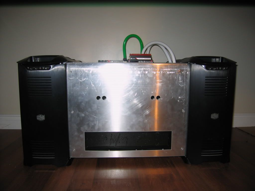
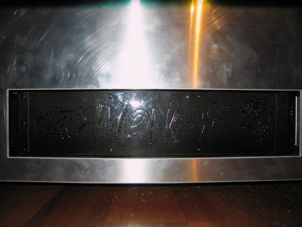
well im going to start off by saying this is a post for the build log of my new custome case/system which im calling FERMI 2
It was supposed to be called FERMI 3 but i sold off my FTW 480 today (money constaints).
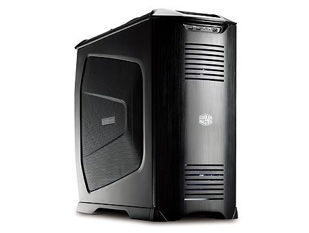
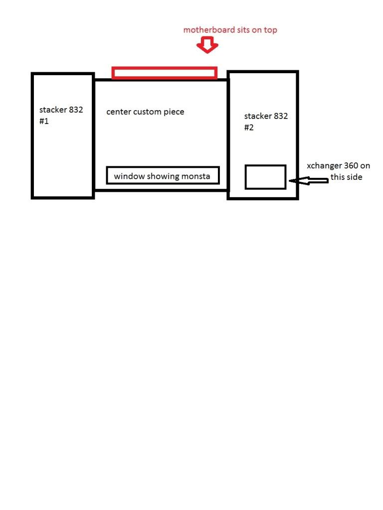
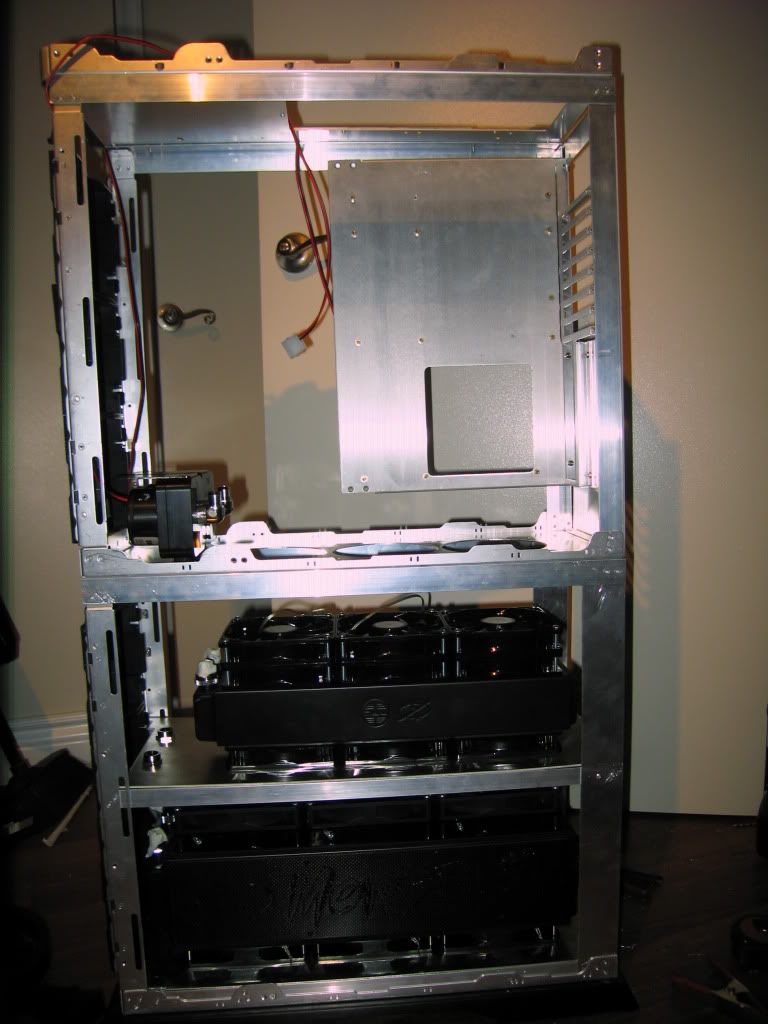
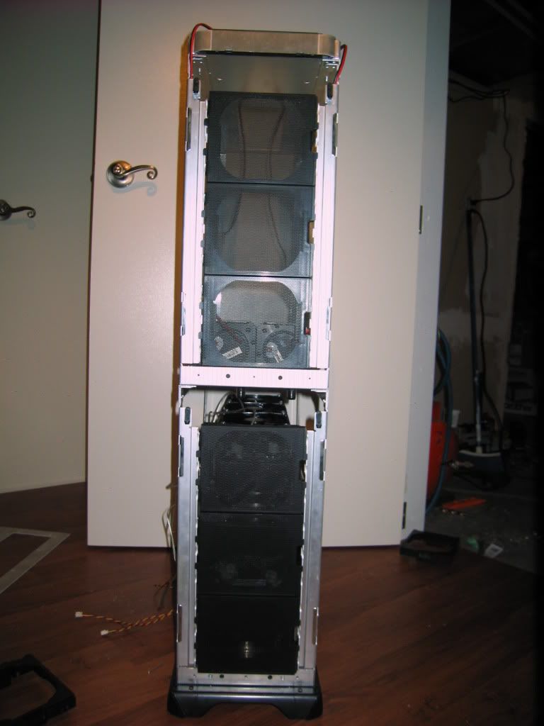
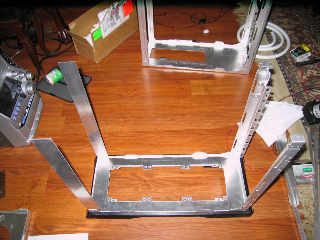
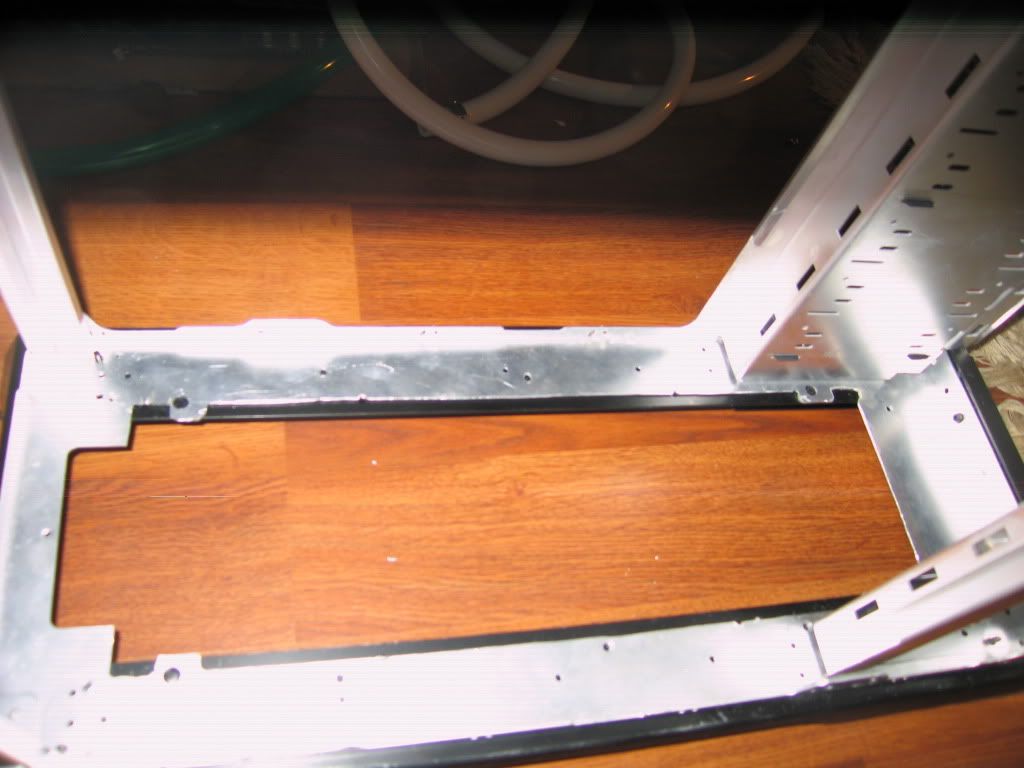
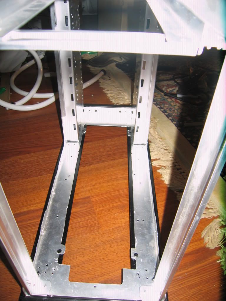
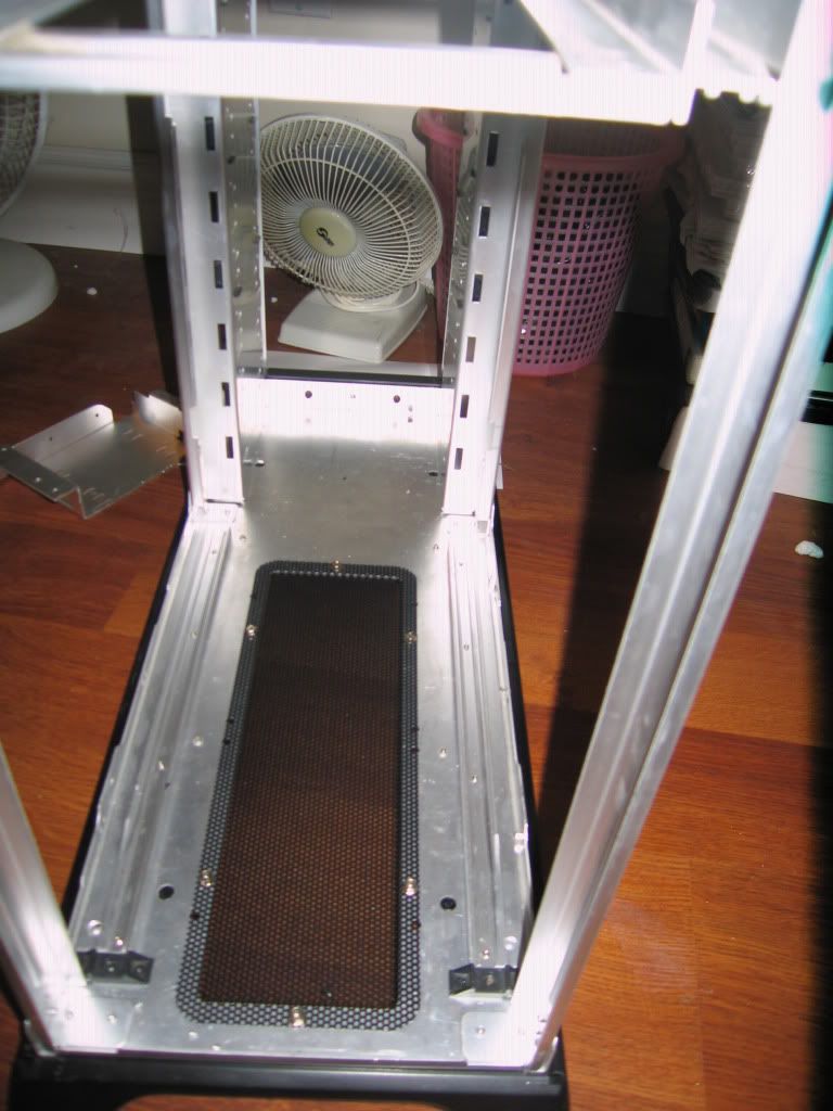
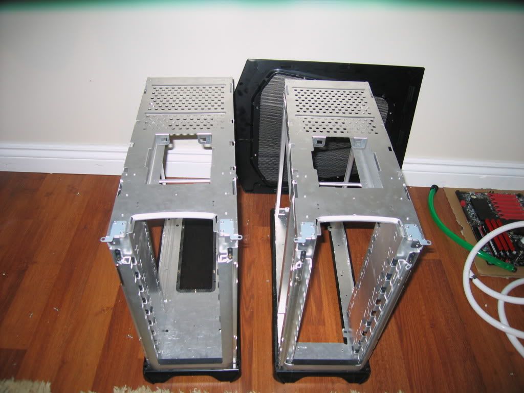
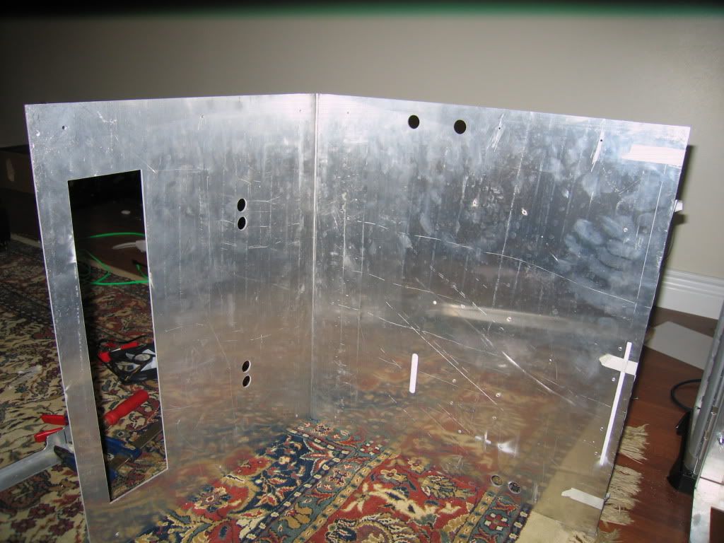
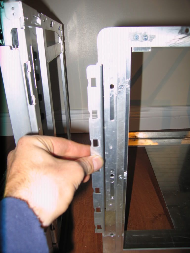
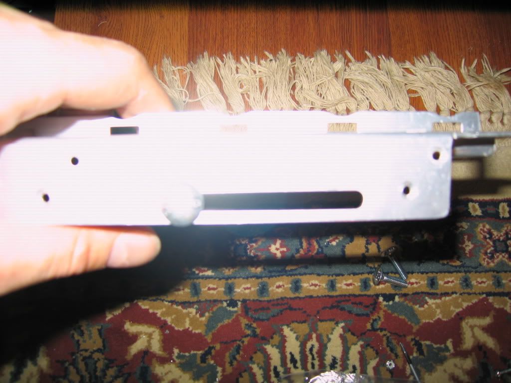
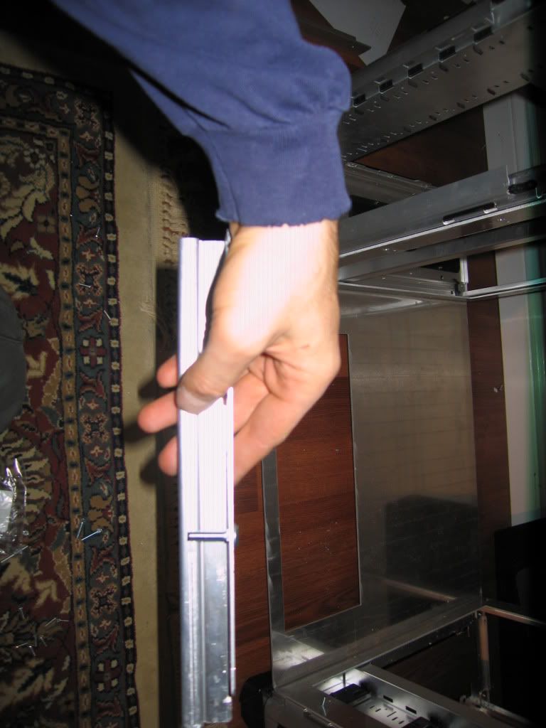
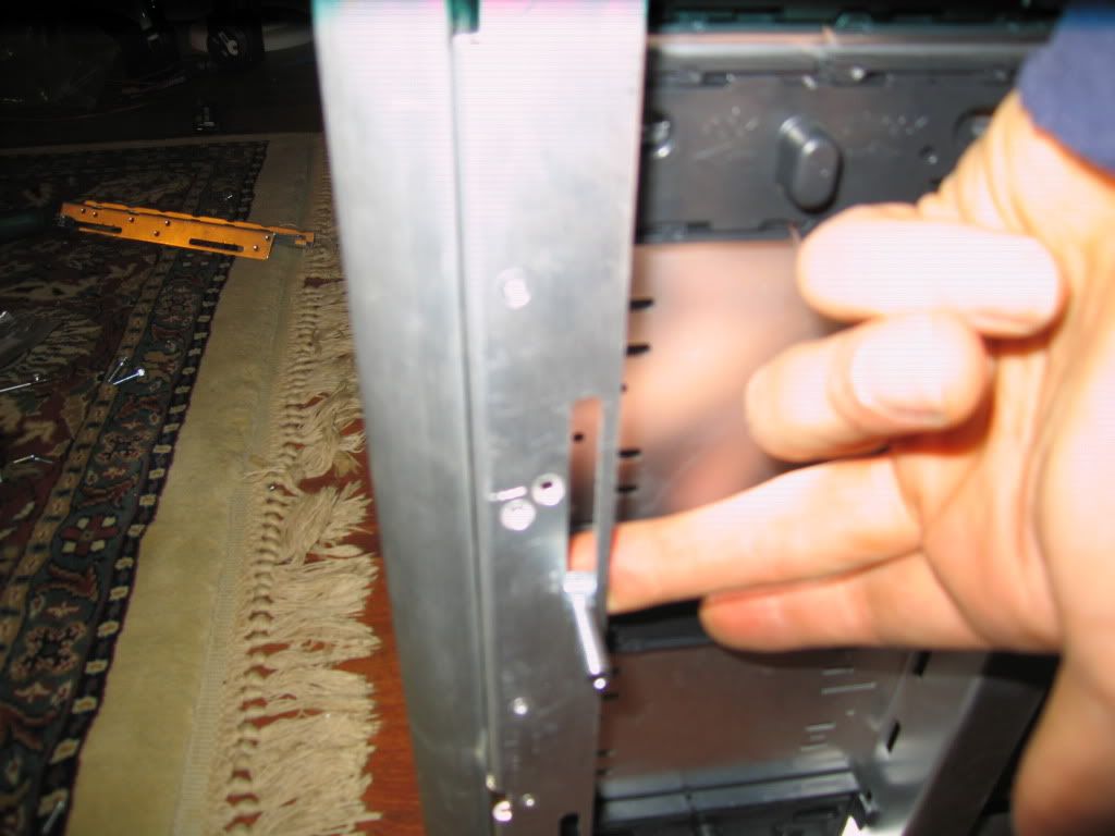
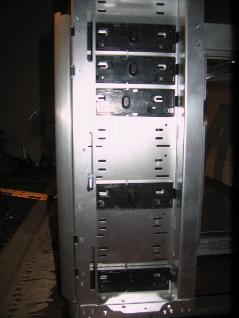
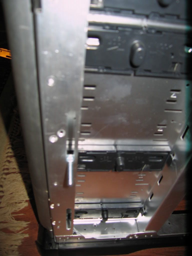
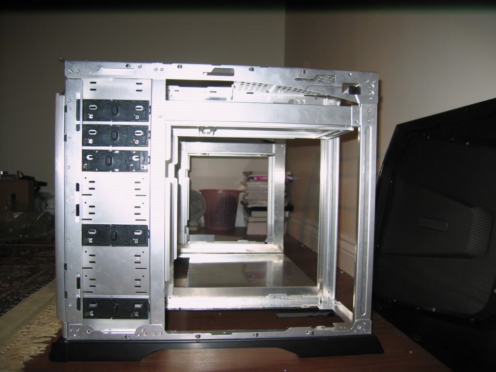
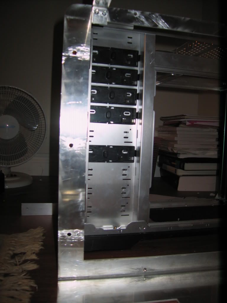
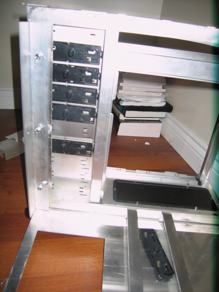
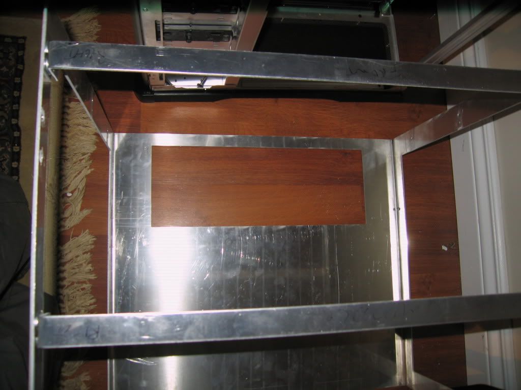
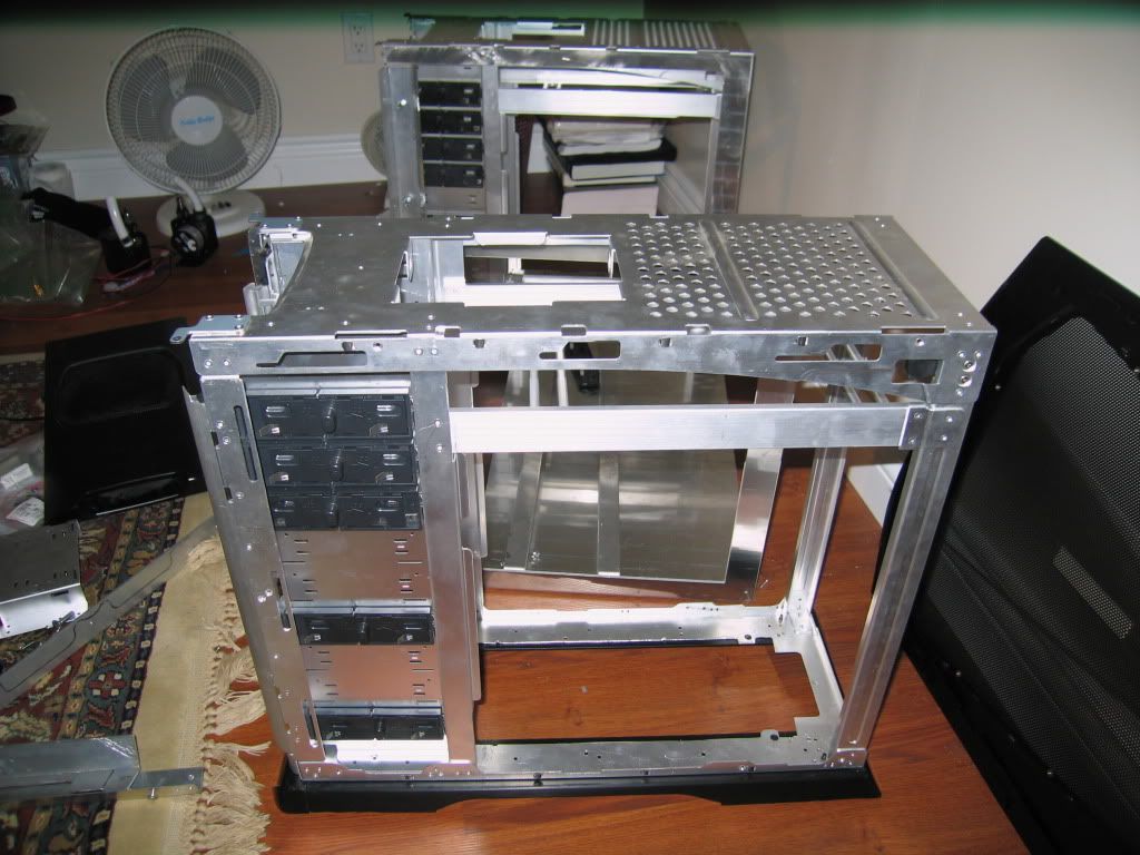
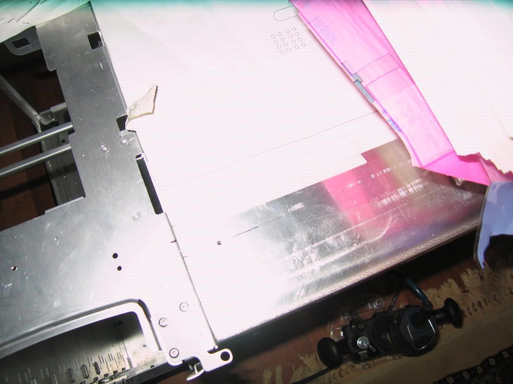
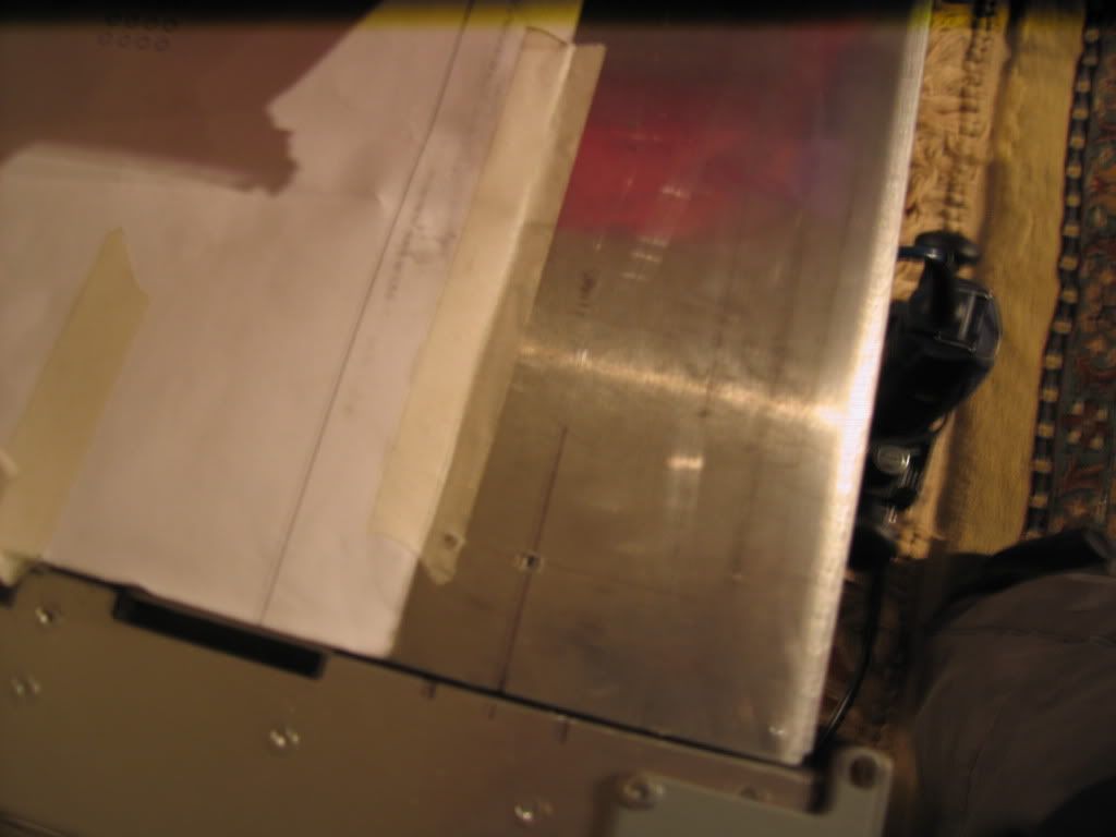
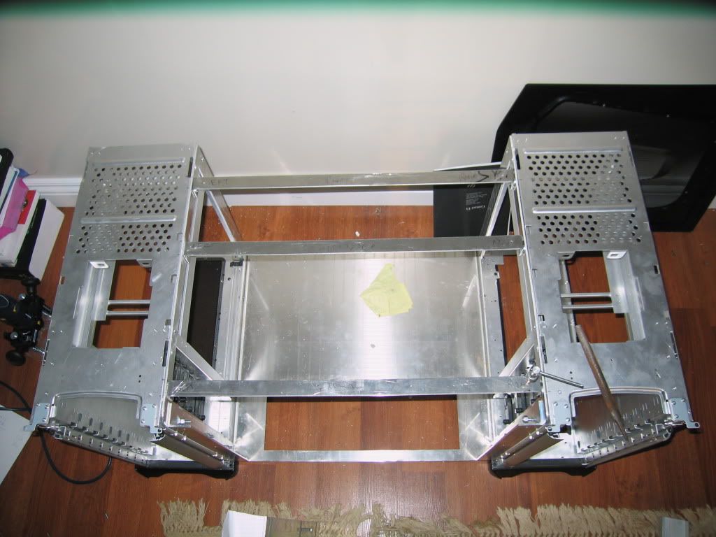
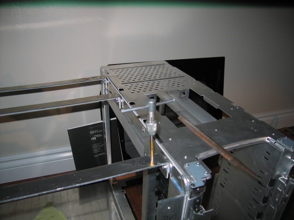
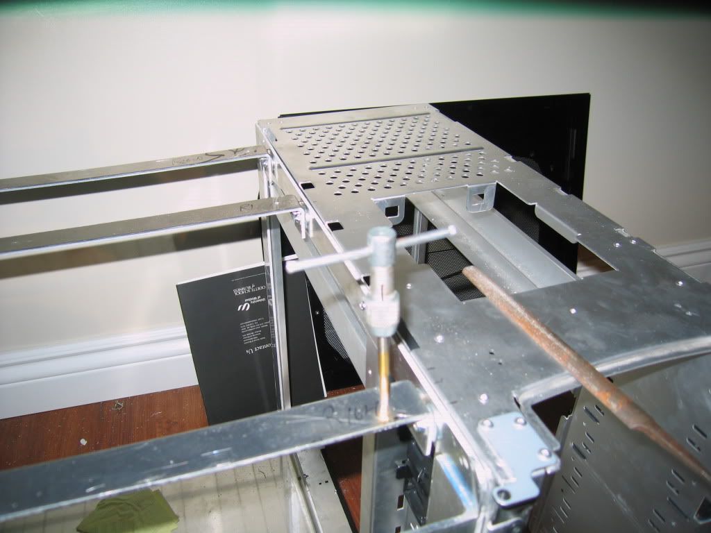
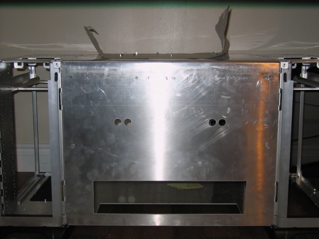
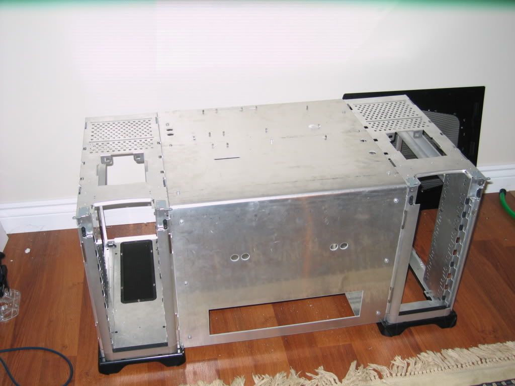
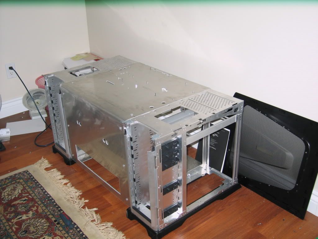
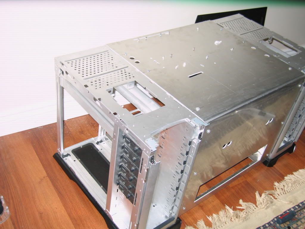
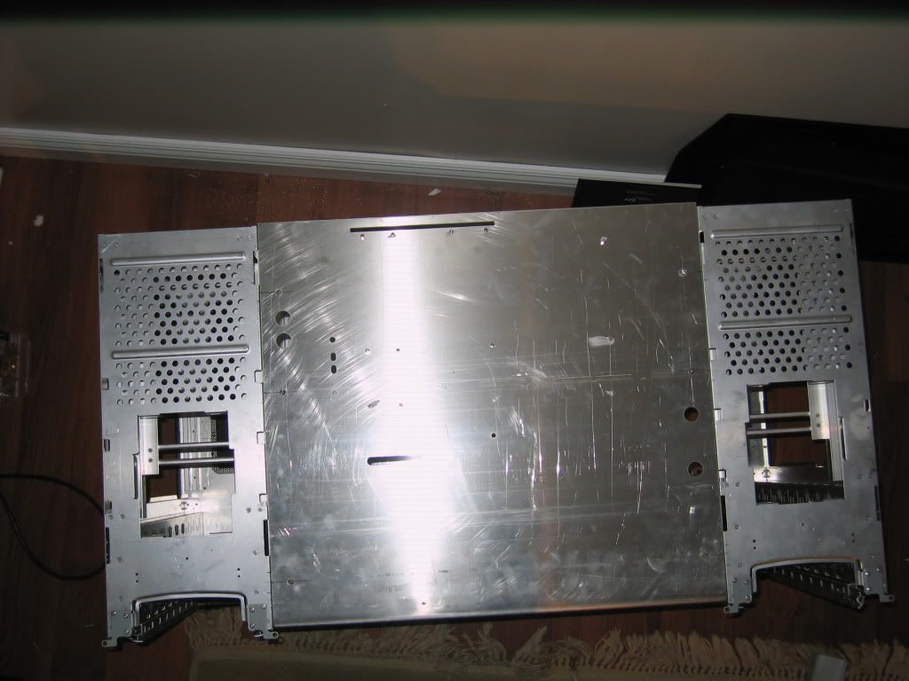
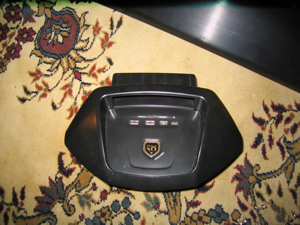
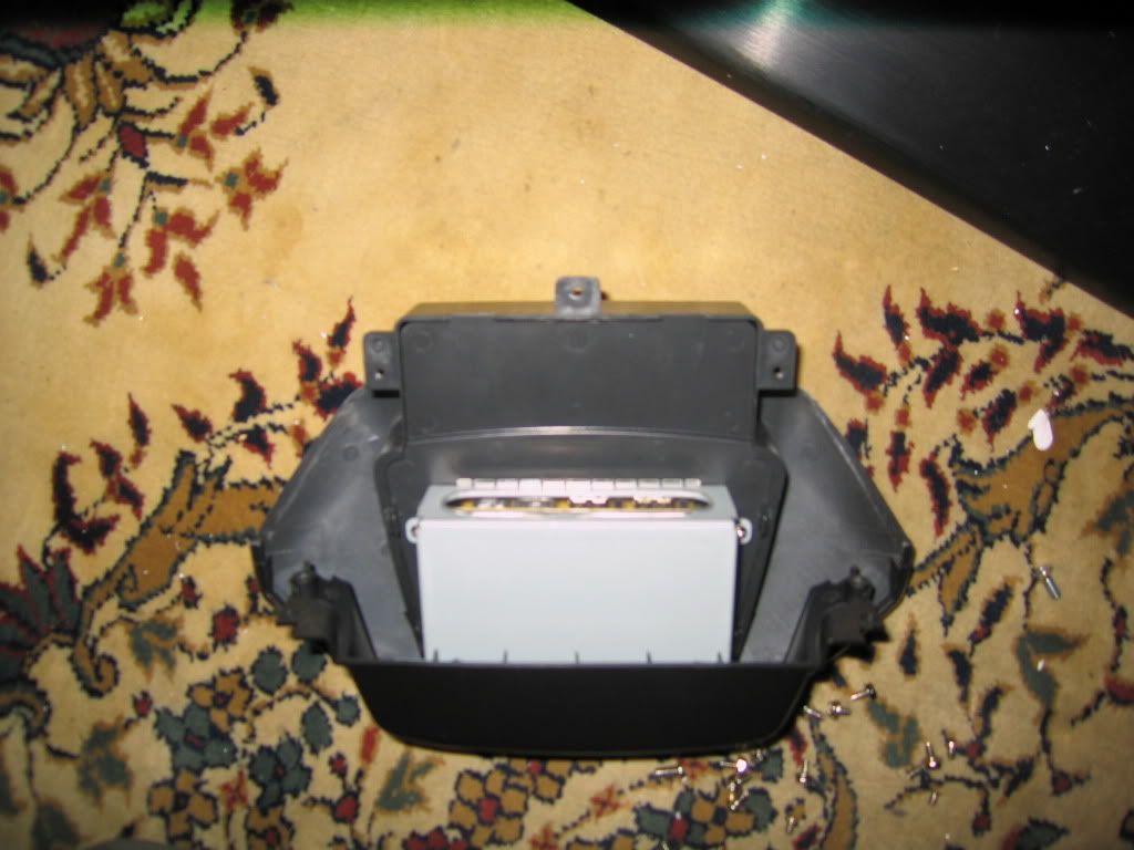
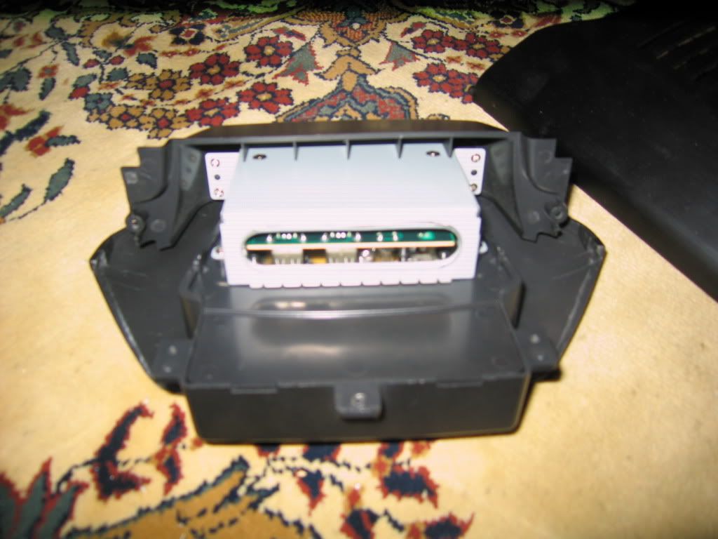
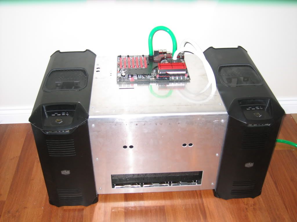
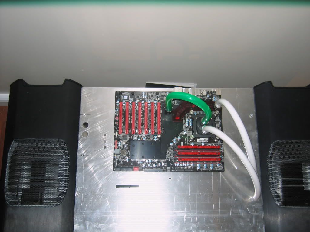
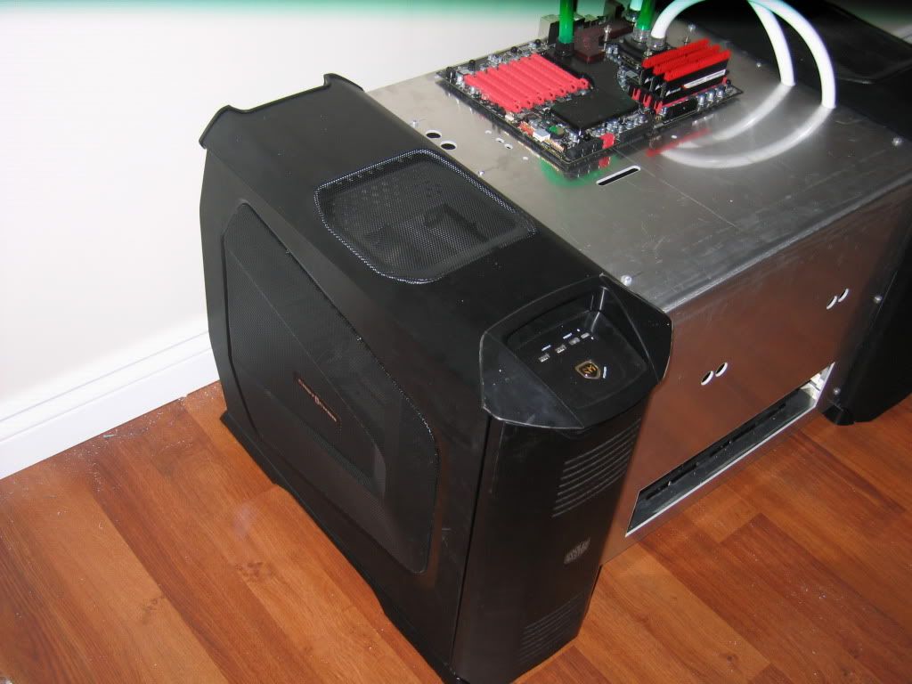
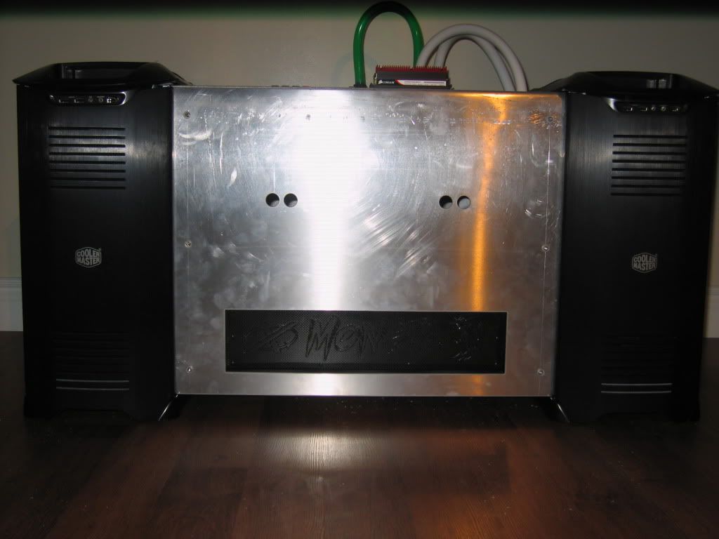
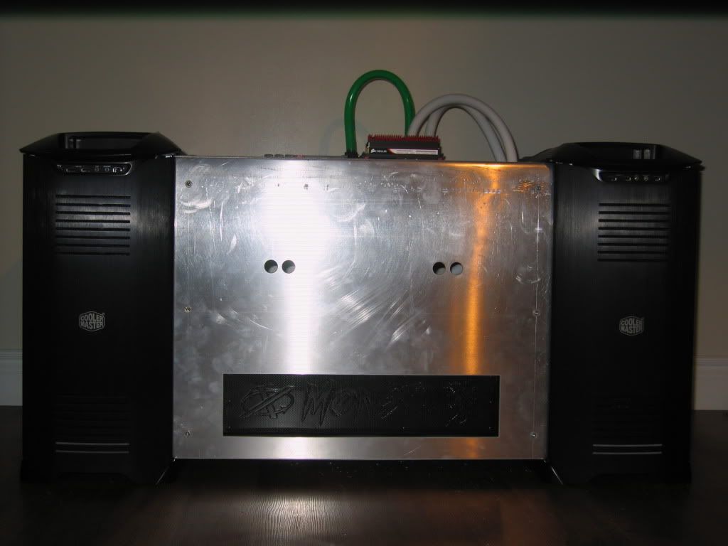
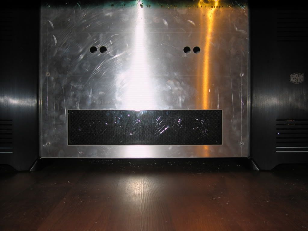
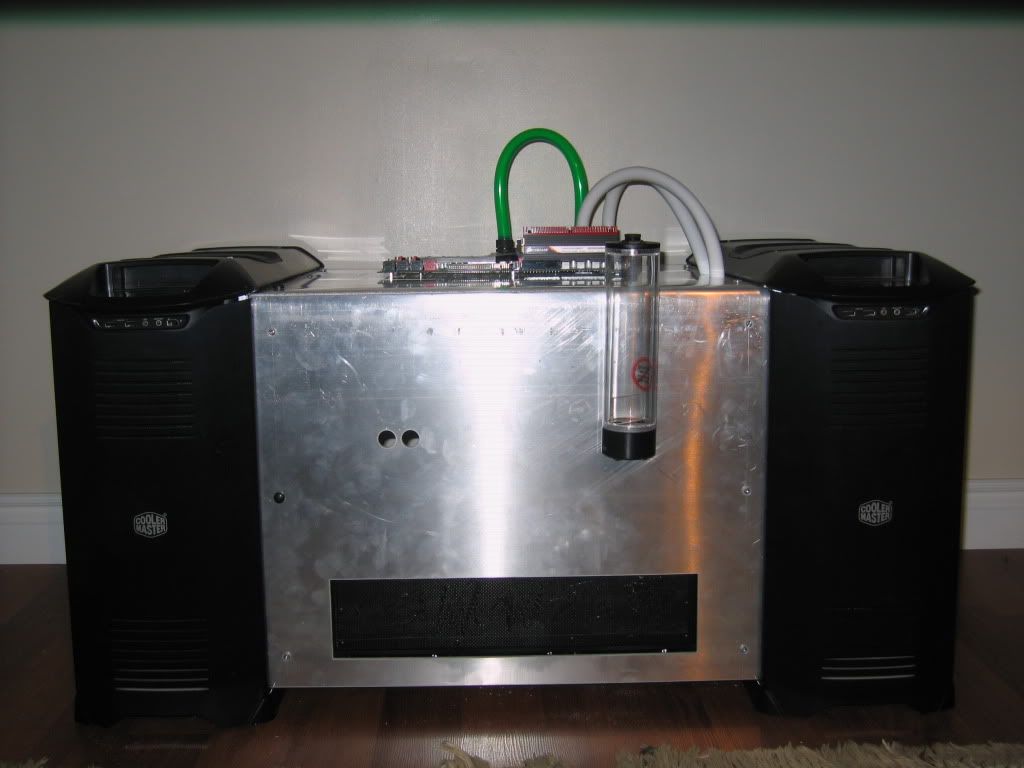
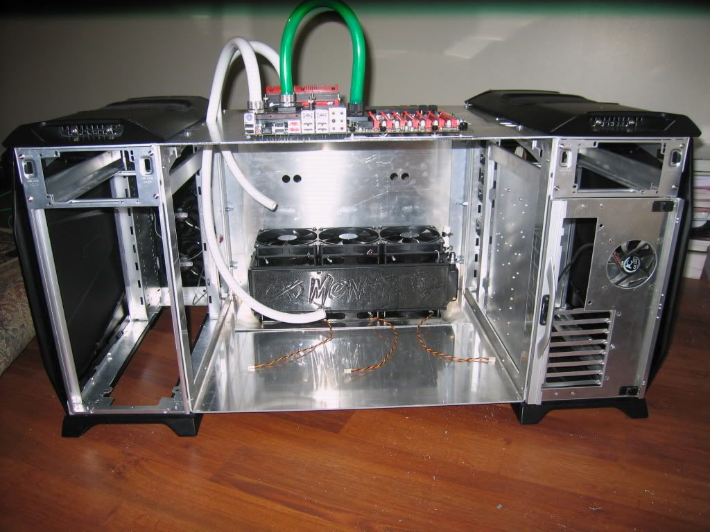
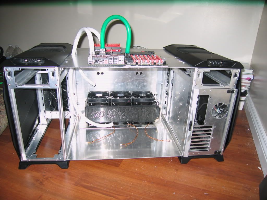
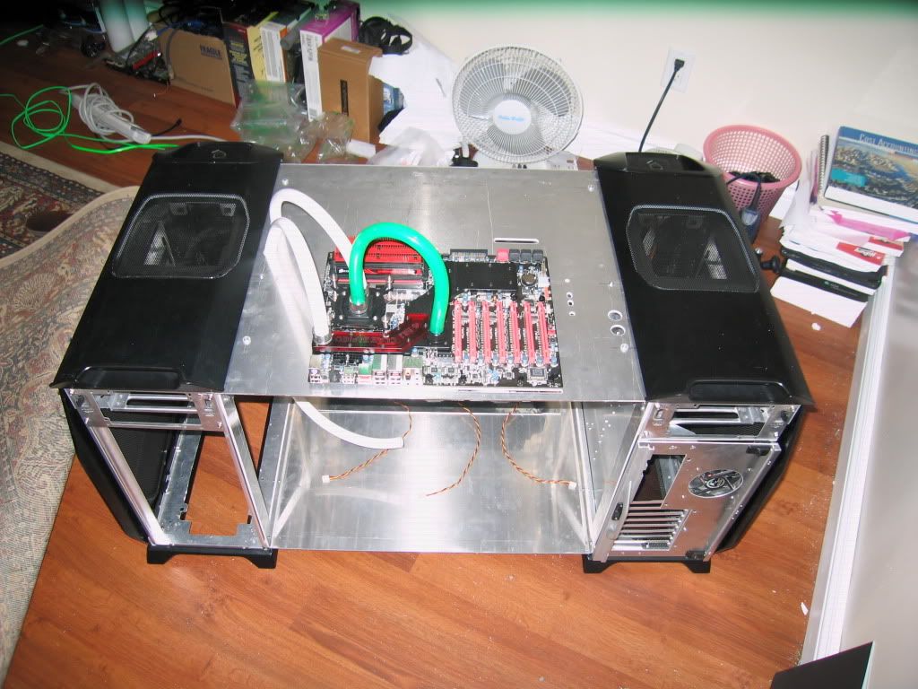
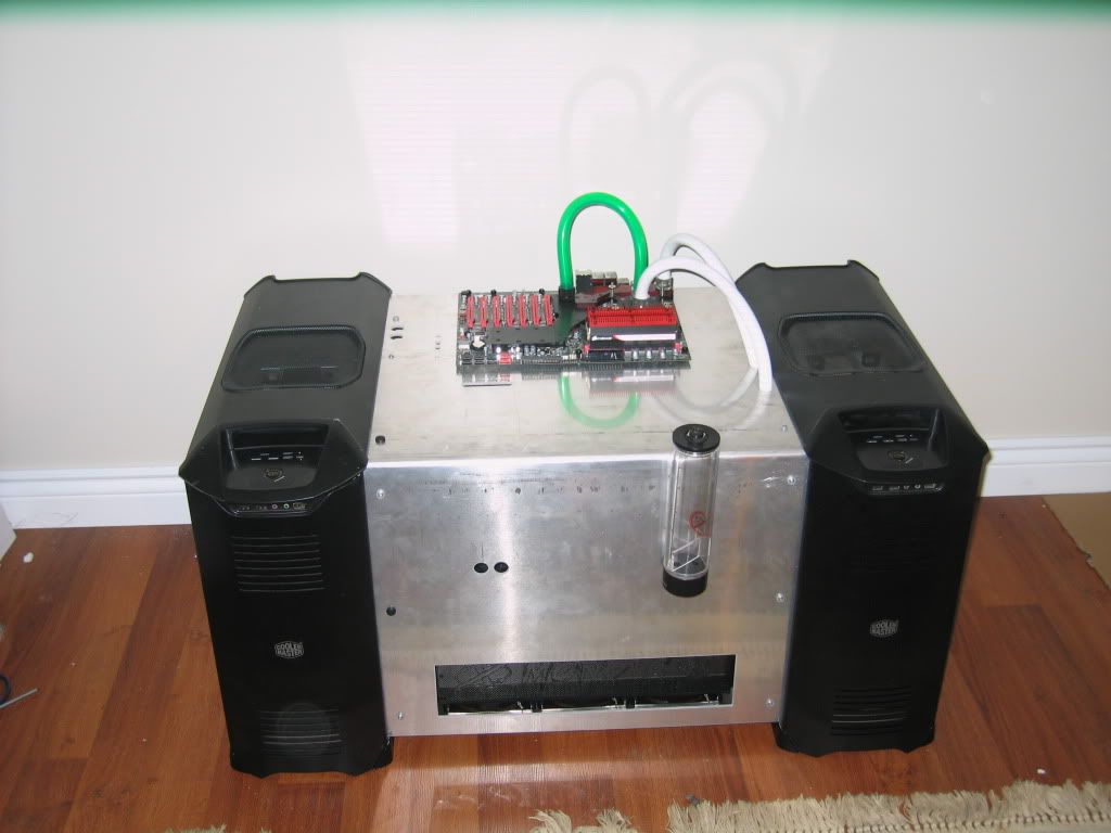
the case is made out of 2 coolermaster stacker 832 cases which i think you guys will like
I have went through many revisions of this case and now have finally found one i like and that works well which is REV 4 right now
WHY I CHOSE TO CALL MY SYSTEM/CASE FERMI 2
Fermi is the name of a Nuclear power plant. I live in Windsor, Ontario Canada which is located across from Detroit, Michigan. Now there is an actually power plant near windsor and detroit (10-20 miles away) called FERMI 2. Its a nuclear power plant
since each gtx 480 is from the Fermi Family, I decided to call it FERMI 2. Ill be using 2 corsair 850w power supplies (2 generators), so Ill be putting 1700W or 1.7kW Capacity on the case maybe with red leds behind an engraved acrylic panel
Now if i decide to buy a 3rd GTX 480 (just sold my third one ... ) than ill be naming it FERMI 3.
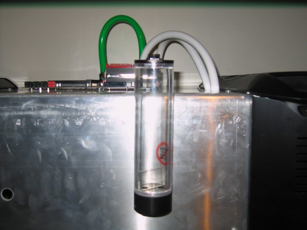
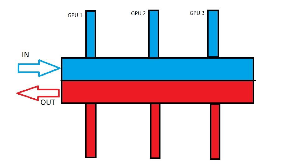
Now there are 2 Fermi Cards (reactors), 2 cooling towers (2 radiators), 2 dump tanks (used for emergencies) (2 reservoirs), the the whole theme goes well with the case.
Let me know what you think.....
so
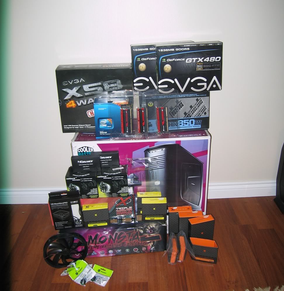
the system consists of the following:
Hardware:
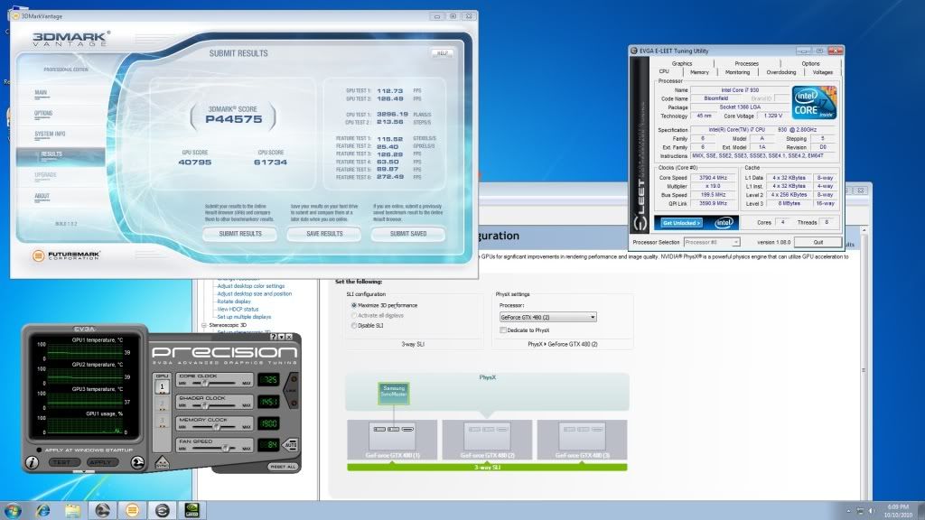
Core i7 930
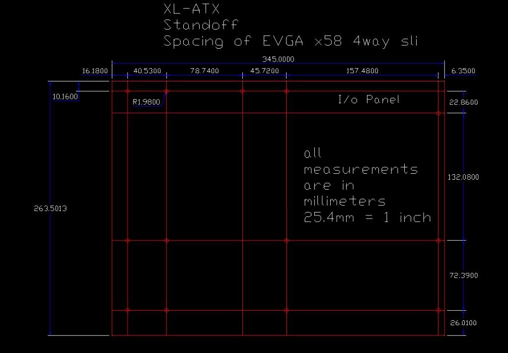
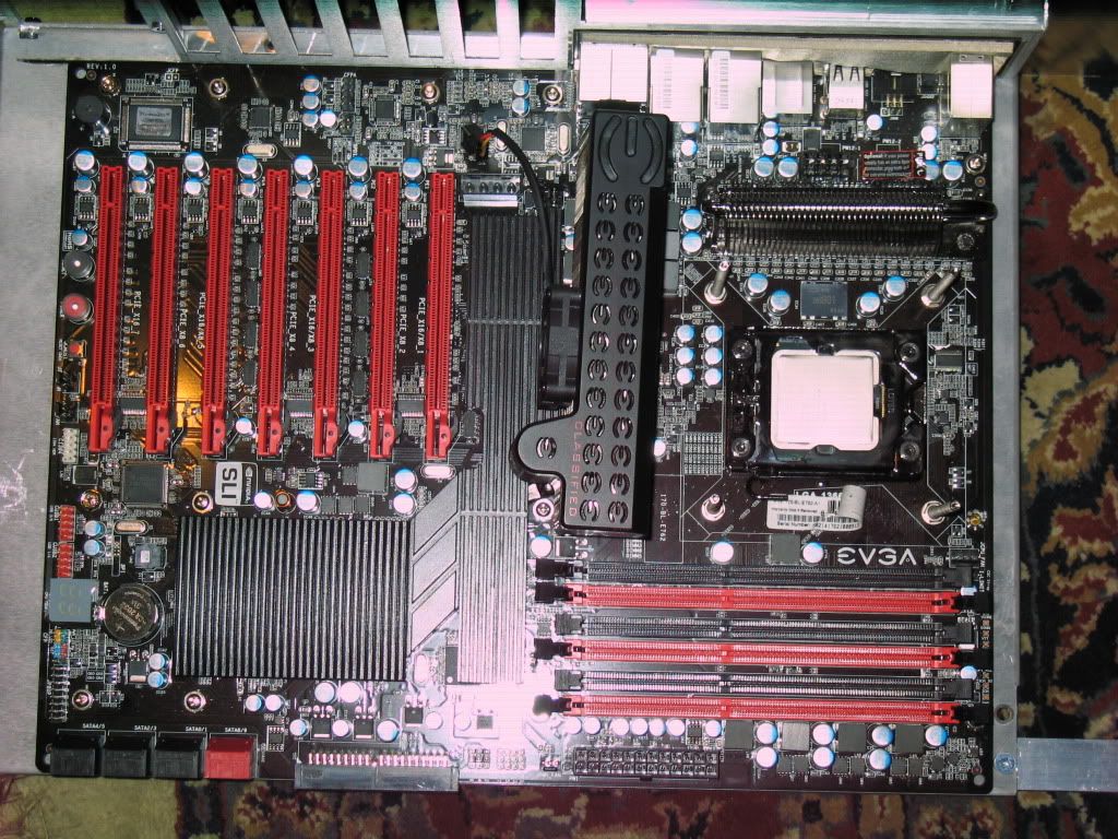
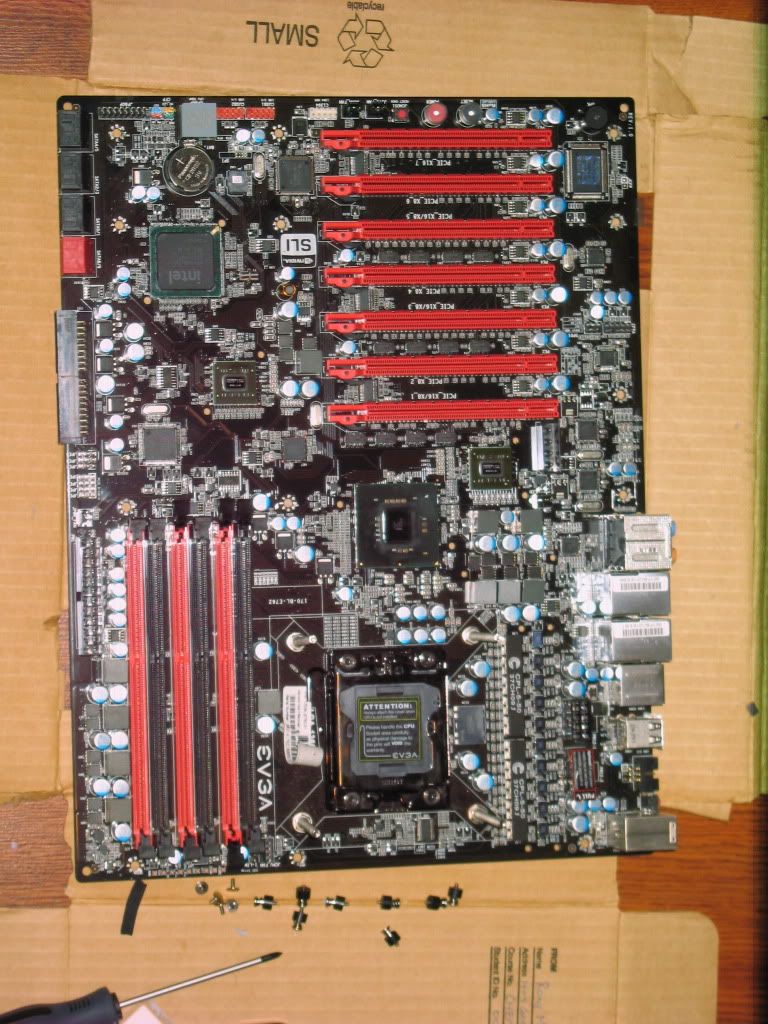
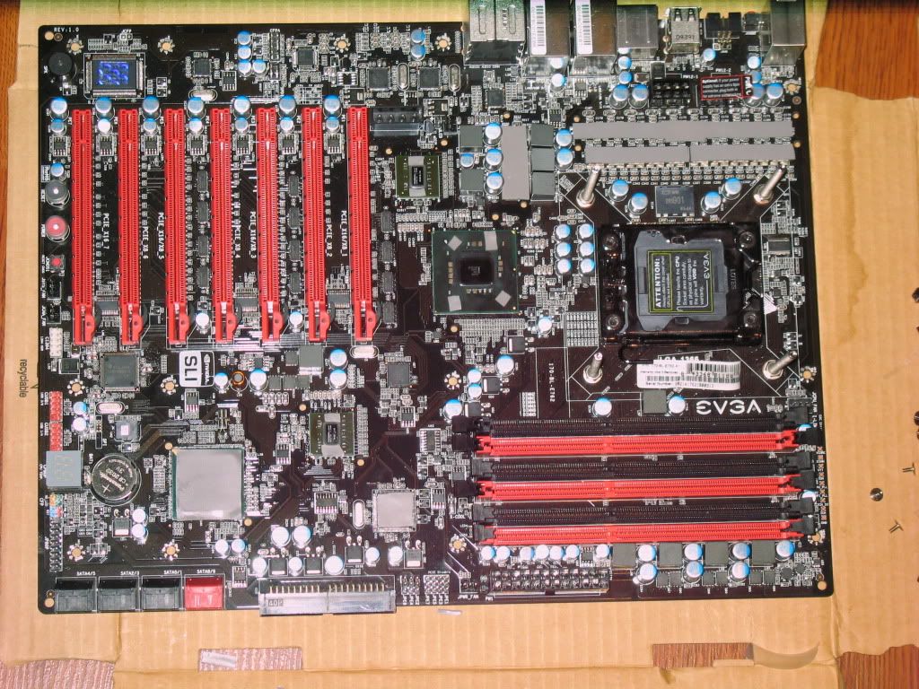
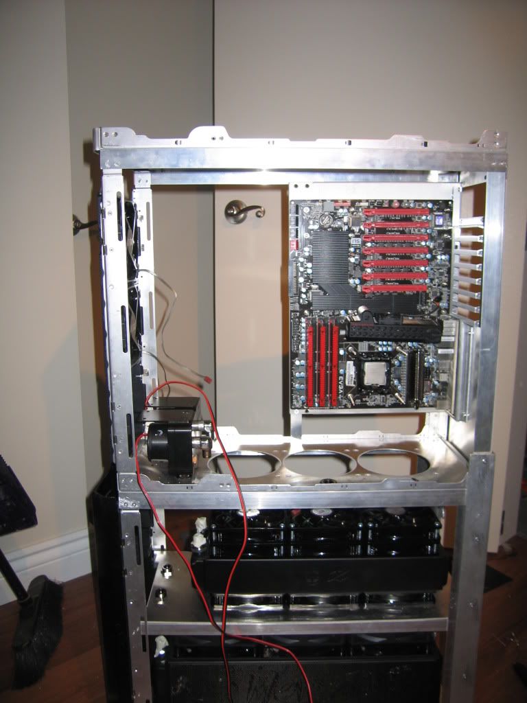
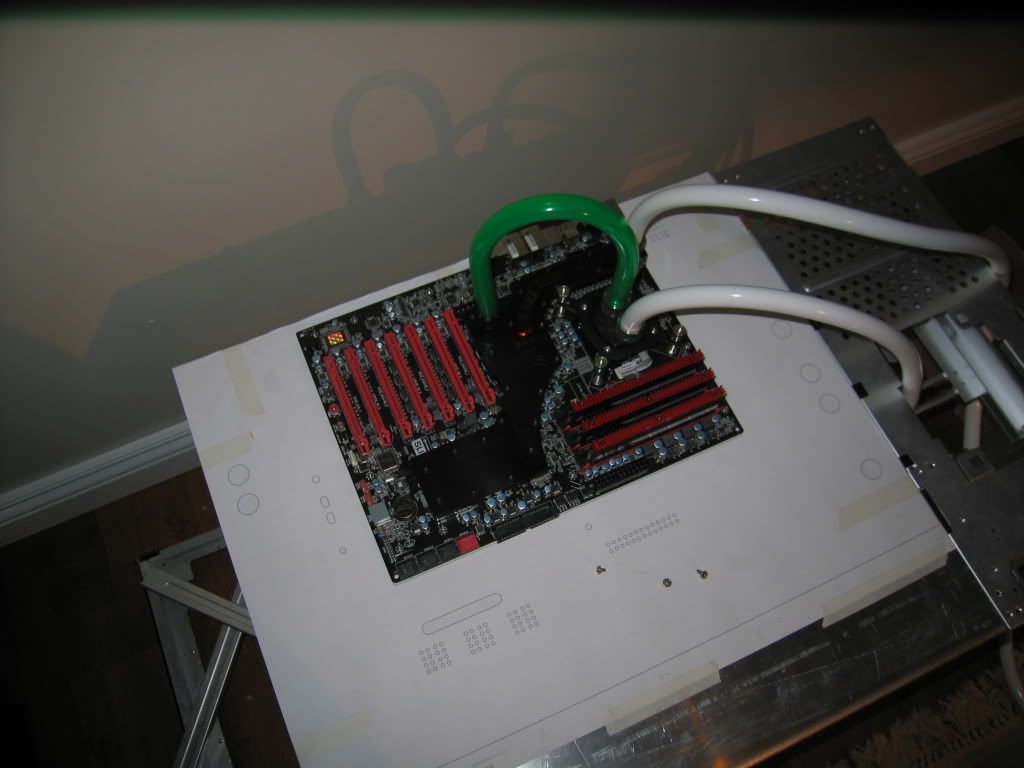
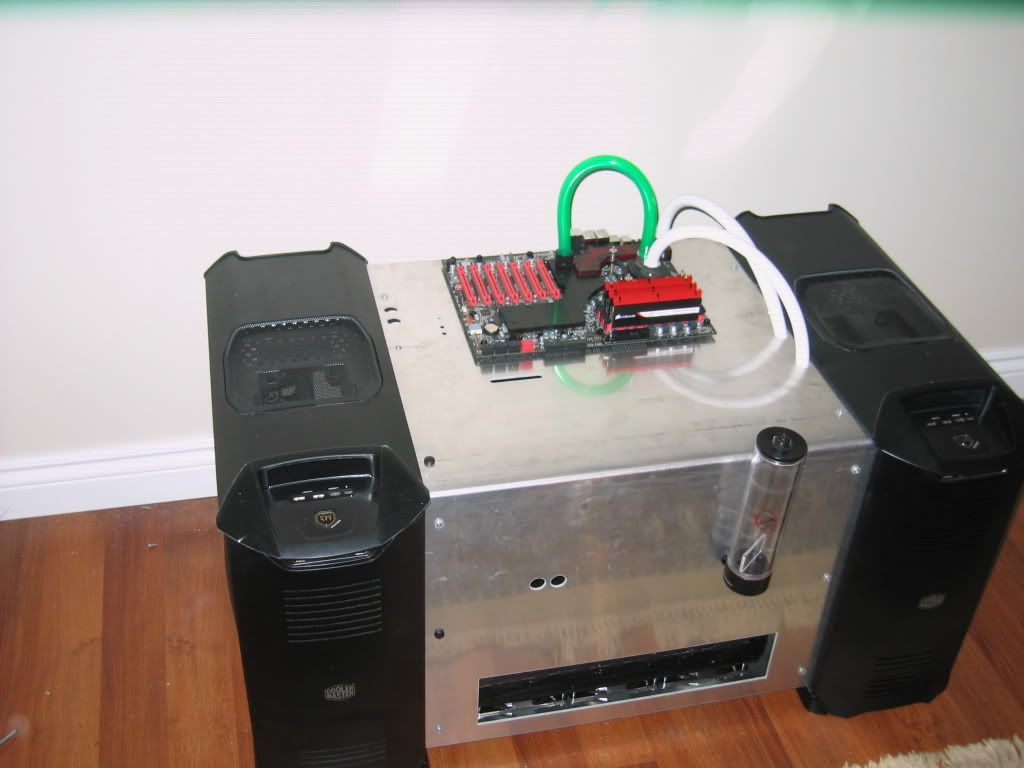
EVGA X58 4 way sli Mobo
Corsair Dominator GT 2000c7
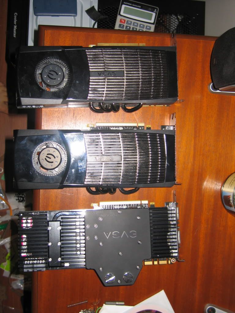
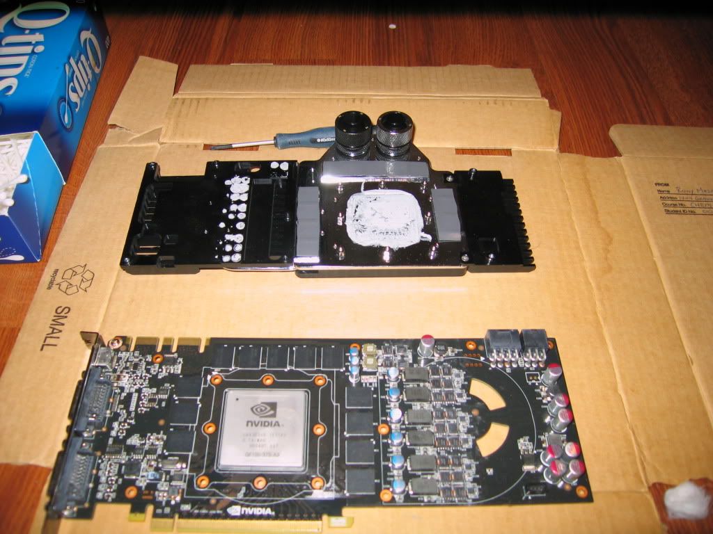
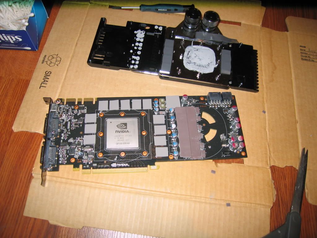
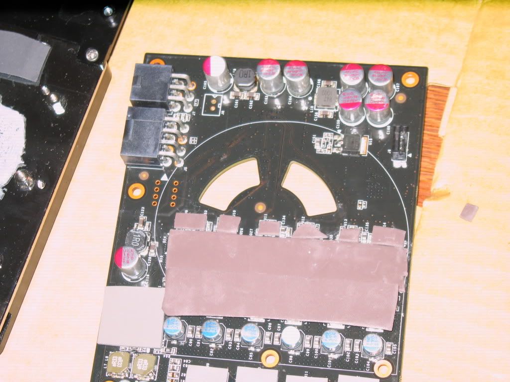
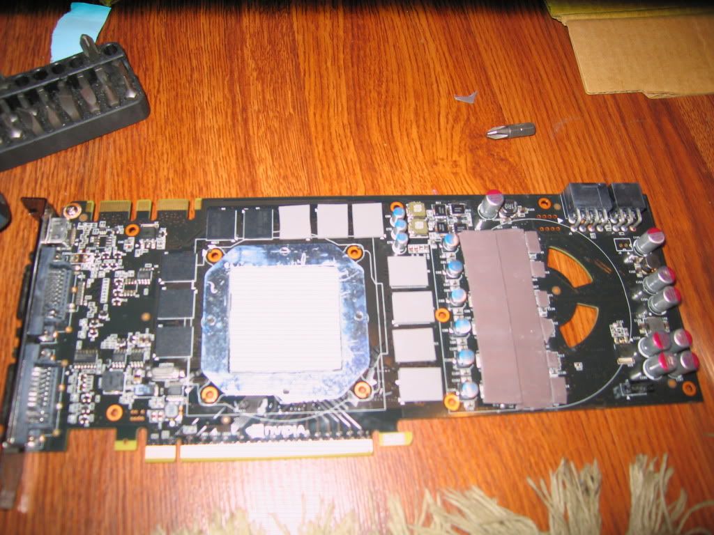
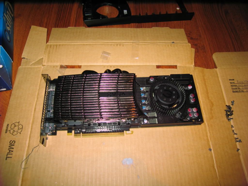
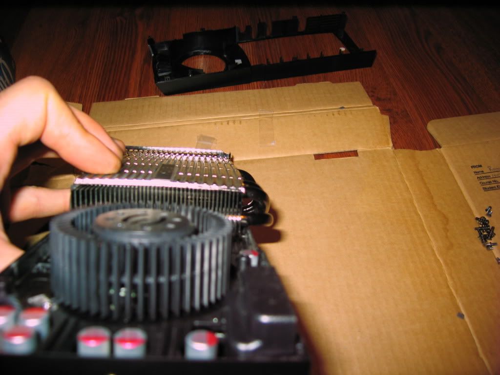
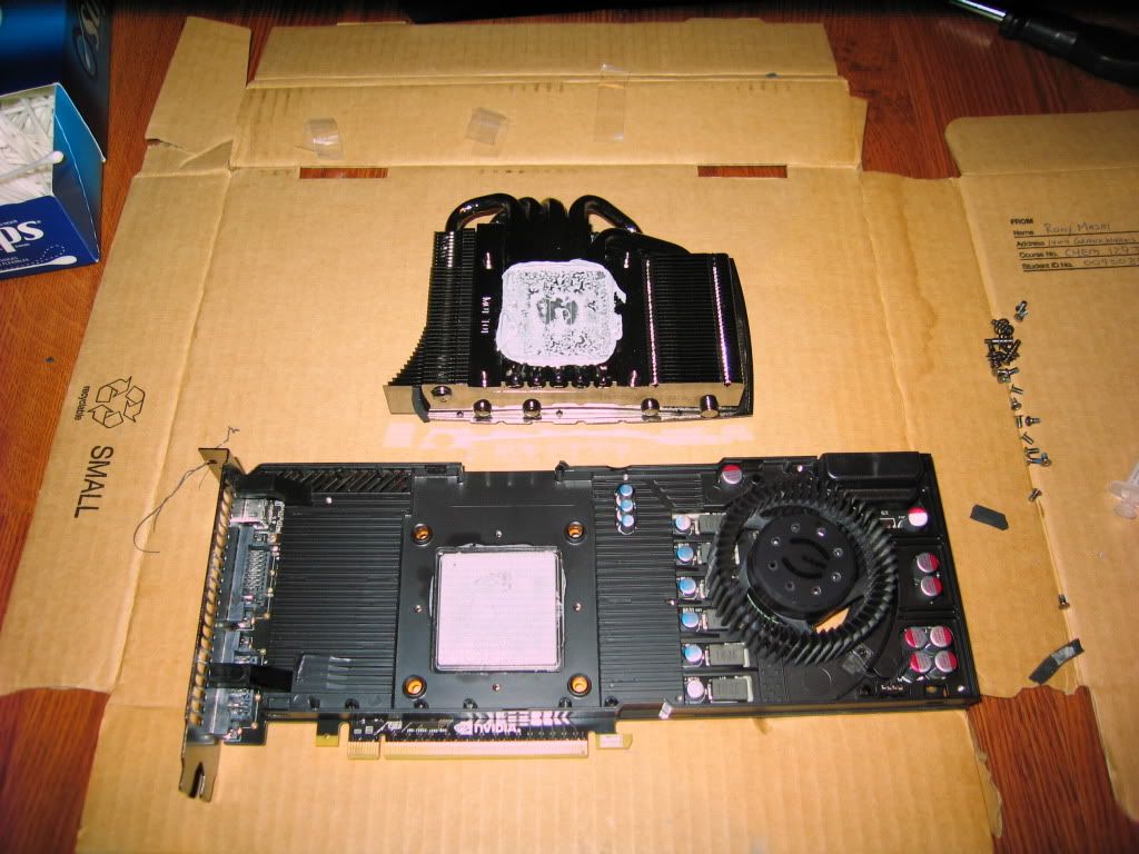
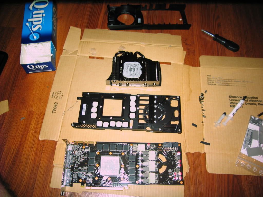
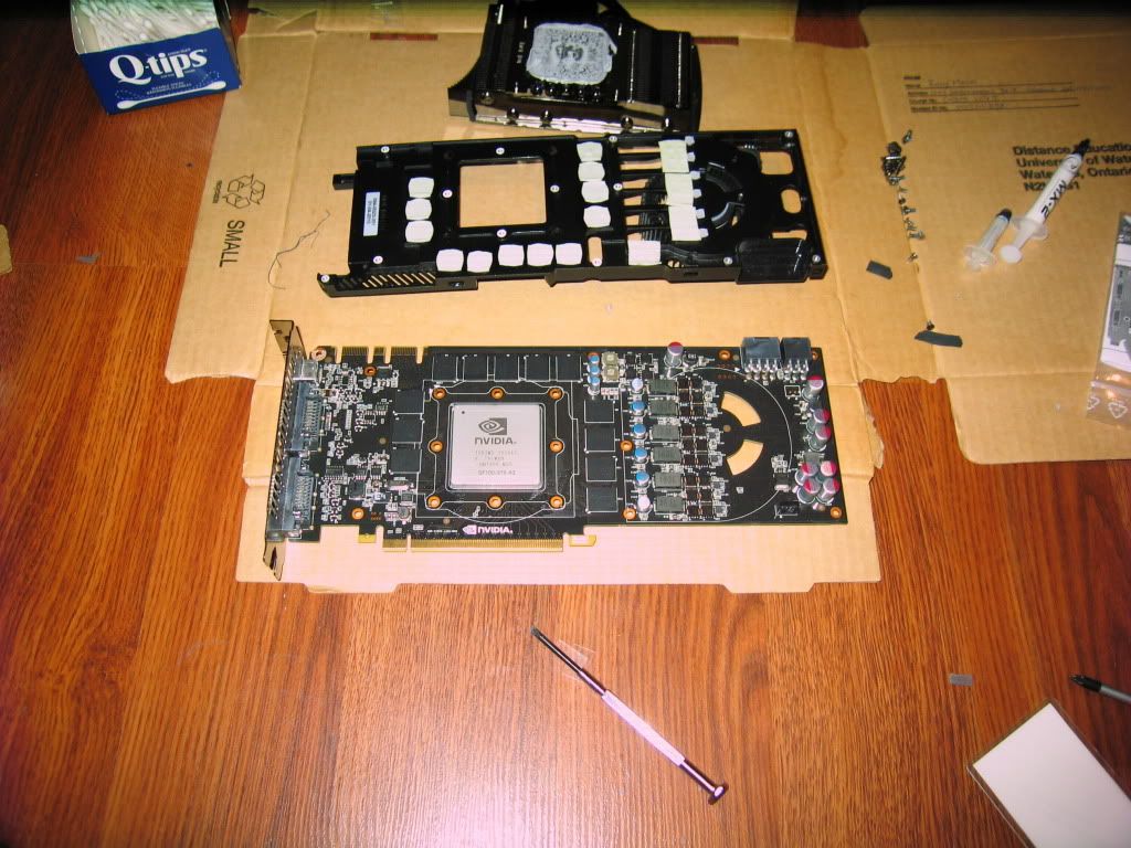
2 - EVGA GTX 480's Super Clocked editions
1 - Corsair HX850w power supply
1 - Corsair AX850w power supply (will get it in 2 weeks as i sold one of my two hx850's that was with my HD5970 build)
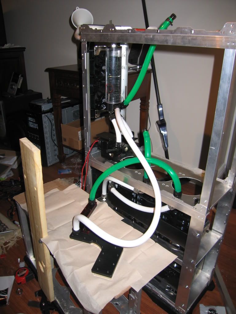
Watercooling:
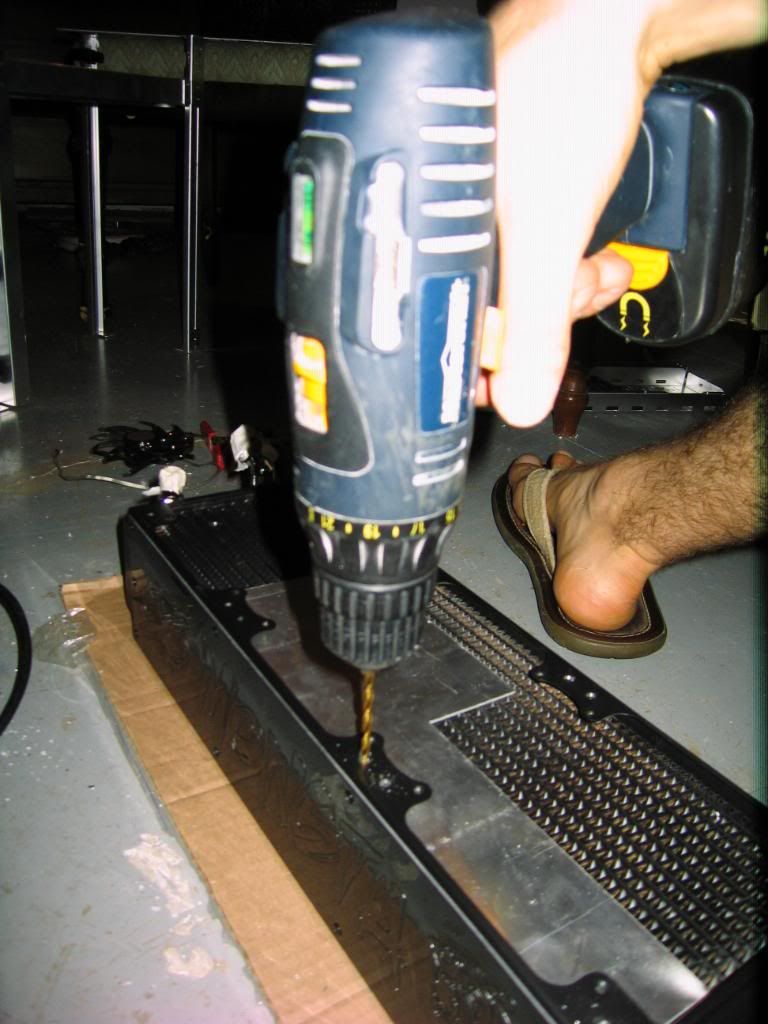
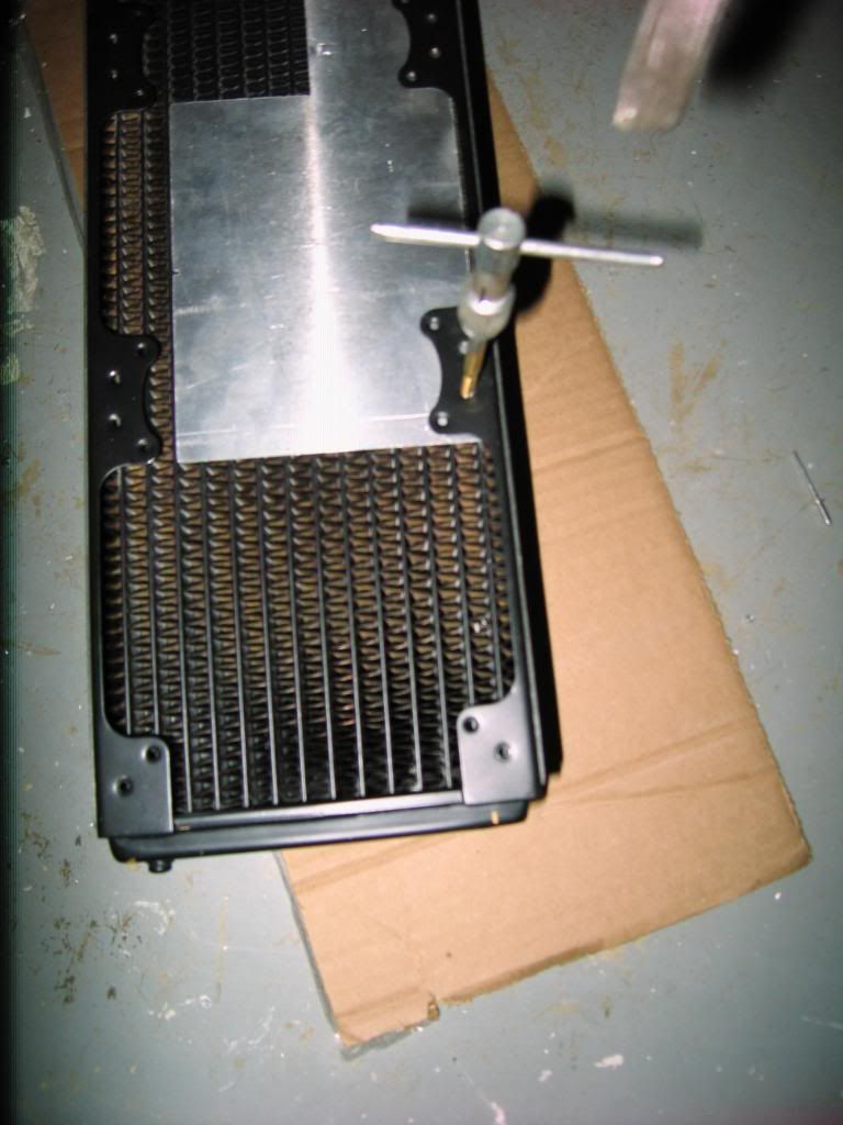
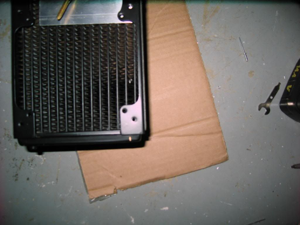
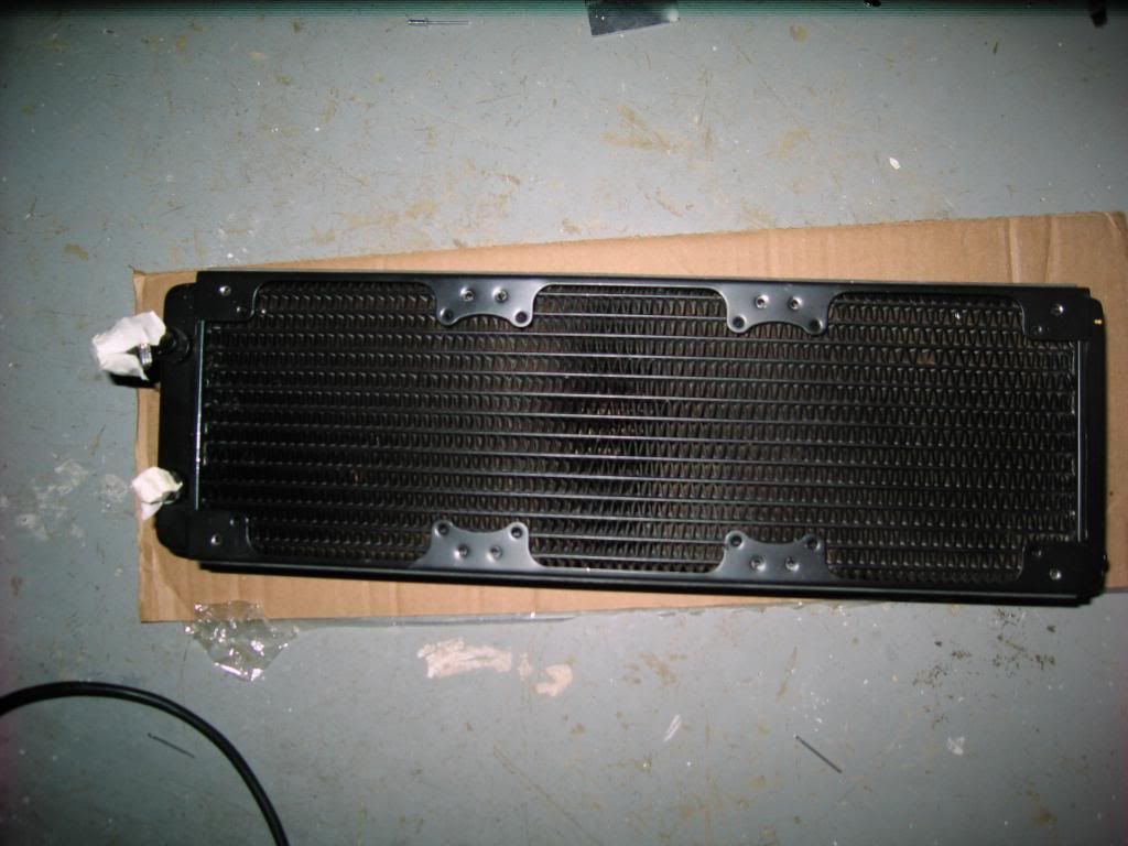
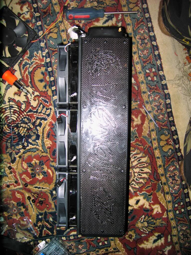
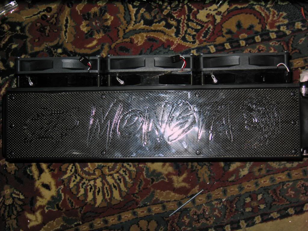
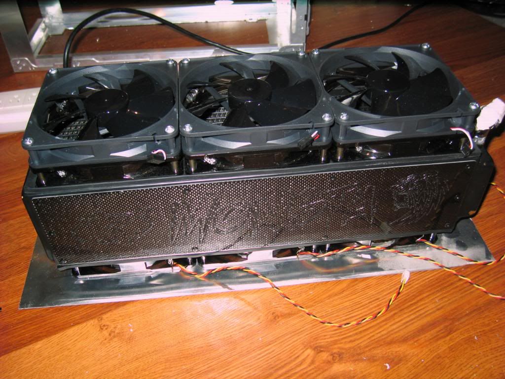
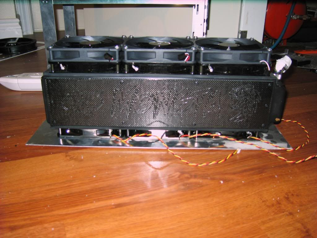
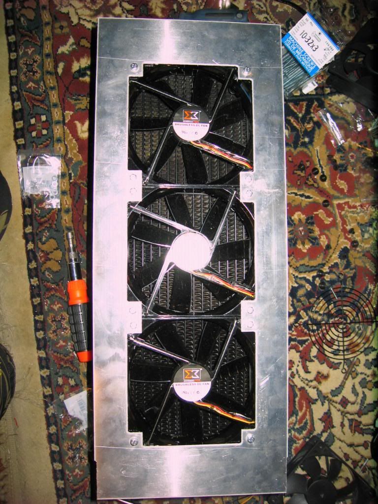
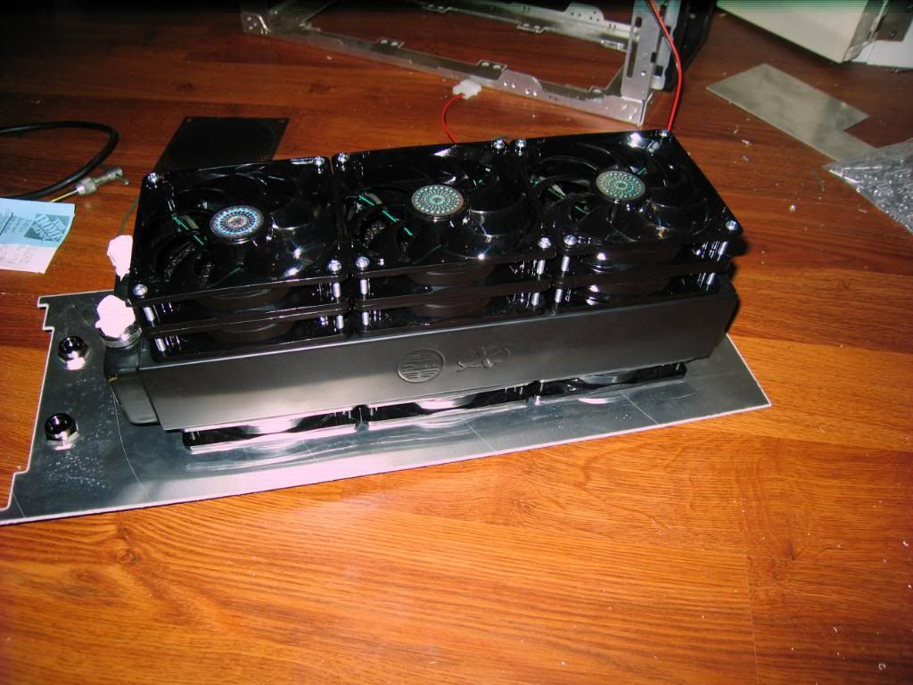
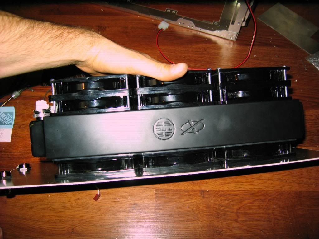
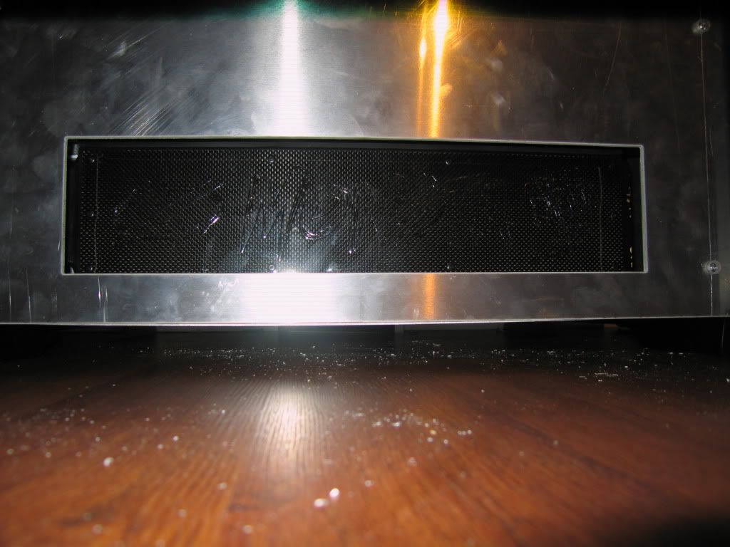
Feser 420 Monsta Radiator
Feser 360 Xchanger Radiator
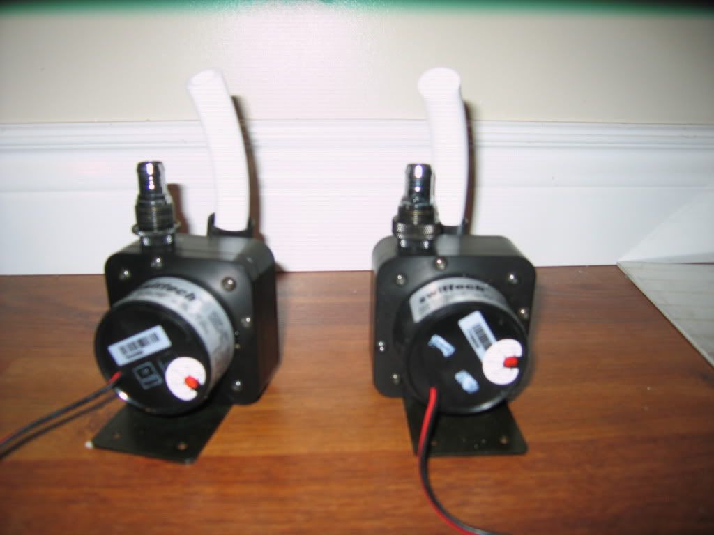
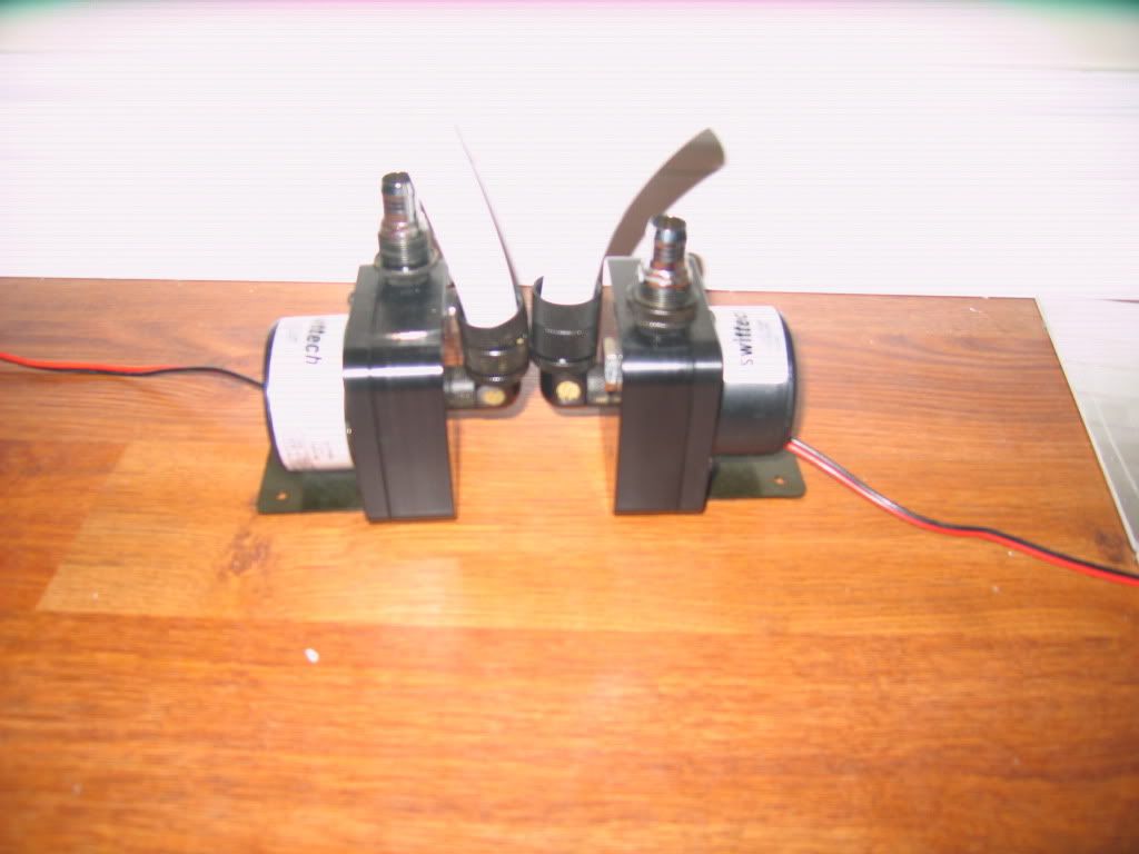
2 - Swiftech MCP-655 Pumps
2 - EK MCP-655 X-TOP Ver. 2
2 - Koolance 120mm Reservoirs
EK Supreme HF cpu block (black + nickel)
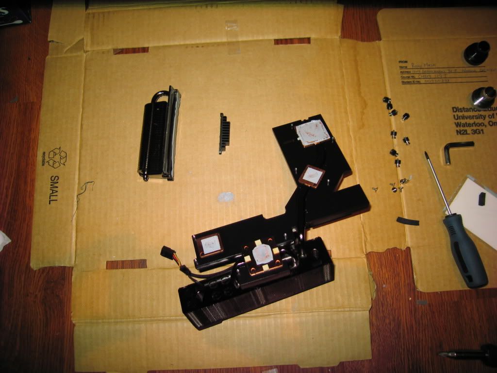
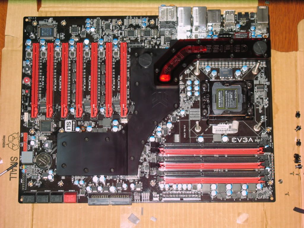
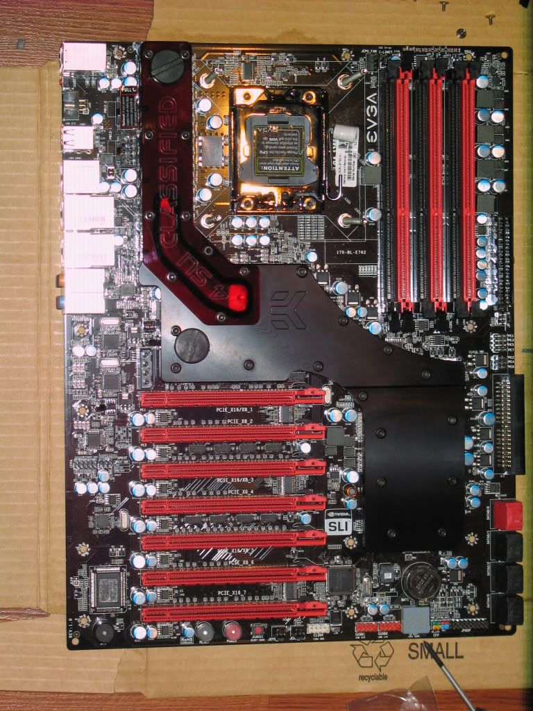
EK Classified 4 way Full Motherboard Block
MIPS computer Corsair 6 Ram Block
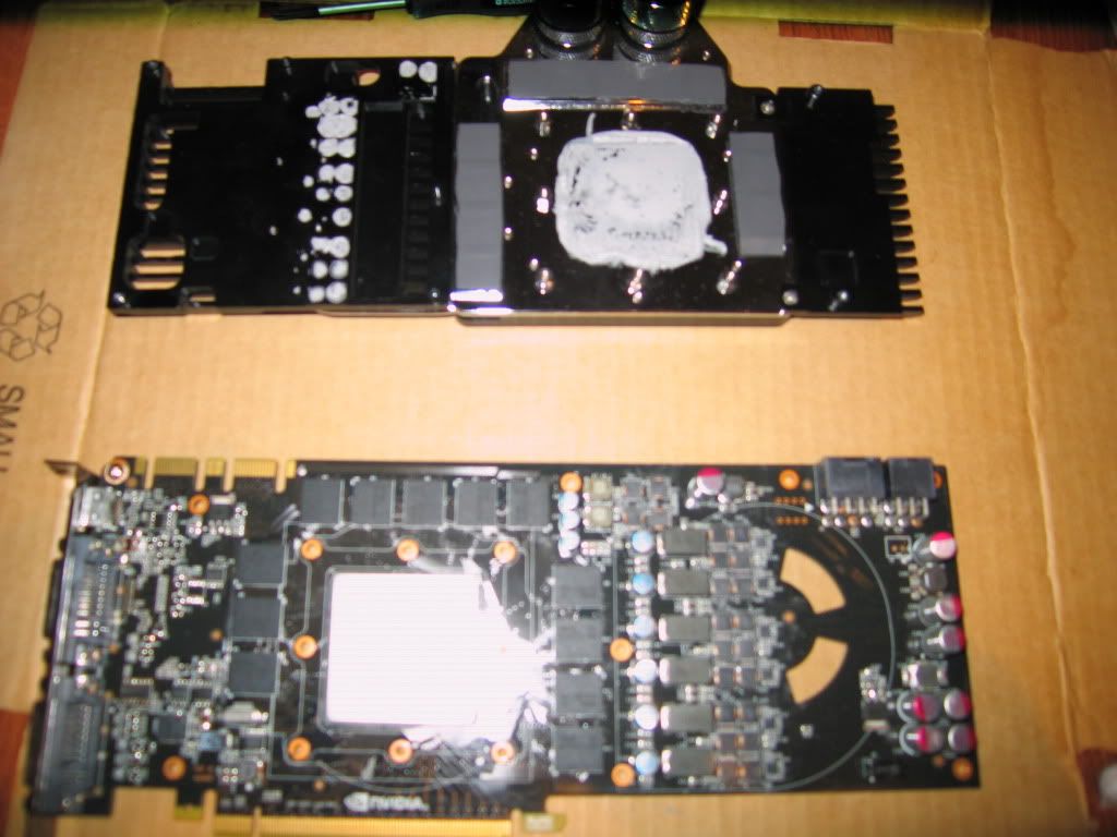
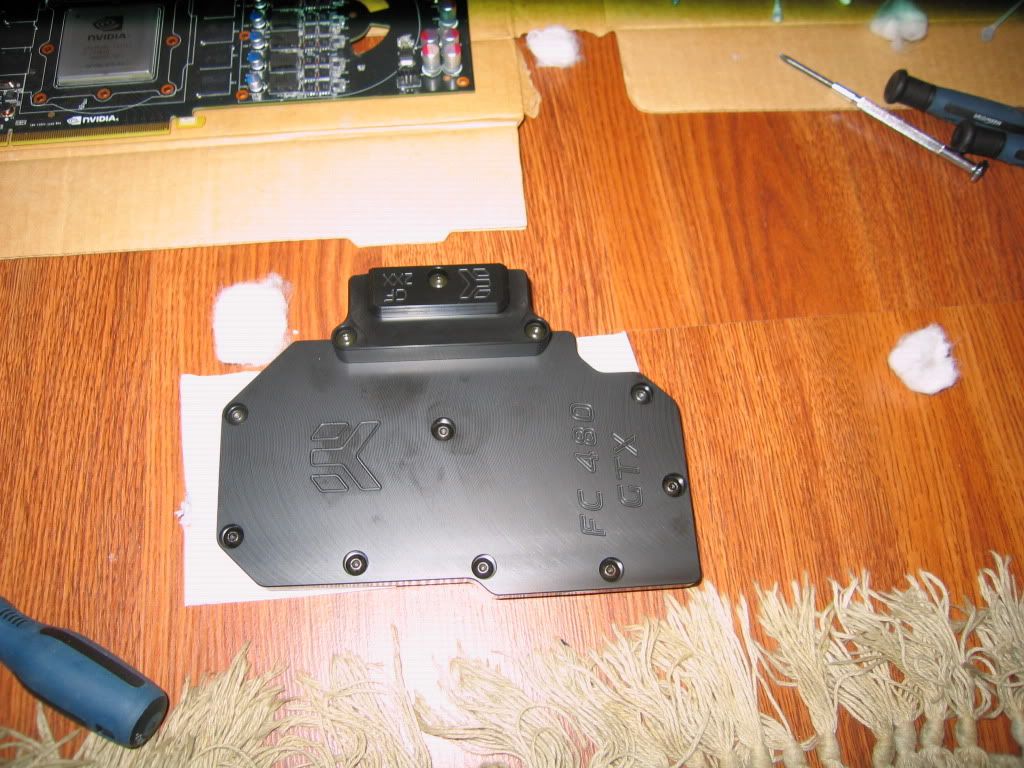
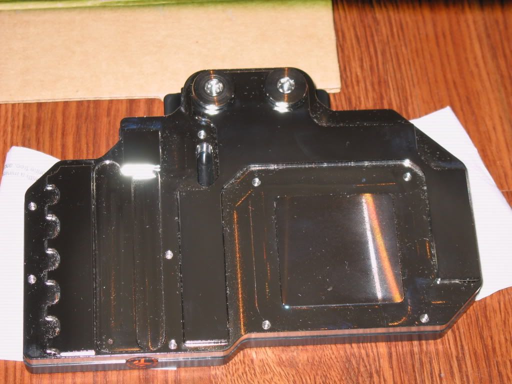
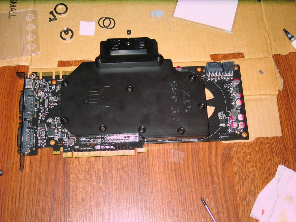
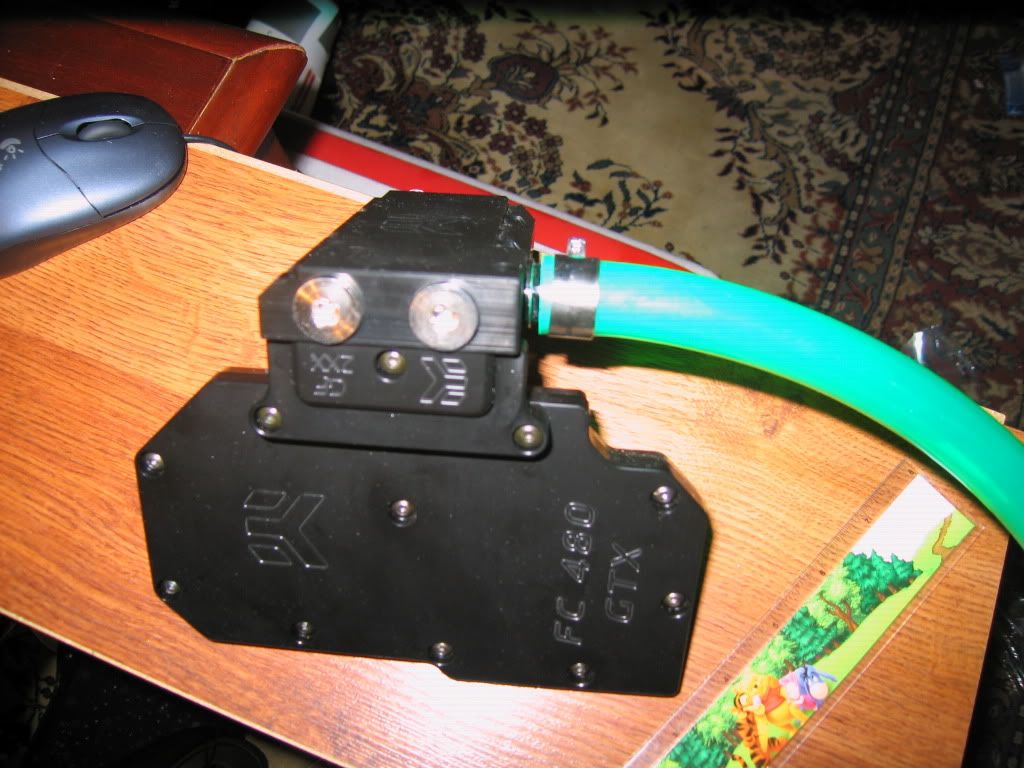
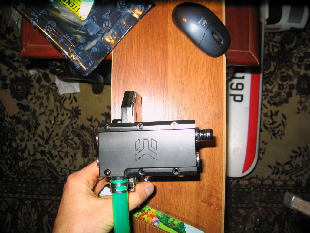
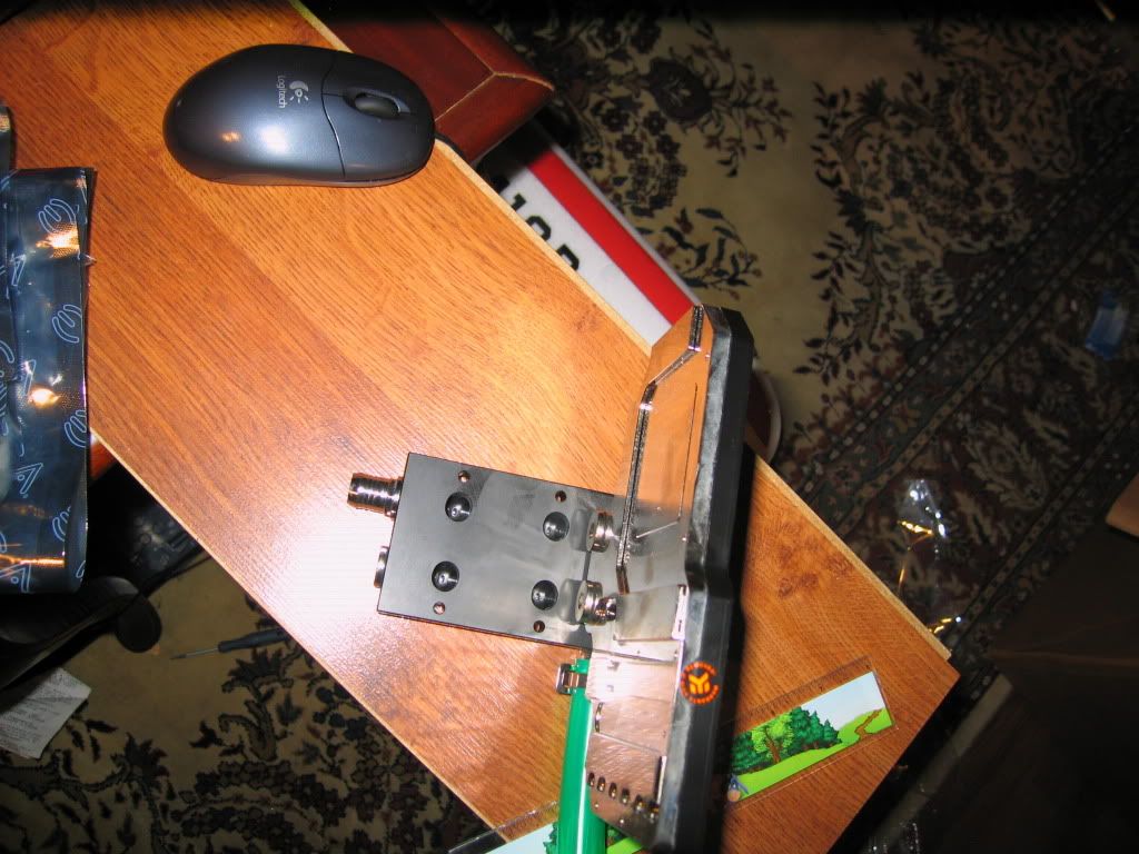
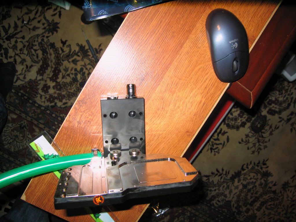
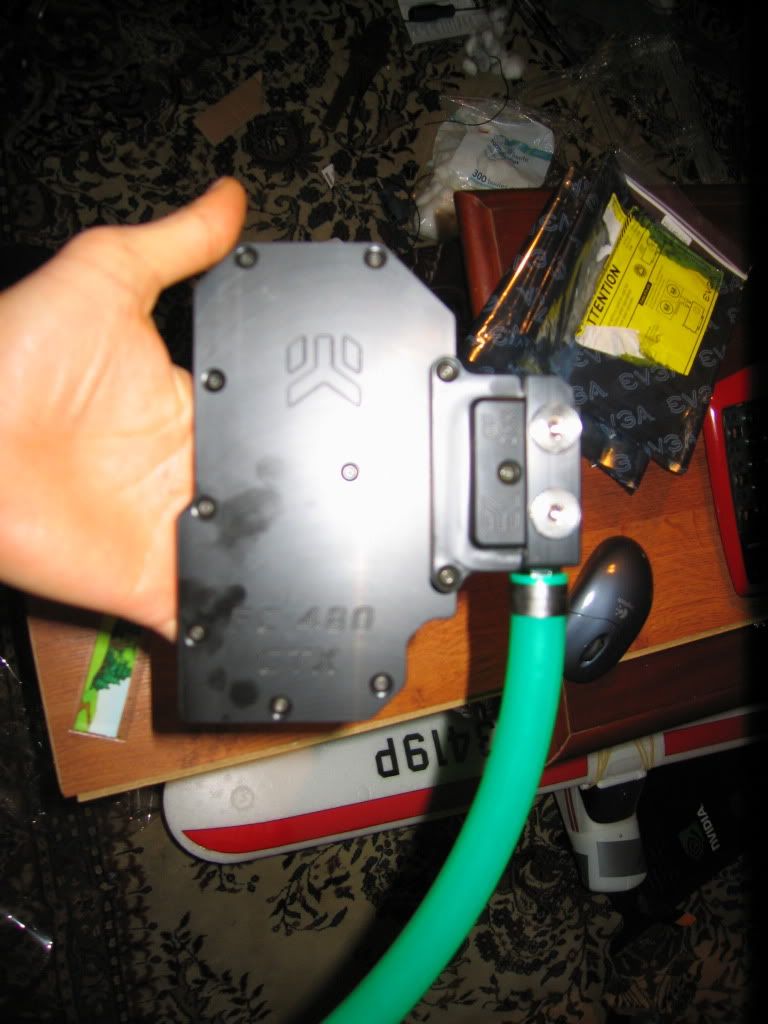
2 - Ek Nickel/POM GTX 480 Blocks
2 - EK GF200 LINKs
EK Triple Link Parallel
1/2" Promochill white tubing
1/2ID 3/4" OD Black Bitspower compression fittings (diff types and sizes)
Koolance TMS 200 and 200 expansion board
2 - Koolance Flow sensors INS-FM17
3 - Noise blocker PK-3 140mm Fans (1700rpm)
9 - Xigmatek 140mm fans 1000rpm (3 for pulling air, 6 used as shrouds)
4 - Antec 200mm Fans
9 - Coolermaster 120mm R4 Fans
Case:
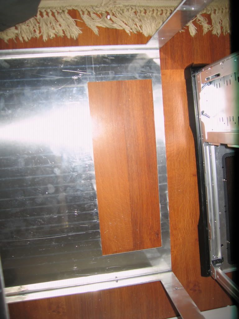
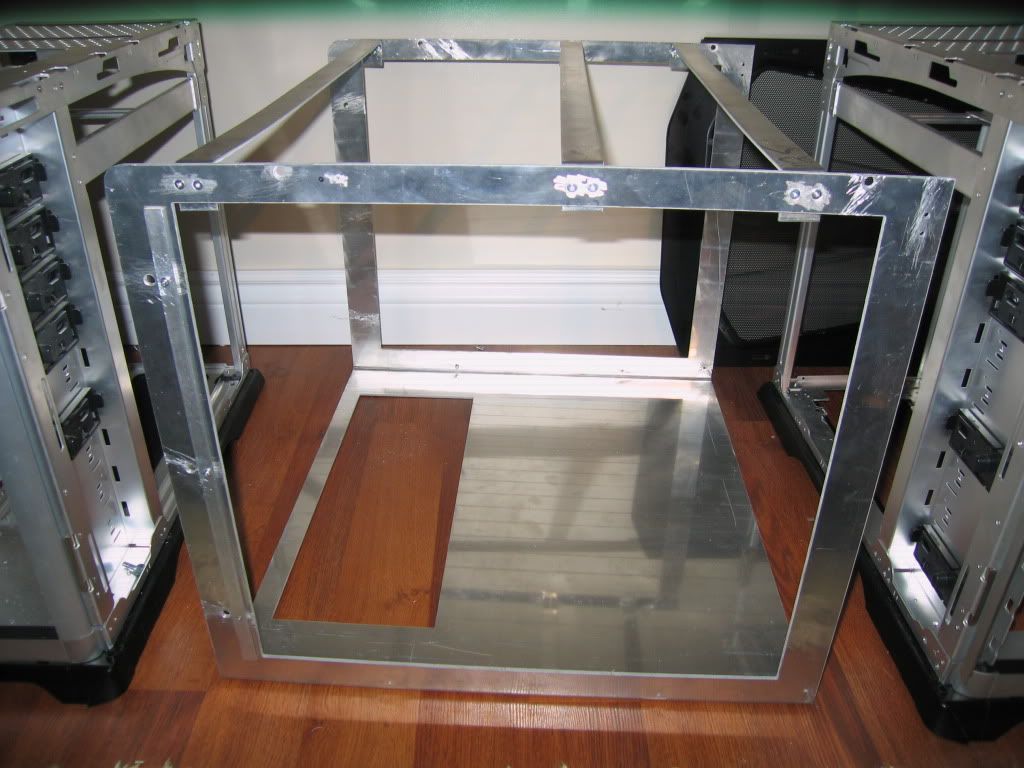
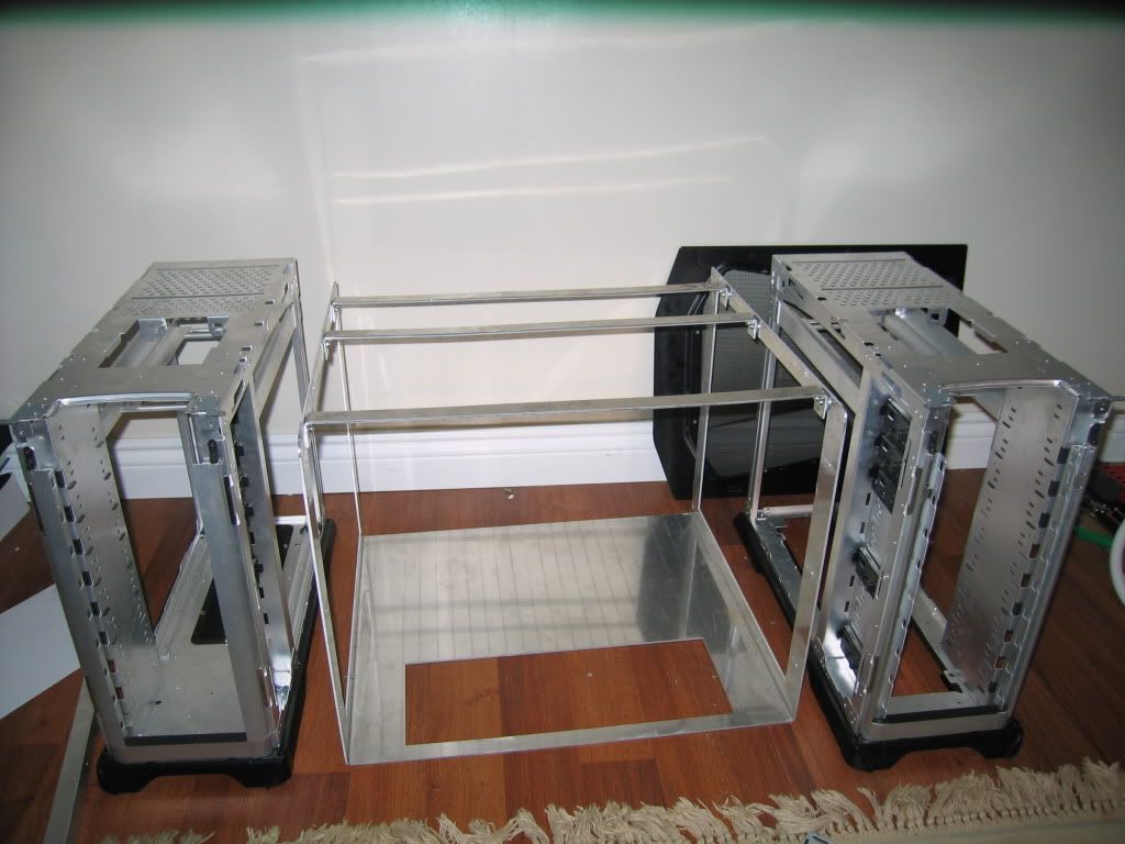
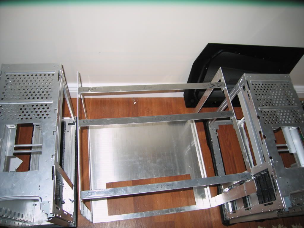
2 - Coolermaster Stacker 832 Cases
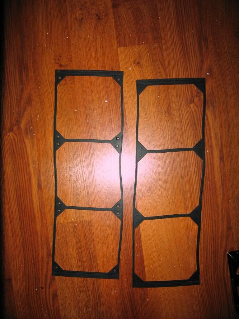
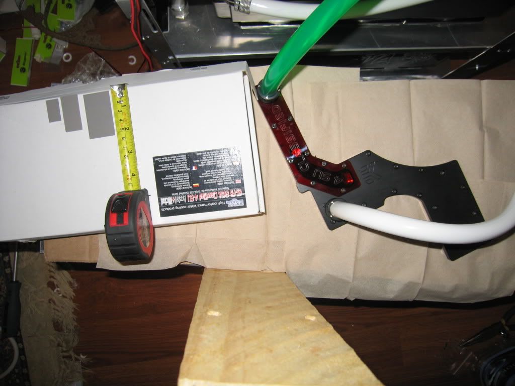
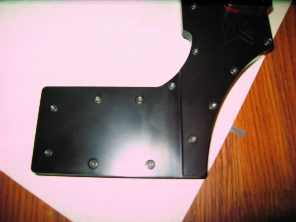
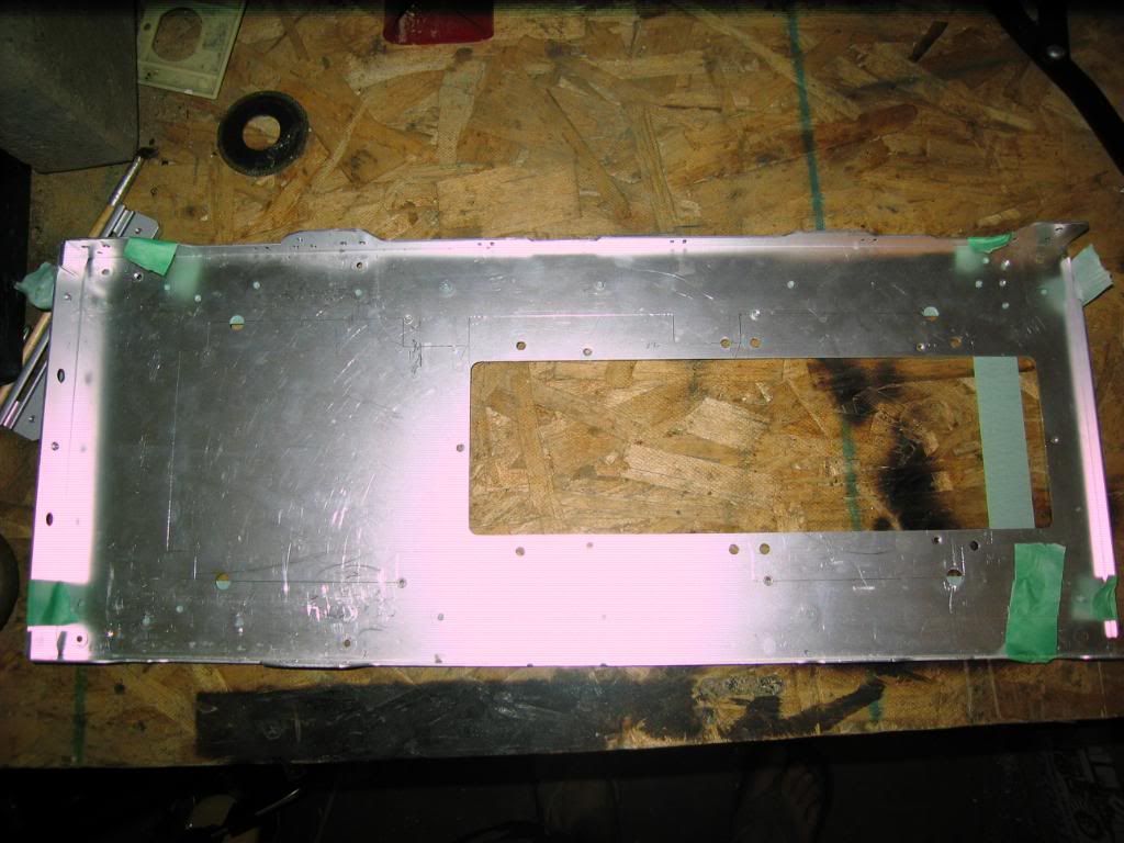
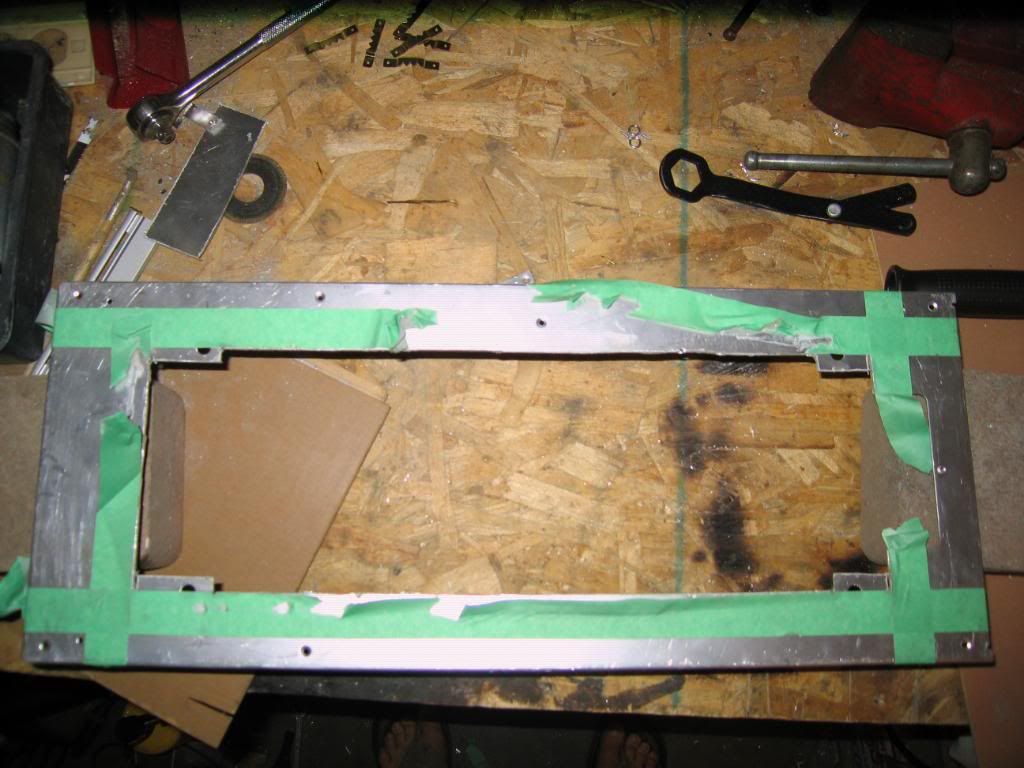
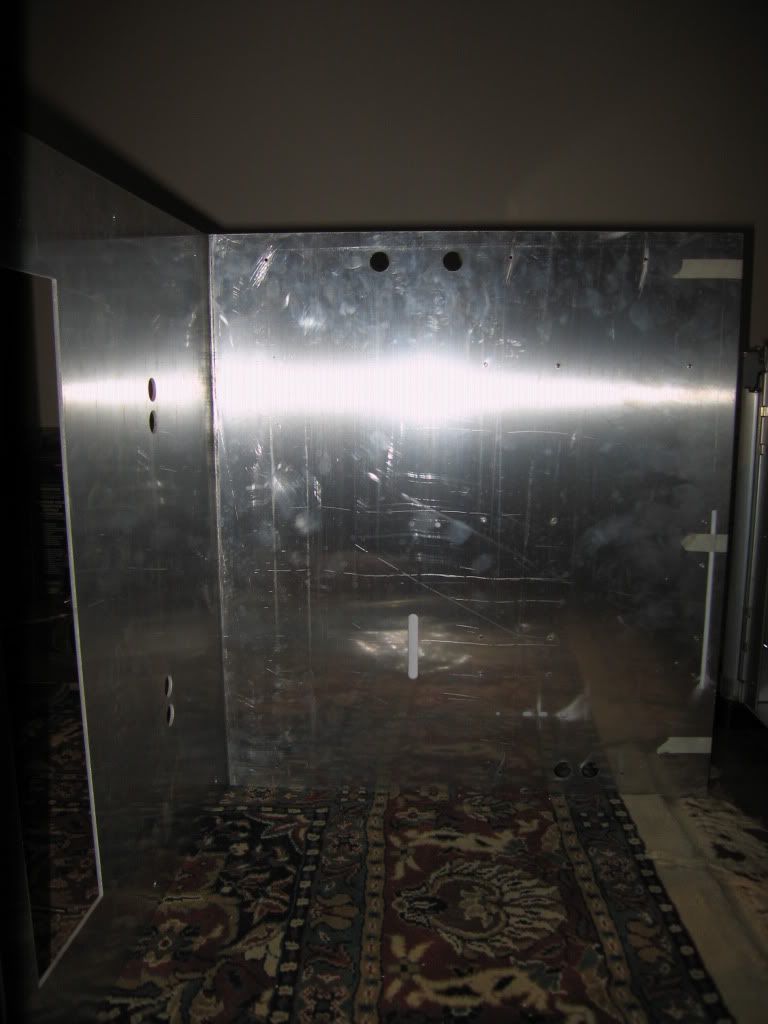
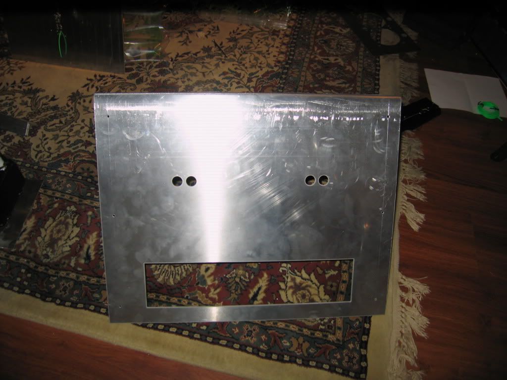
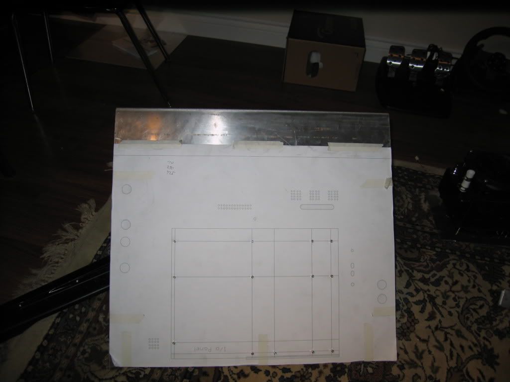
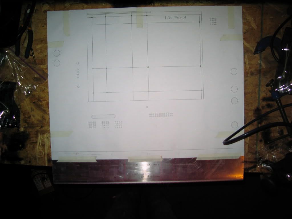
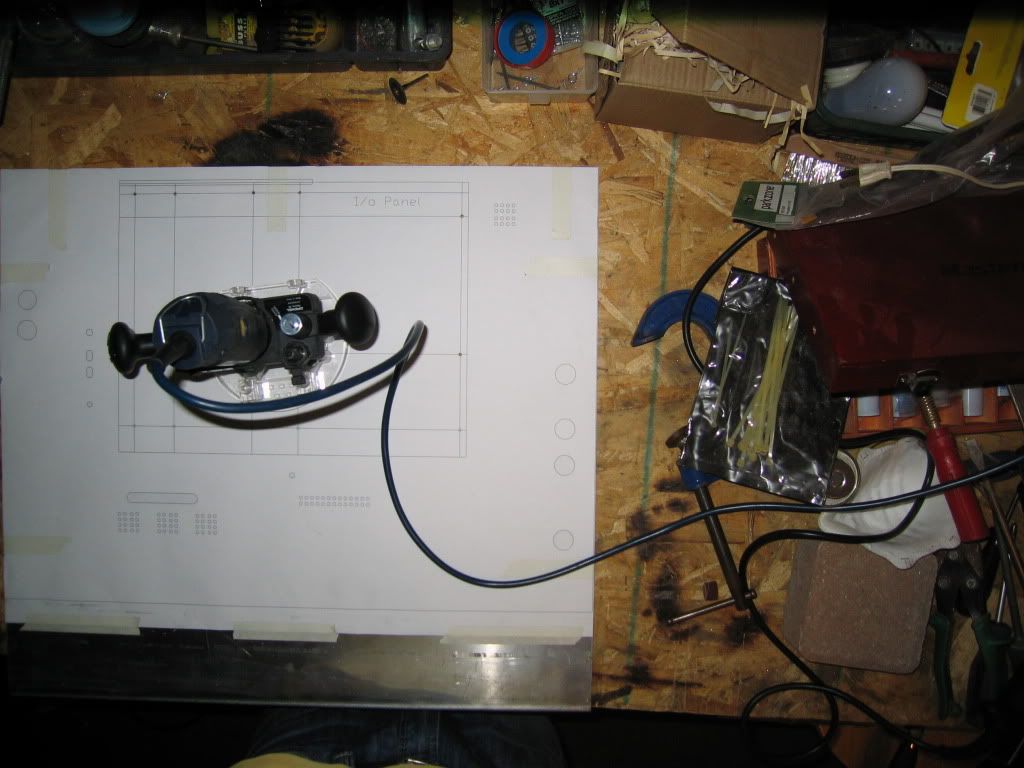
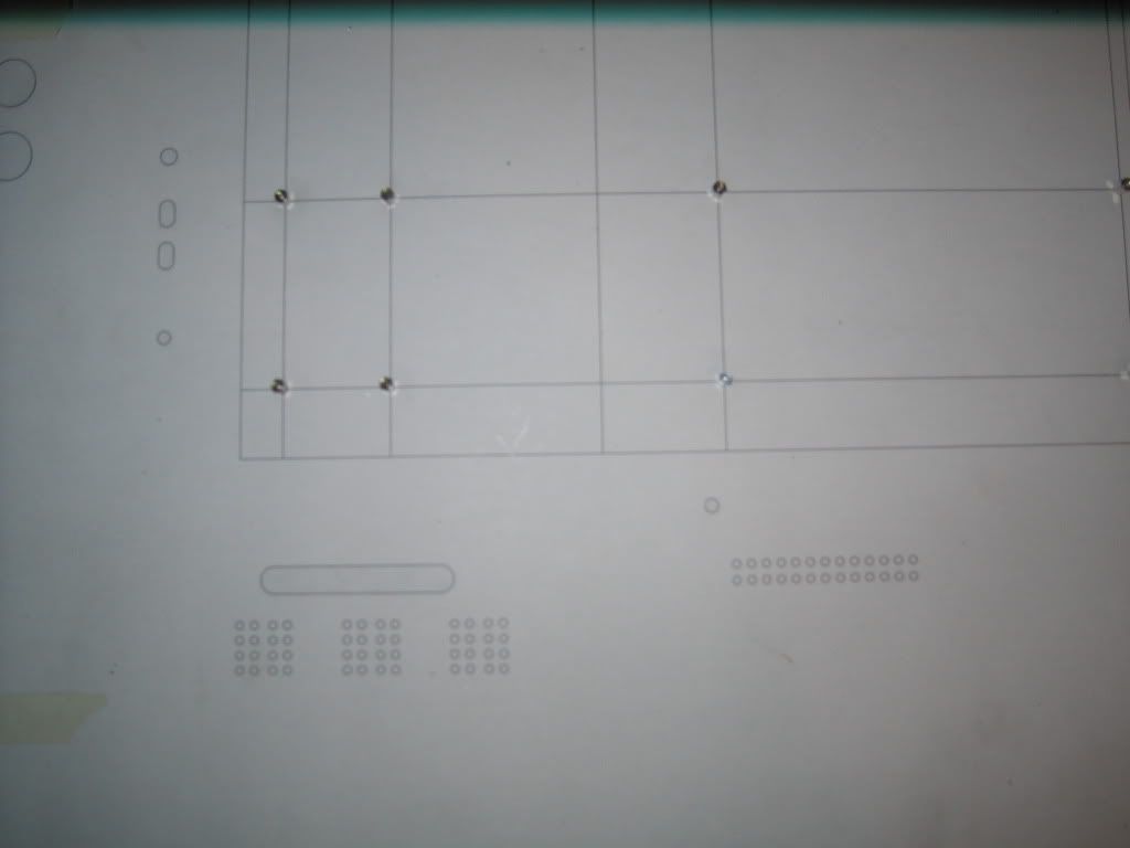
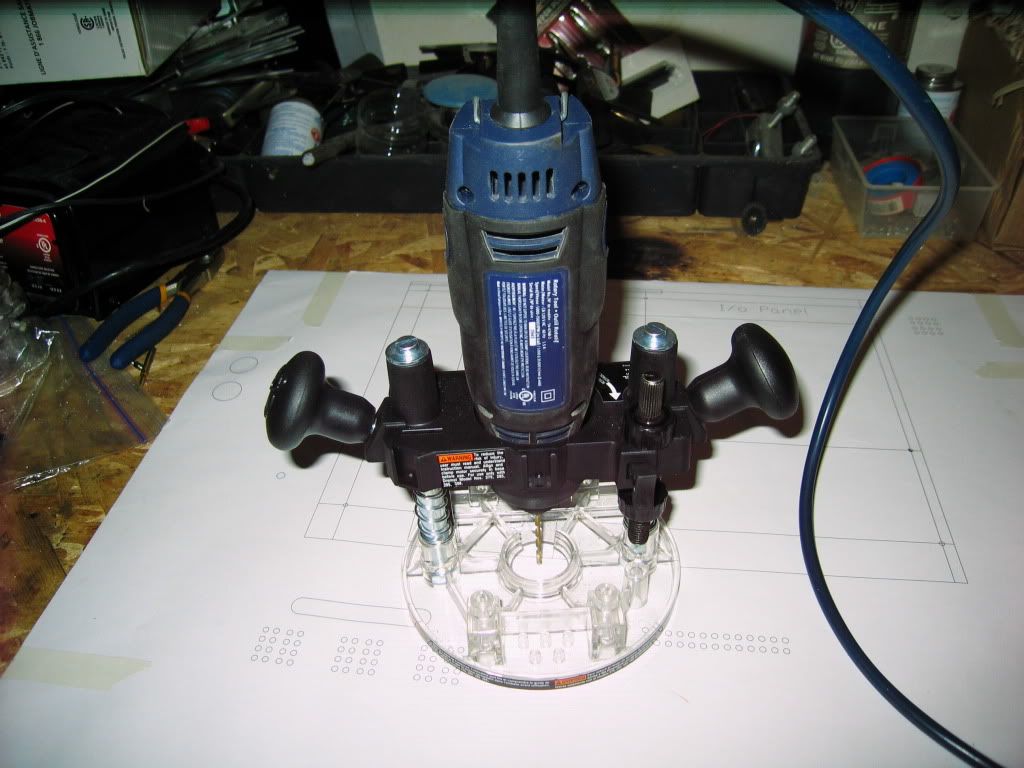
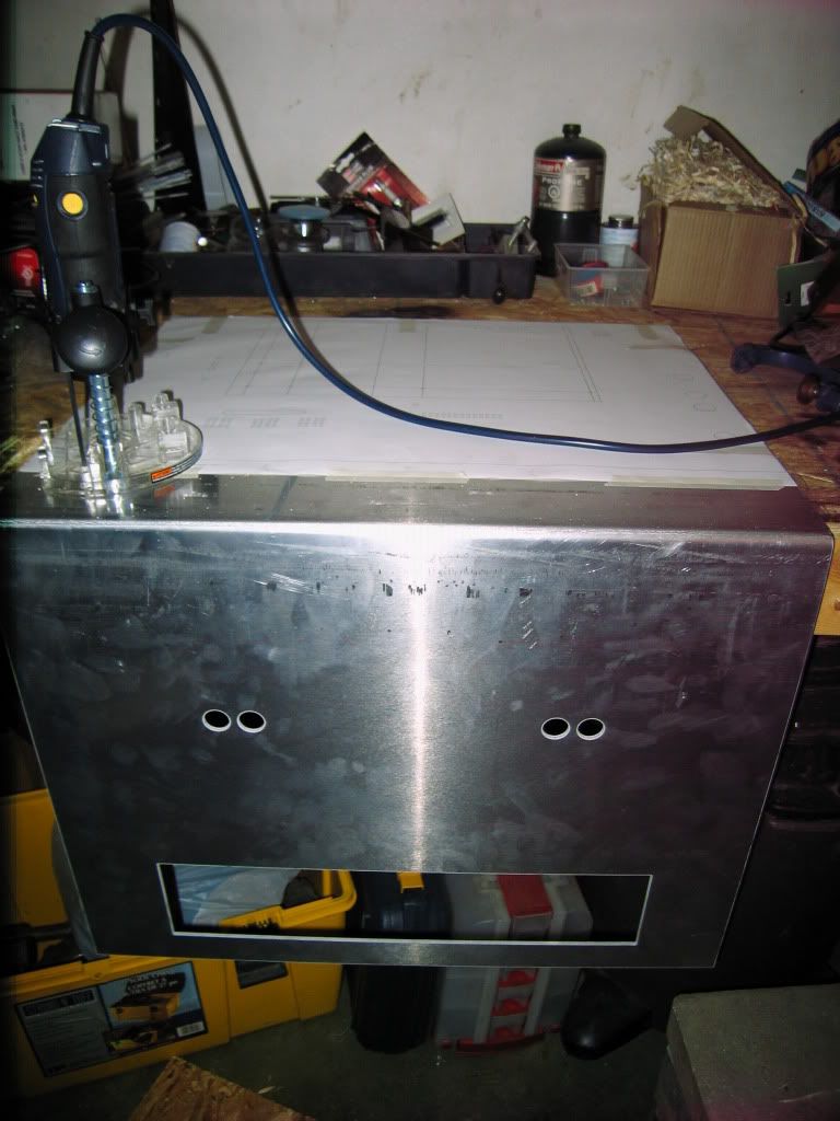
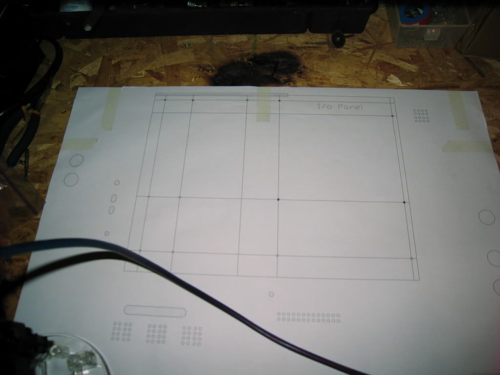
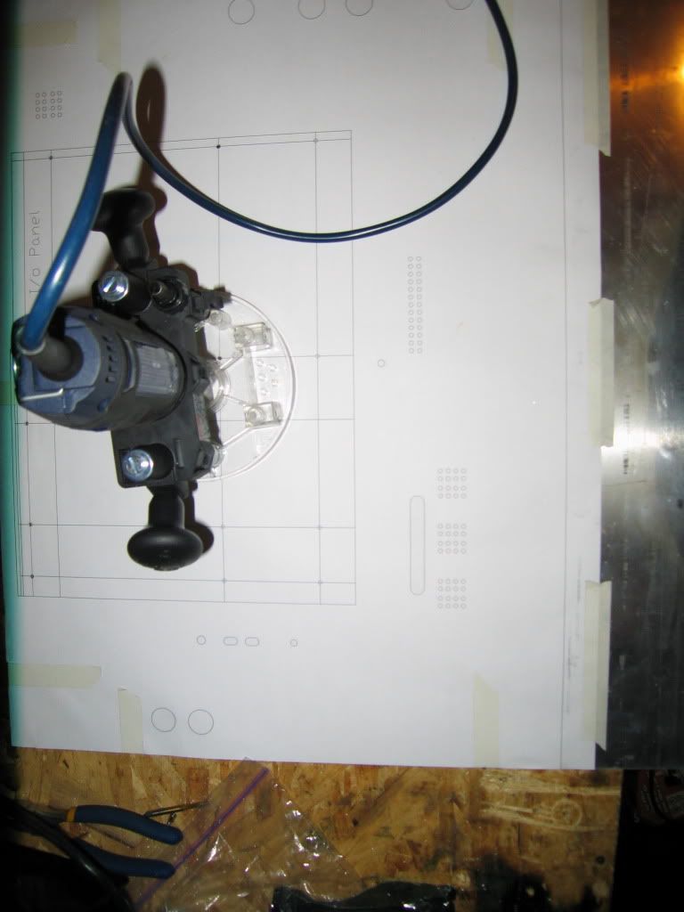
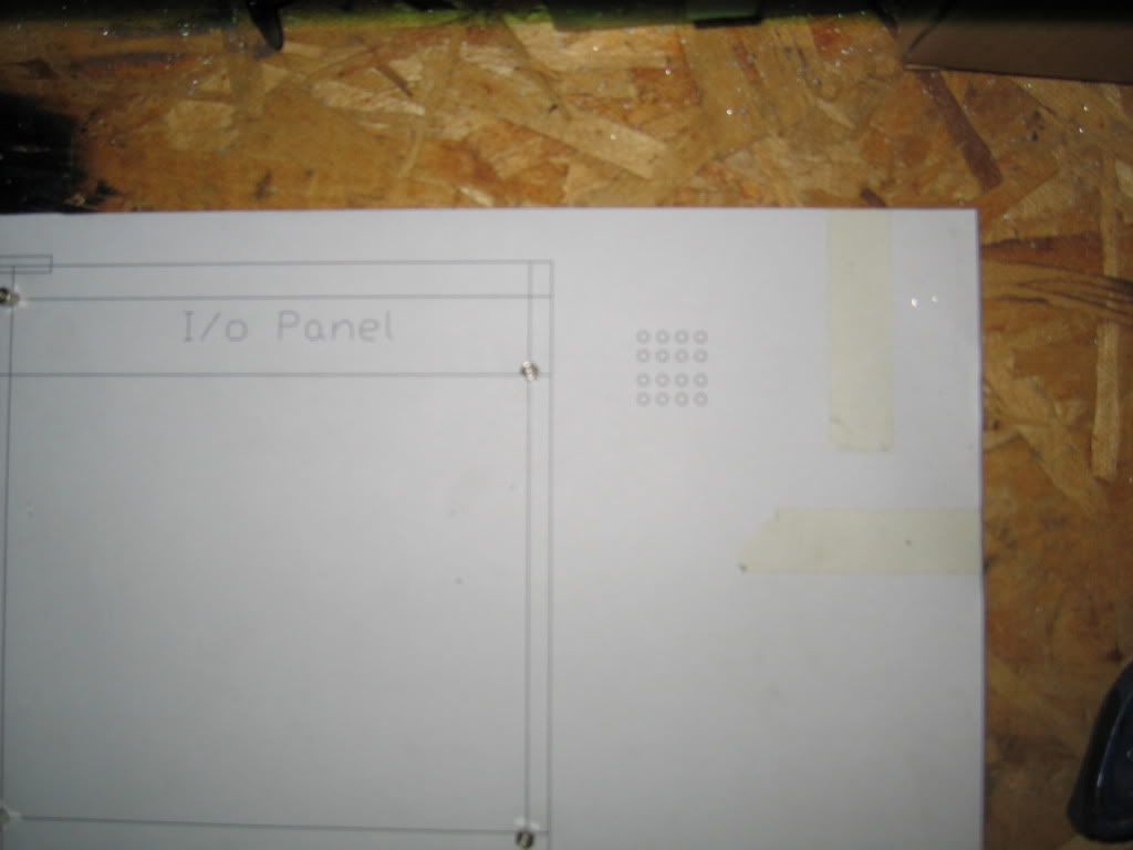
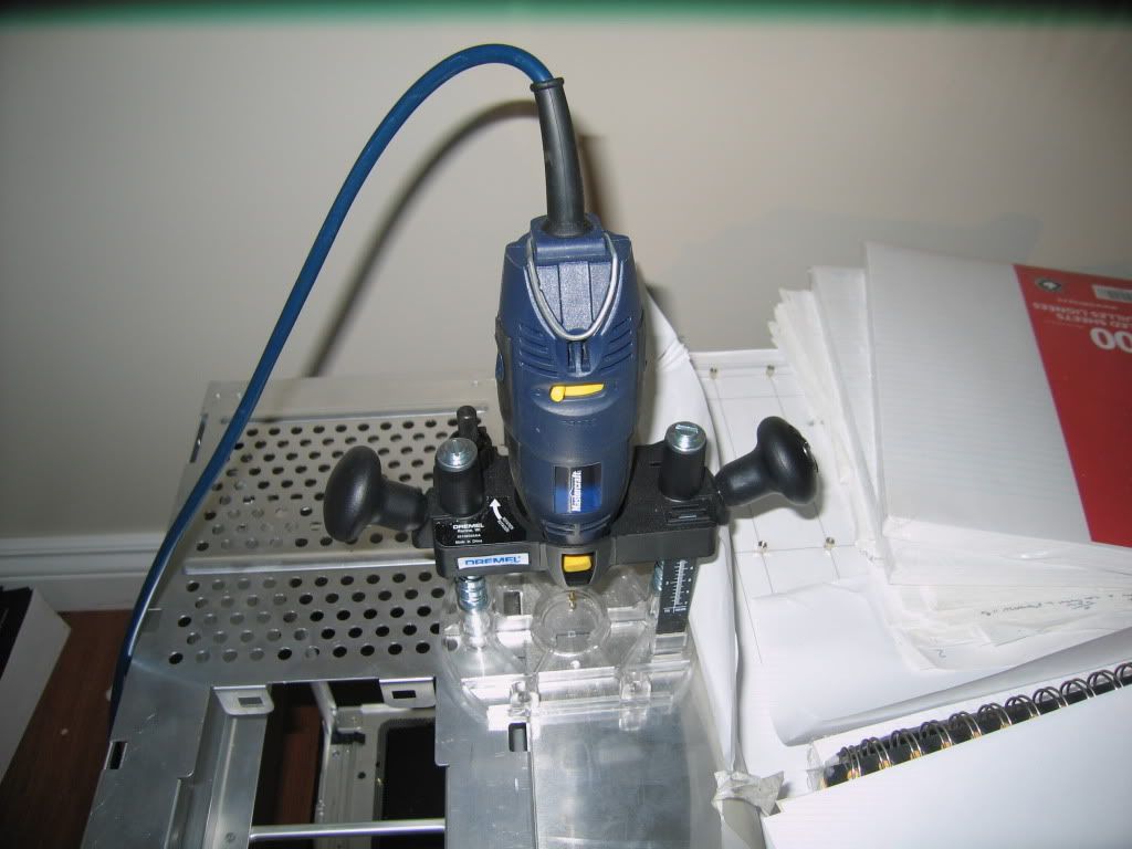
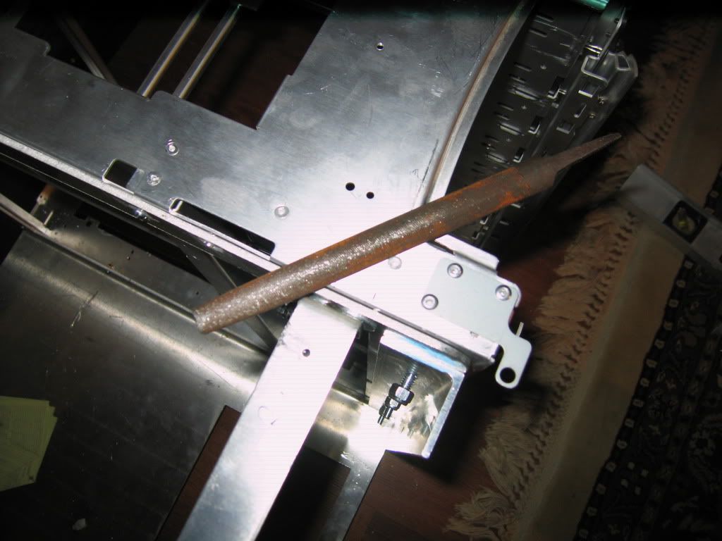
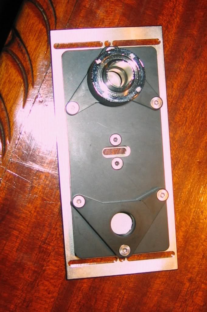
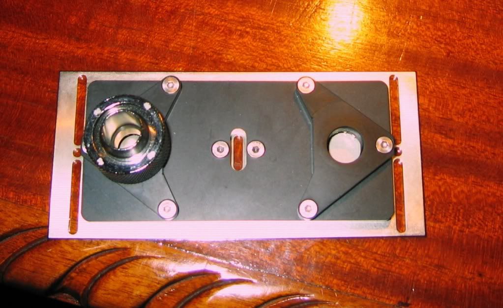
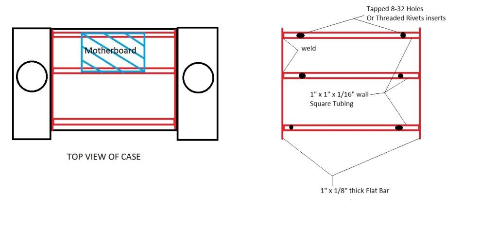
Custom waterjetted, bent and welded aluminum parts ( i will provide the CAD drawings for anyones use)
So thats the parts list for now, I am thinking of some editions with regards to sound card, low power vid card, usb 3.0 cards as well but I will post about those at a later date when the time is right
stay tuned, and i would appreciate your comments and insight
cheers
You can visit my entire post on EVGA FORUM - http://www.evga.com/forums/tm.aspx?high=&m=602083&mpage=1#602083
latest state of the build
VOTE FOR MY MODRIGS SETUP - CLICK THE LINK AND IF YOU LIKE THE SYSTEM, GIVE ME A +1
www.evga.com/ModsRigs/detail.aspx?BuildID=23510
Hi All
this is my first post to any forum, and 3rd attemp on here, stupid thing keeps deleting my post, ugh, bang head, bang head!!!
well im going to start off by saying this is a post for the build log of my new custome case/system which im calling FERMI 2
It was supposed to be called FERMI 3 but i sold off my FTW 480 today (money constaints).
the case is made out of 2 coolermaster stacker 832 cases
which i think you guys will like I have went through many revisions of this case and now have finally found one i like and that works well which is REV 4 right now
WHY I CHOSE TO CALL MY SYSTEM/CASE FERMI 2
Fermi is the name of a Nuclear power plant. I live in Windsor, Ontario Canada which is located across from Detroit, Michigan. Now there is an actually power plant near windsor and detroit (10-20 miles away) called FERMI 2. Its a nuclear power plant
since each gtx 480 is from the Fermi Family, I decided to call it FERMI 2. Ill be using 2 corsair 850w power supplies (2 generators), so Ill be putting 1700W or 1.7kW Capacity on the case
maybe with red leds behind an engraved acrylic panel Now if i decide to buy a 3rd GTX 480 (just sold my third one
... ) than ill be naming it FERMI 3.Now there are 2 Fermi Cards (reactors), 2 cooling towers (2 radiators), 2 dump tanks (used for emergencies) (2 reservoirs), the the whole theme goes well with the case.
Let me know what you think.....
so
the system consists of the following:
Hardware:
Core i7 930
EVGA X58 4 way sli Mobo
Corsair Dominator GT 2000c7
2 - EVGA GTX 480's Super Clocked editions
1 - Corsair HX850w power supply
1 - Corsair AX850w power supply (will get it in 2 weeks as i sold one of my two hx850's that was with my HD5970 build)
Watercooling:
Feser 420 Monsta Radiator
Feser 360 Xchanger Radiator
2 - Swiftech MCP-655 Pumps
2 - EK MCP-655 X-TOP Ver. 2
2 - Koolance 120mm Reservoirs
EK Supreme HF cpu block (black + nickel)
EK Classified 4 way Full Motherboard Block
MIPS computer Corsair 6 Ram Block
2 - Ek Nickel/POM GTX 480 Blocks
2 - EK GF200 LINKs
EK Triple Link Parallel
1/2" Promochill white tubing
1/2ID 3/4" OD Black Bitspower compression fittings (diff types and sizes)
Koolance TMS 200 and 200 expansion board
2 - Koolance Flow sensors INS-FM17
3 - Noise blocker PK-3 140mm Fans (1700rpm)
9 - Xigmatek 140mm fans 1000rpm (3 for pulling air, 6 used as shrouds)
4 - Antec 200mm Fans
9 - Coolermaster 120mm R4 Fans
Case:
2 - Coolermaster Stacker 832 Cases
Custom waterjetted, bent and welded aluminum parts
( i will provide the CAD drawings for anyones use) So thats the parts list for now, I am thinking of some editions with regards to sound card, low power vid card, usb 3.0 cards as well but I will post about those at a later date when the time is right
stay tuned, and i would appreciate your comments and insight
cheers
Last edited: