![]() |
|
#1
|
|||
|
|||
|
Project: PrometheusCu
![]() Sponsored by: AquaComputer ![]() Watercool: ![]() MIPS Computer GMBH ![]() Corsair ![]() This is my first real desktop mod, and it's been long in planning. Now that most of my components have arrived and some progress has been made I've decided to share what I've created so far. The concept behind this case is to design a simple elegant case jam packed with technology, toys, and a powerful watercooling setup. 
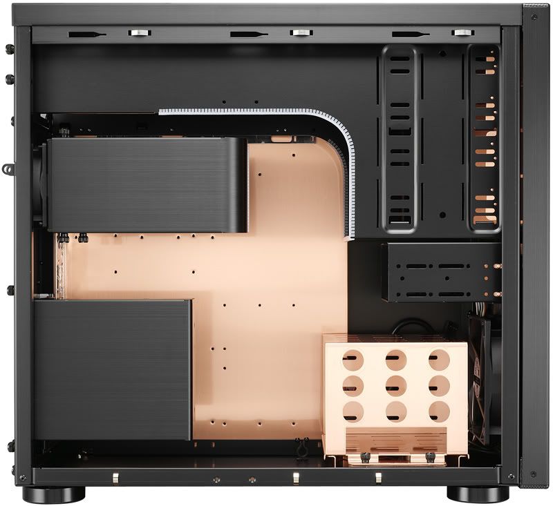
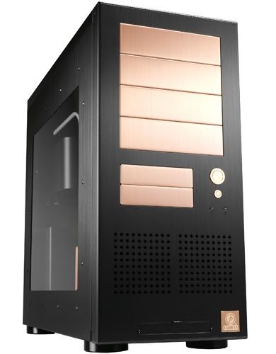
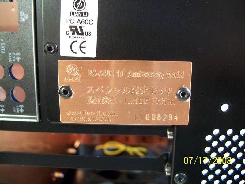
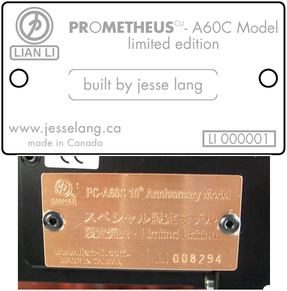
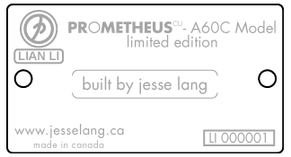
The idea for the design was directly inspired by the case I started with, a 10th Anniversary Lian-Li PC-a60c: *click for big* ![]() ![]() 
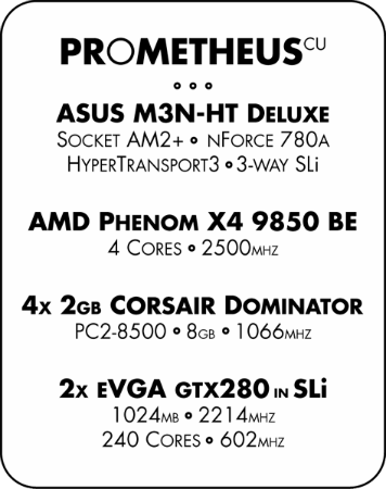
First I'll outline the system components I'll be using: Main System Lian-Li PC-A60C 10th Anniversary #294 of 300 
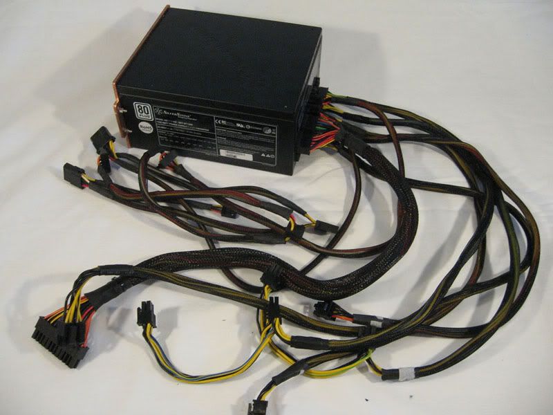
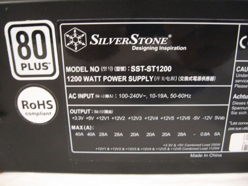
Silverstone Strider 1200W Modular ATX 
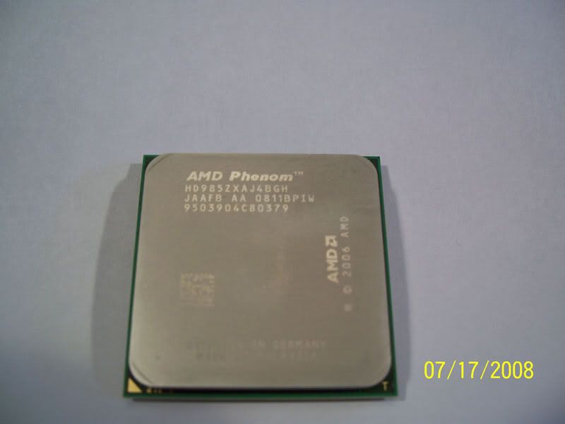
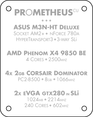
AMD Phenom X4 9850 BE Quad Core AM2 2.5GHZ 
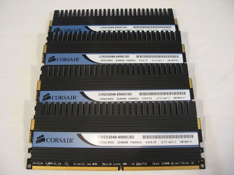
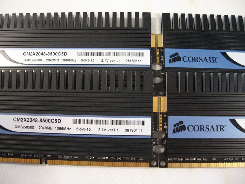
Corsair Dominator PC2-8500 5-5-5-15 8GB (4x2GB) 
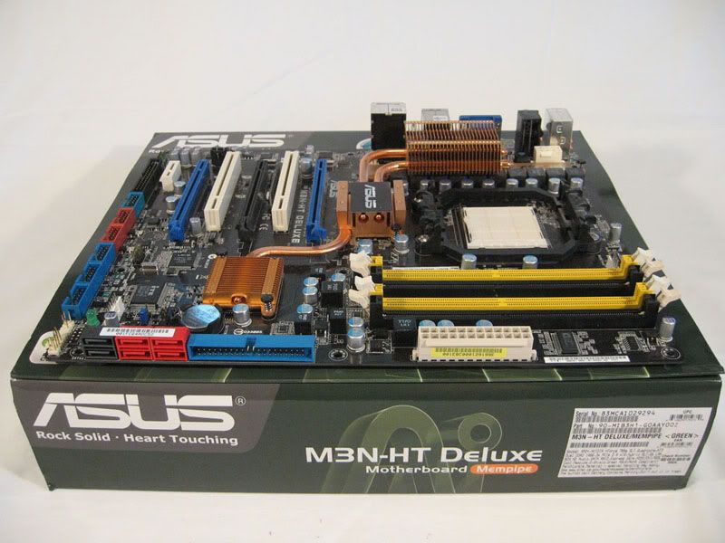
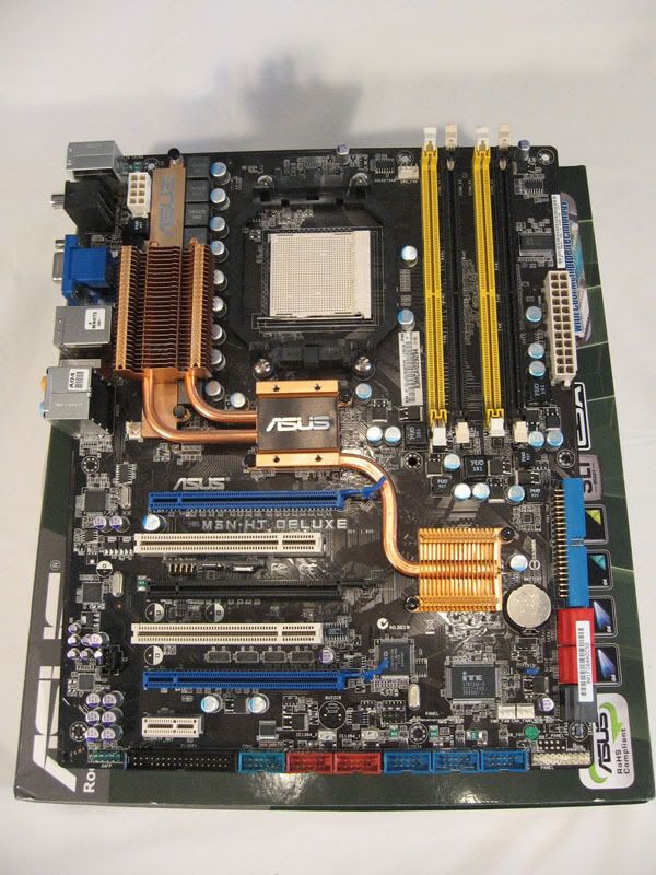
ASUS AM2+ M3N-HT Deluxe Mempipe 3-way SLI 2x EVGA E-geForce GTX 280 SSC 648MHZ 1024MB 2.322GHZ Secondary System VIA ARTiGO Kit A1000 C7 1GHZ 1GB DDR2 OCZ 1GB DDR2 SODIMM PC2 PC-5400 667Mhz Fujitsu 2.5" IDE 5400RPM 120GB 
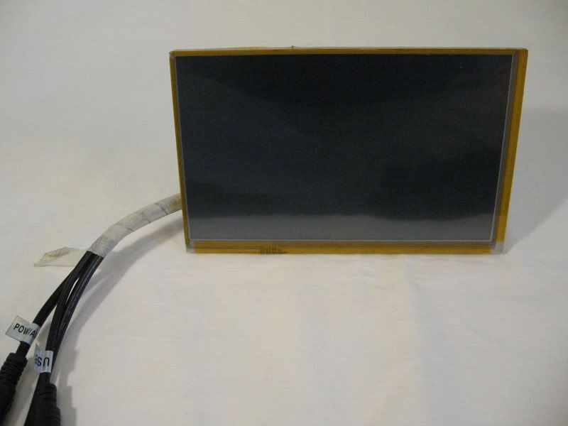
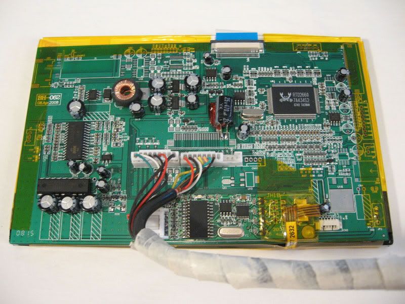
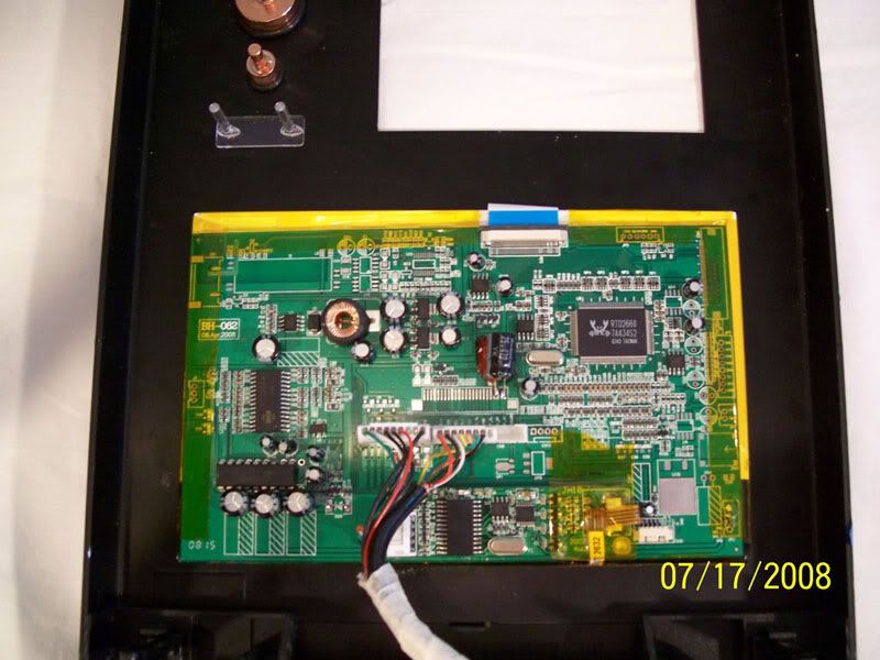
XDX 7" VGA Touch Screen TFT LCD 1024x768 Router/Firewall 
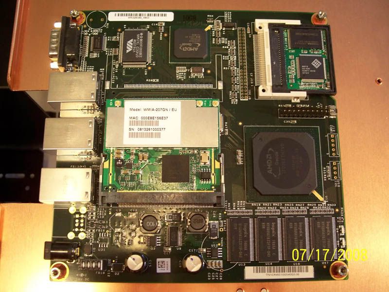
PCEngines ALIX.2C1 Kit 3x10/100LAN SparkLAN WMIA-207GN WLAN 802.11n Mini PCI 1GB Type 6 Compact Flash Storage/Media 
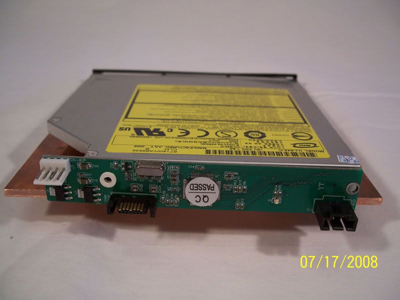
Pioneer Slim 8X DVD+/-RW Slot Load Slim CD/DVD-ROM to SATA Adapter 4x Hitachi 3.5" SATA 7200RPM 750GB 3x LaCie Neil Poulton eSATA 7200RPM 750GB External Lian-Li Aluminum 50-in-1 Card Reader Additions Mini Nova USB Bluetooth Adapter Zalman Plus Multi Fan Controller 
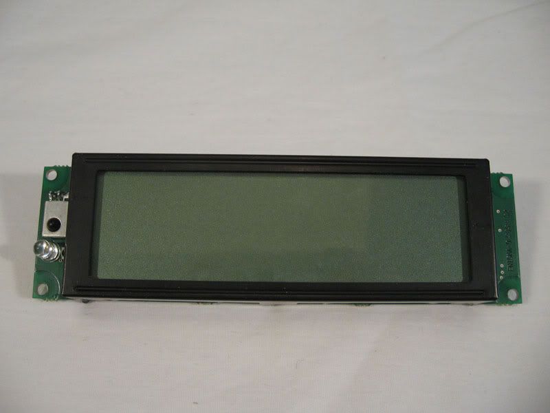
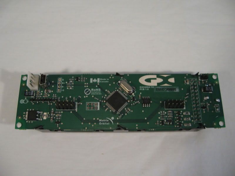
Matrix Orbital GX Typhoon USB TRI-LED LCD 240x64 2xNexxtech mini 4 Port USB Hub AquaComputer multiswitch USB 1.41 AquaComputer aquaero 4.00 USB Air Cooling 
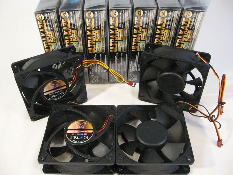
6xScythe Ultra Kaze 120mm x 25mm 133.60CFM 1xScythe Kama-Flex 80mm x 25mm 34.0CFM 9xScythe Mini Kaze Ultra 40mm x 20mm 4.86CFM Watercooling 
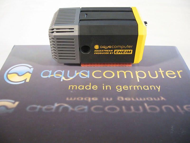
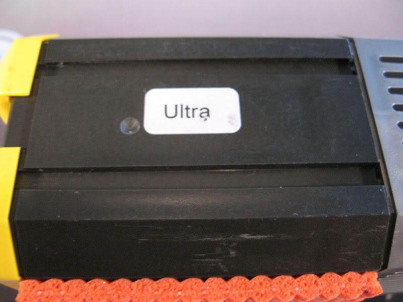
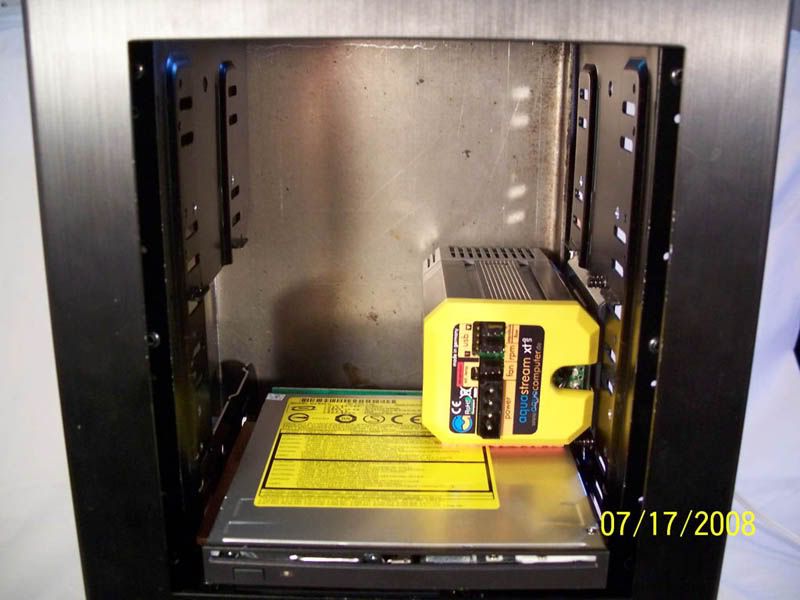
Aqua Computer Aquastream XT Ultra USB Eheim 12 V 
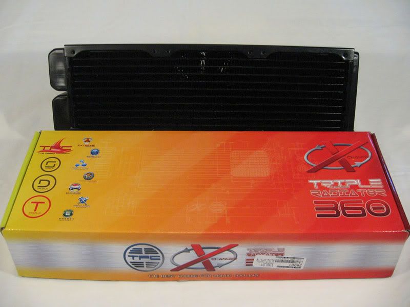
Feser XChanger Triple 120mm Xtreme D-TEK FuZion V2 Socket AM2 Waterblock D-TEK FuZion v2 Quad Core Mid Chamber Insert Mips Ram Freezer 4 Ram Waterblock Nickel Edition 2xAquaComputer G200 waterblock for GX280 AquaComputer Durchflusssensor (Flow Sensor) 6xAquaComputer Rotary elbow adapter G1/4 AquaComputer aquaero/aquastream XT temperature sensor 70 cm Danger Den Cooling System Fillport Black Primochill Primoflex Pro LRT Black 1/2IN ID 3/4IN OD Tubing 20x Bitspower G1/4 High Flow 1/2IN Dark Nickel Plated Barb Fittings 
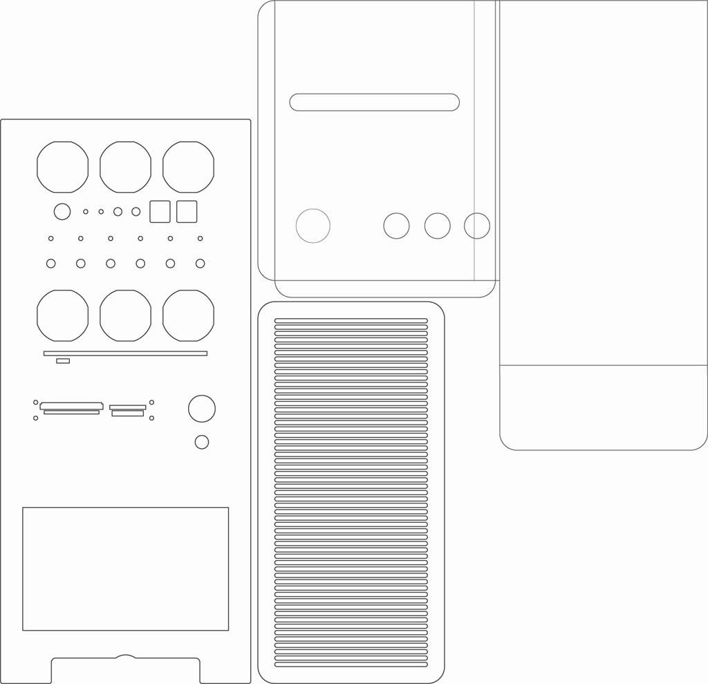
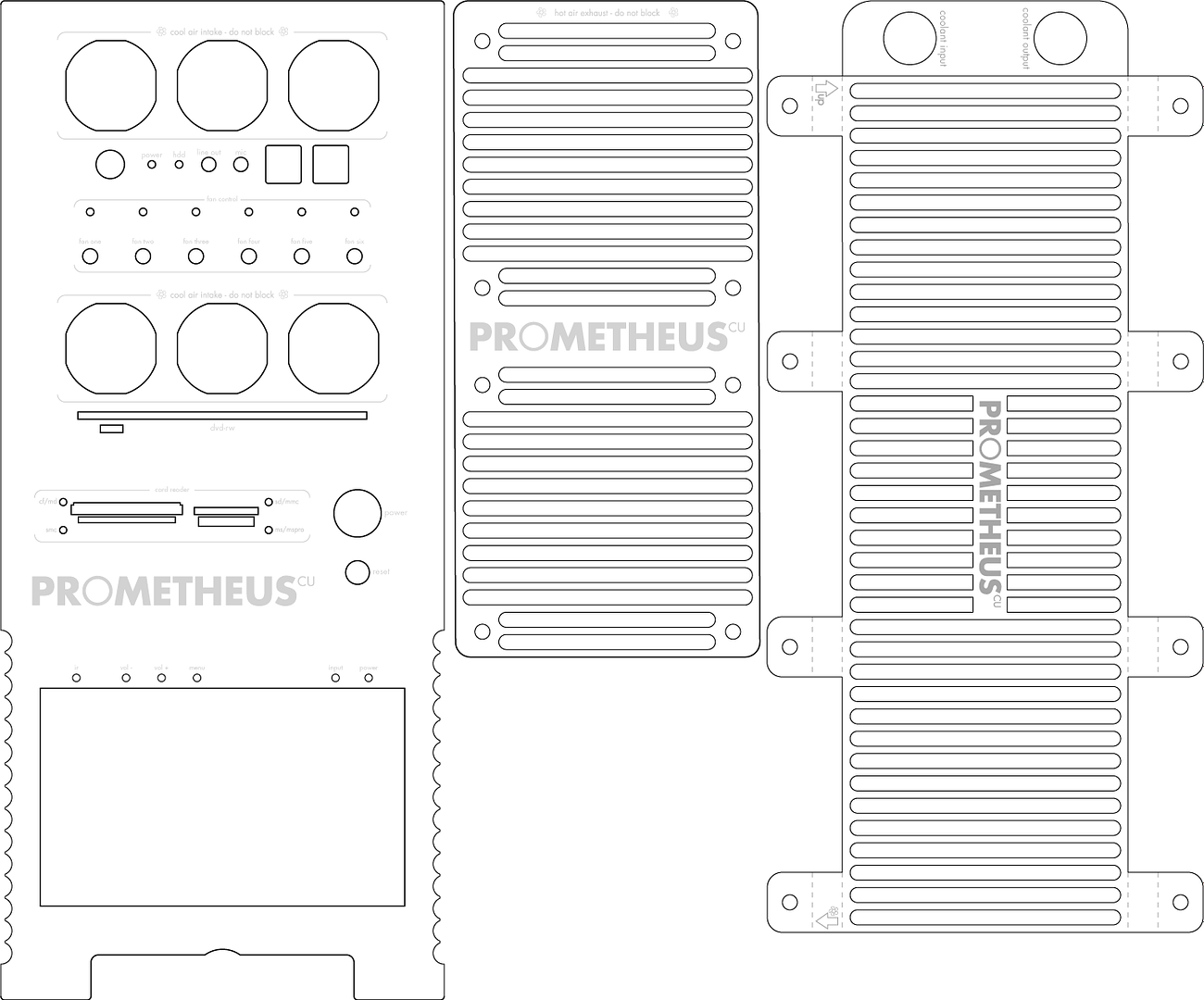
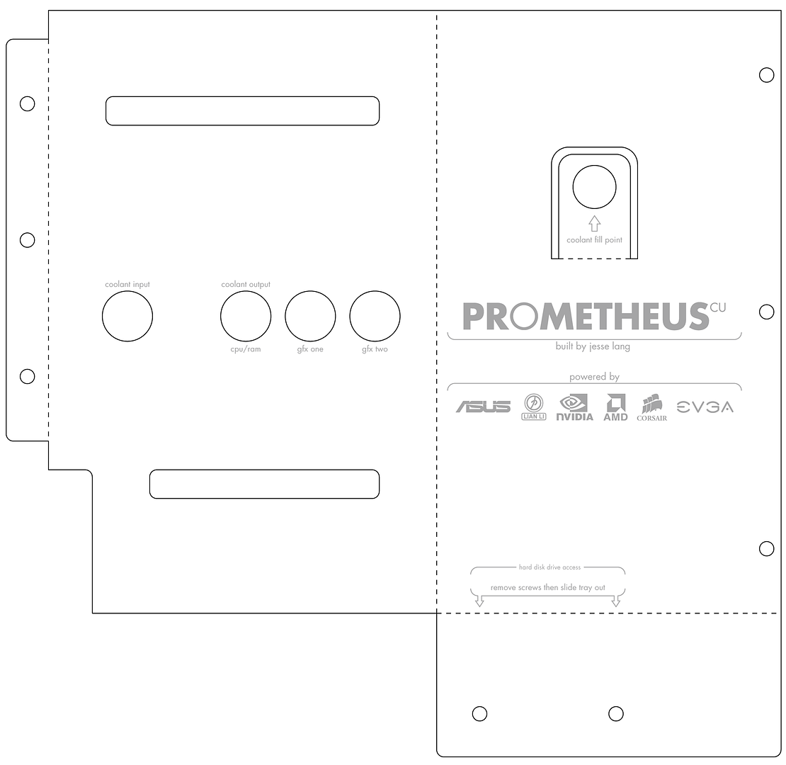
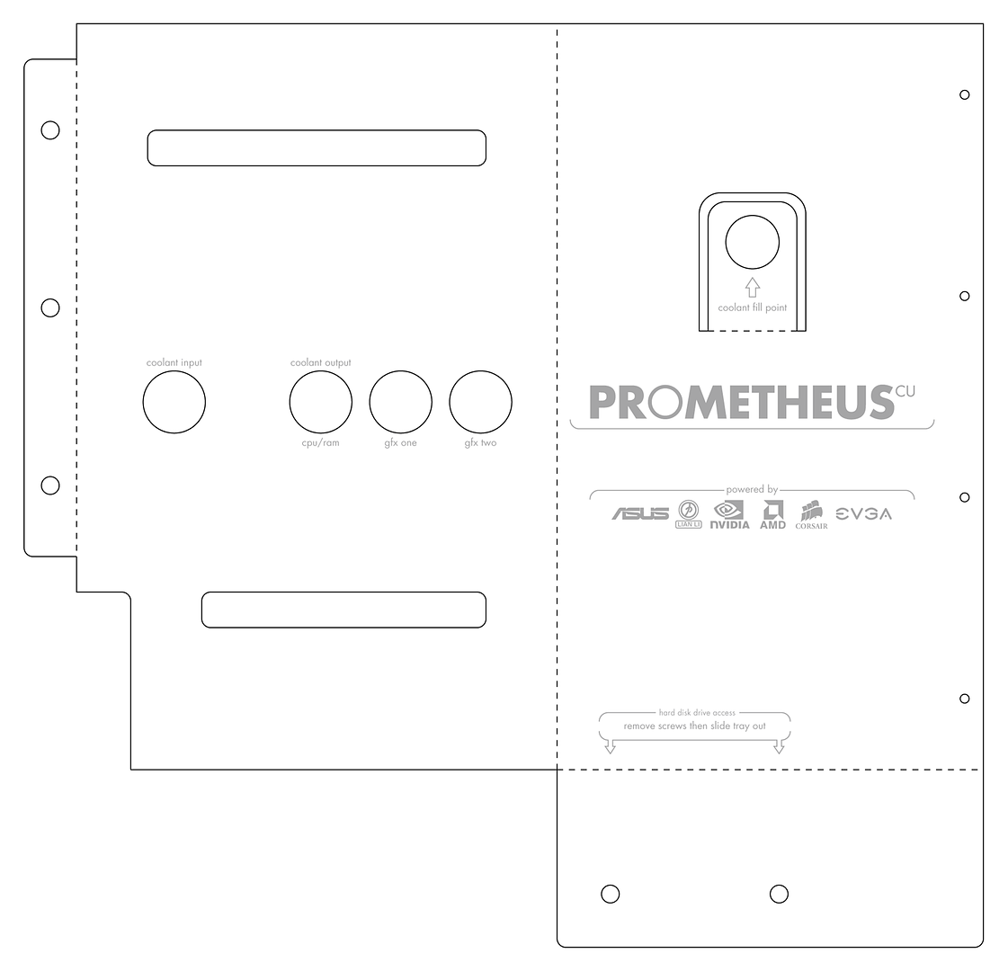
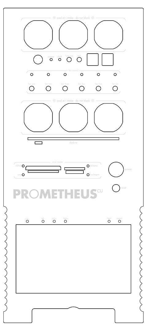
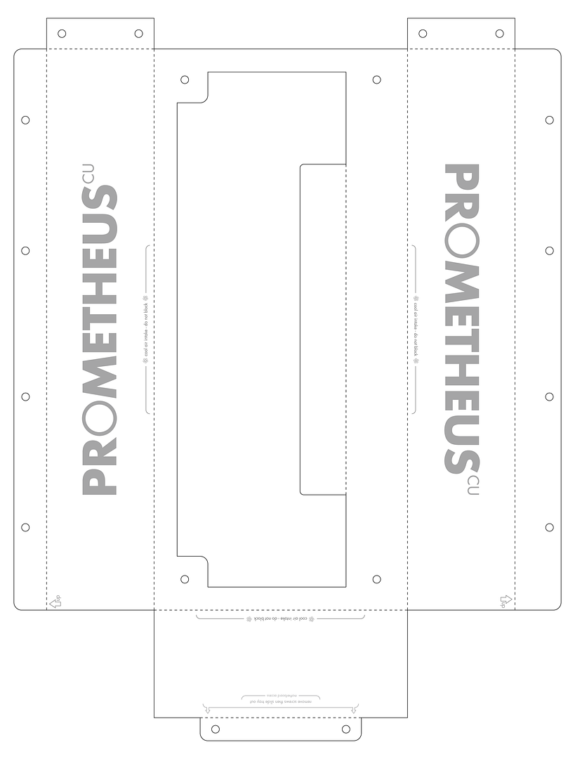
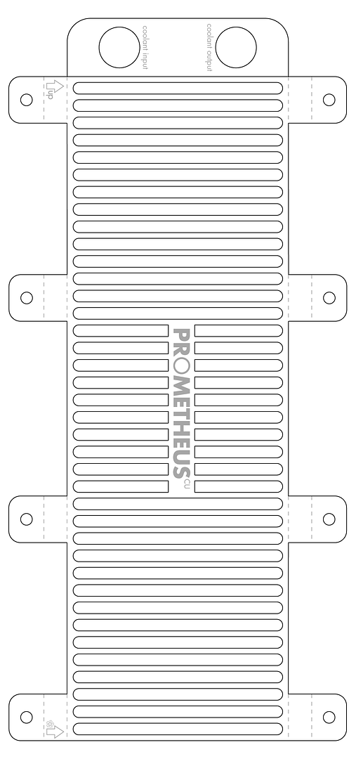
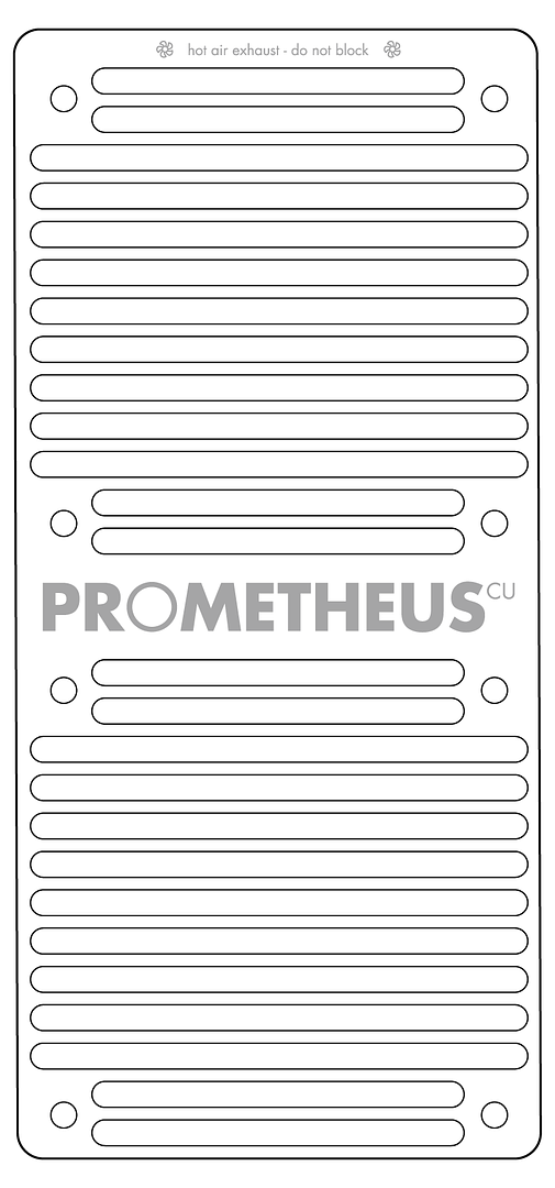
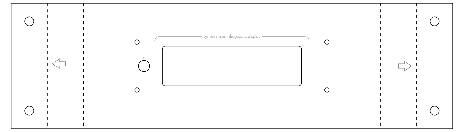
Here is a rough concept of the design plans: *click for big* 
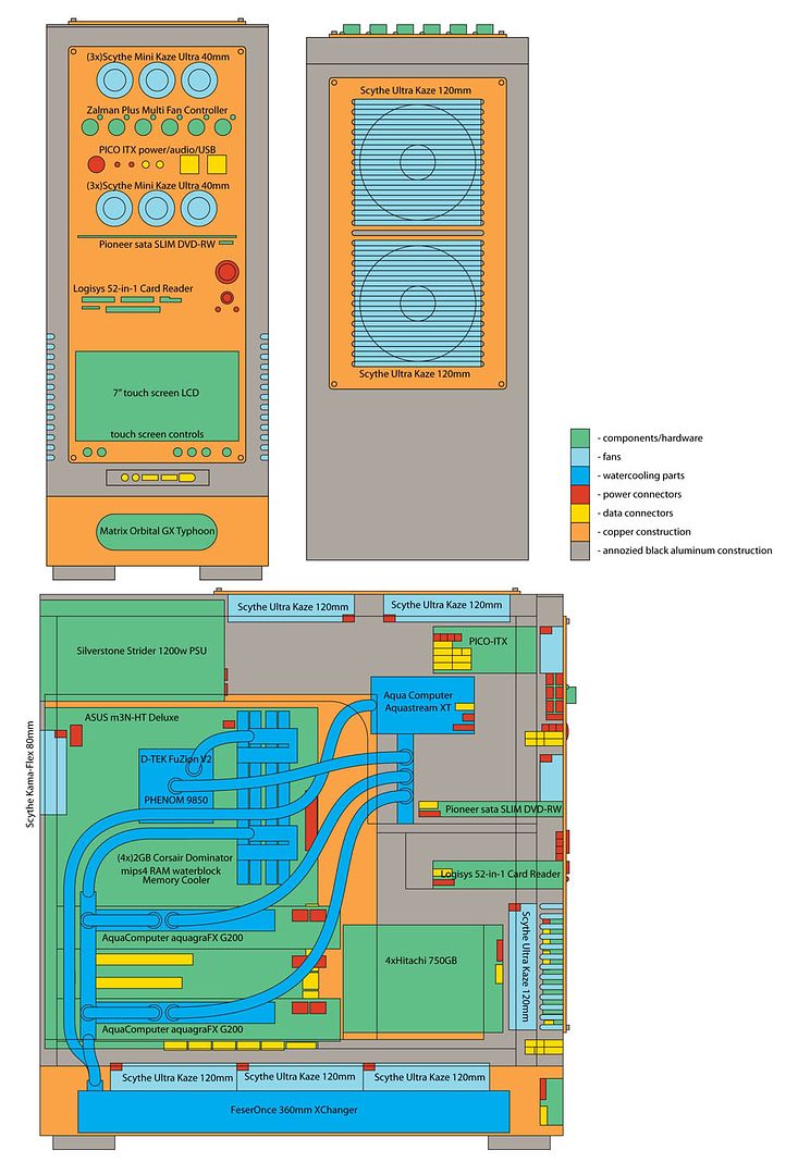
Rough Designs for the front panel, top panel, and dive bay enclosure panel ![]() Now onto part pictures: *click for big* AMD Phenom 9850 BE ![]() Asus M3N-HT ![]() 
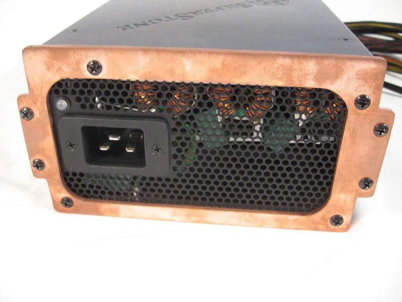
SilverStone Strider St1200 1200Watt ![]() Corsair Dominator RAM
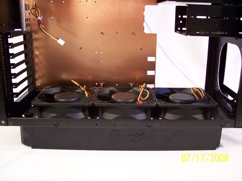
 ![]() The 120mm Fans The MO TyphoonGX tri-colour 
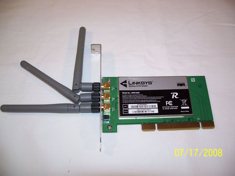
The Linksys WIFI-n card for bypassing the emedded firewall ![]() I'm sorry I diddn't take any progess pics so-far but I'll be doing so from here on out. 
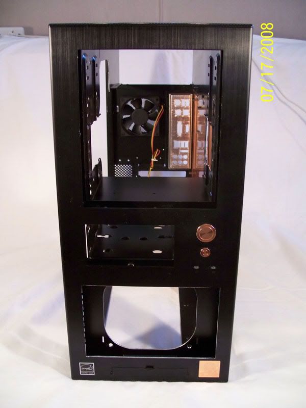
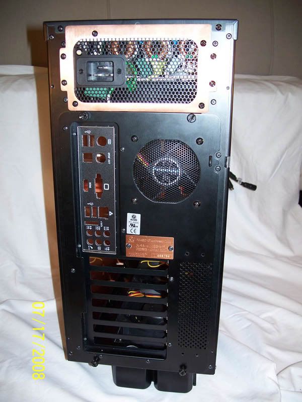
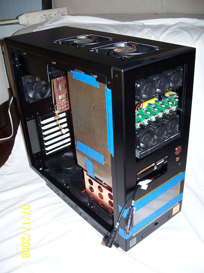
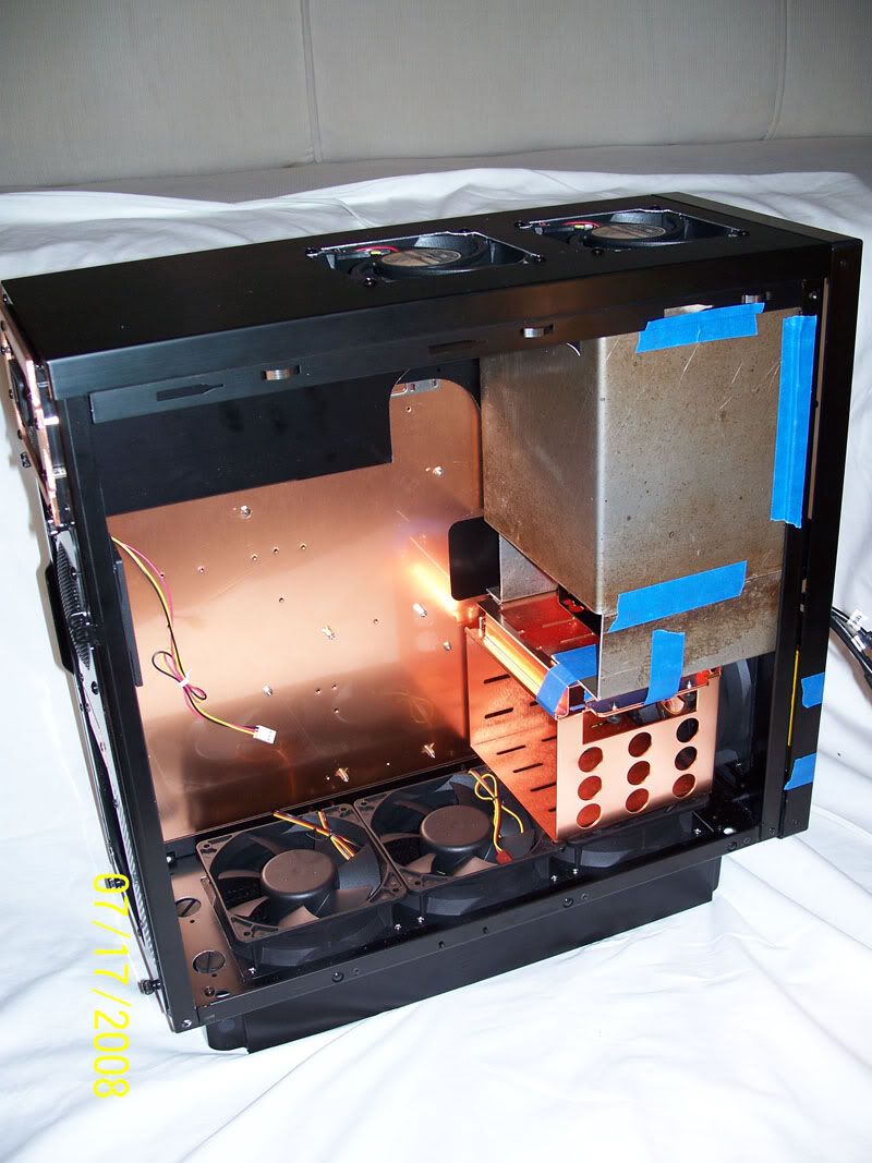
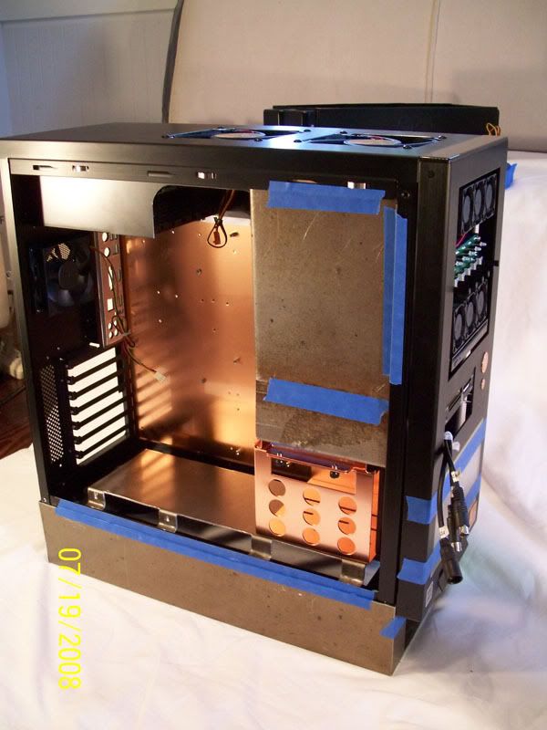
After a few hours with the dremel and jigsaw... then many more with a set of hand files I turned my lian-li case into the below:
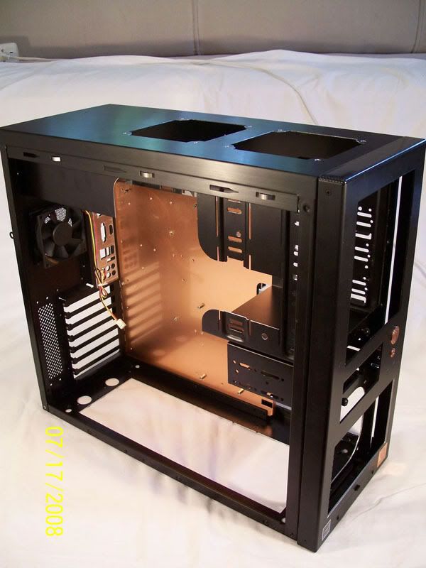
 ![]() The details: 
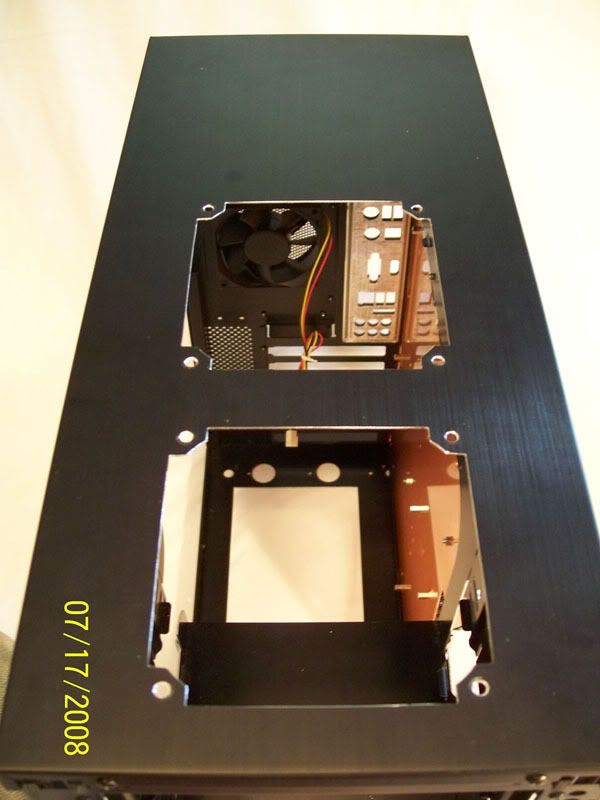
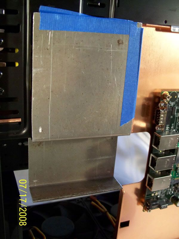
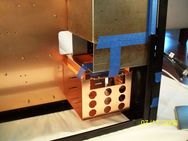
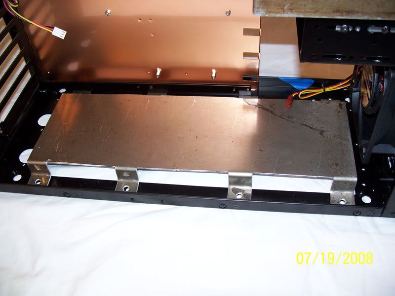
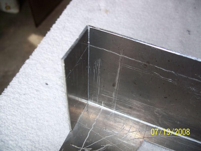
First I cut out some material from the drive bay area ![]() 
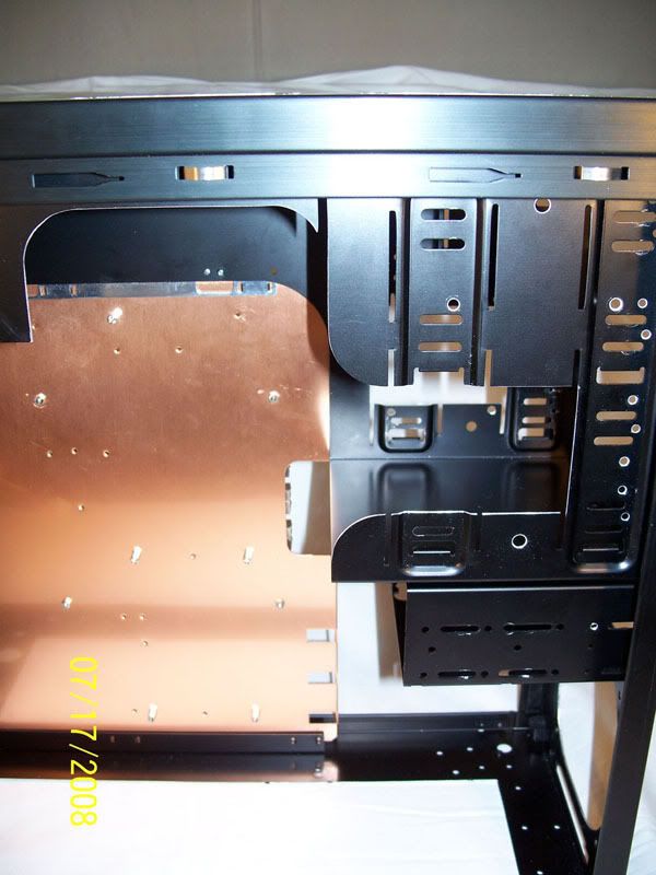
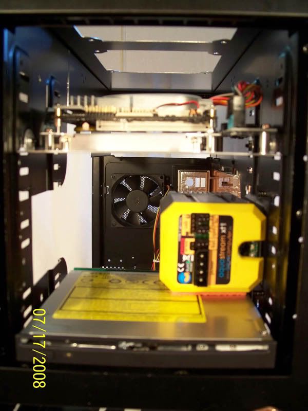
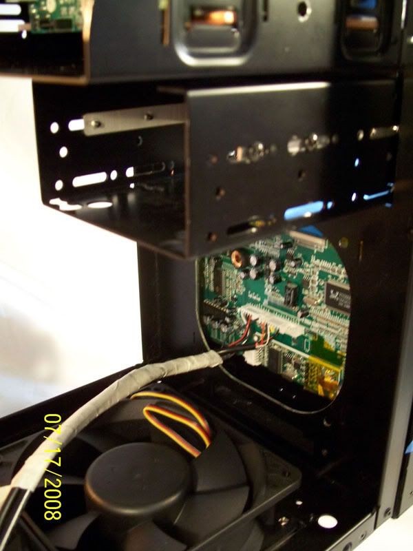
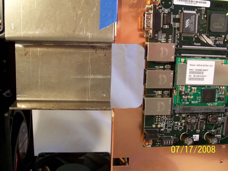
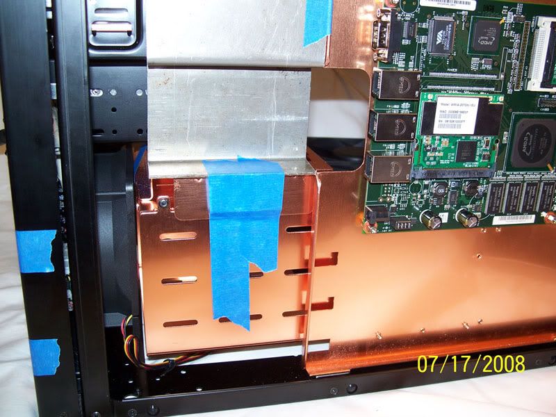
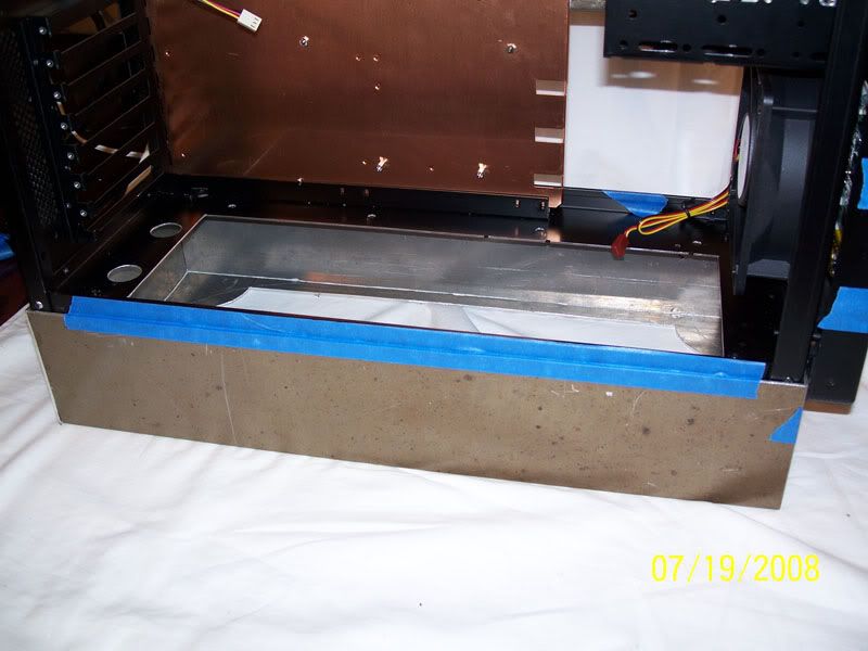
I then mounted the Alix 2c1 embedded linux firewall after installing the mini-PCI wifi-n card and the 1GB compact flash ![]() 
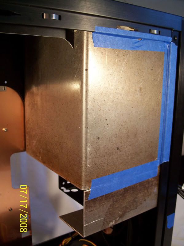
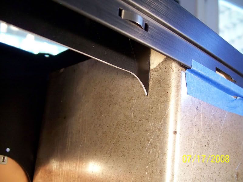
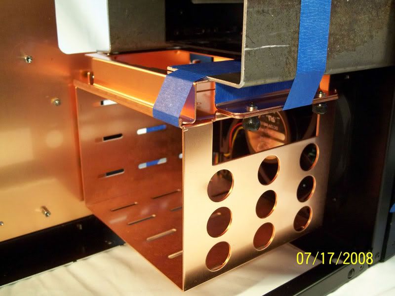
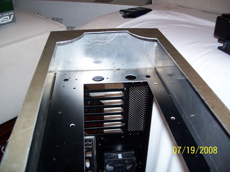
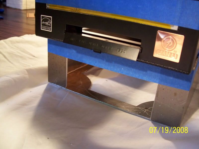
A cutout was made to allow space for the lan ports on the motherboard tray. Also a box was cut from the drive bay to allow for the pump to be mounted. ![]() 
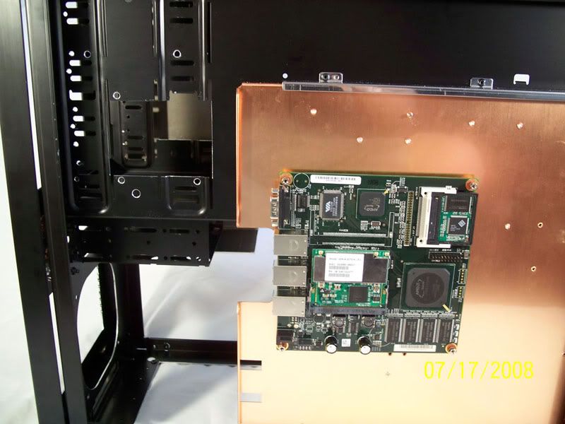
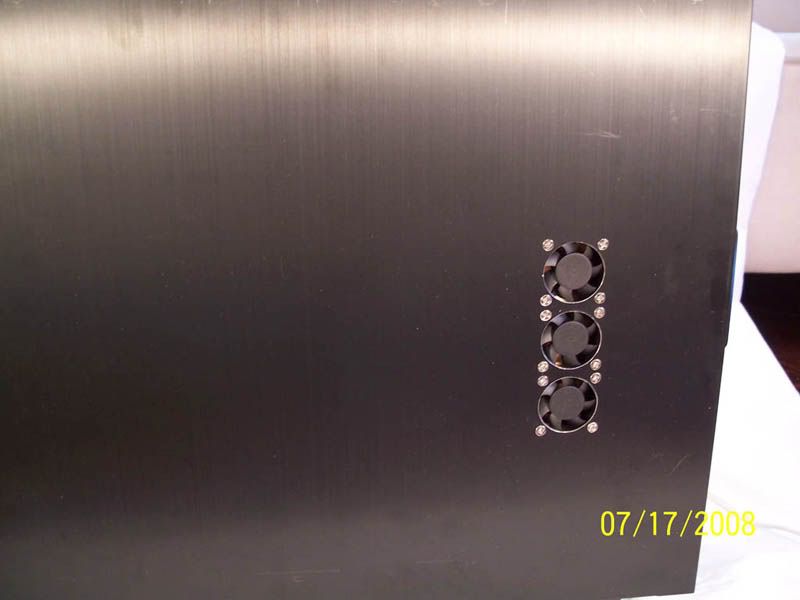
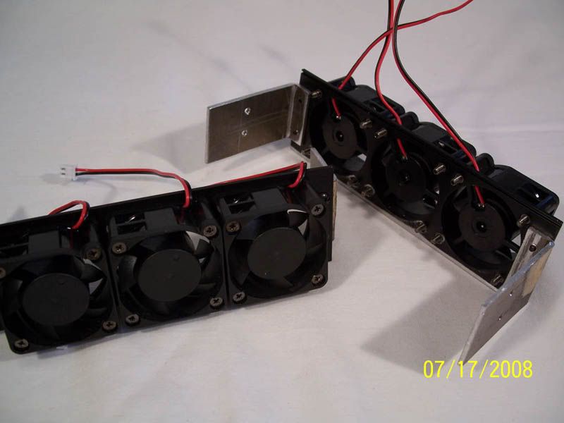
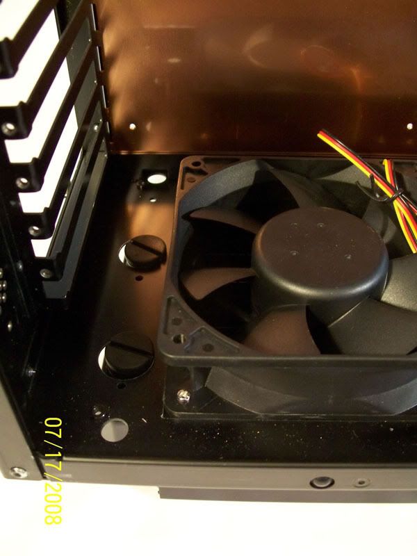
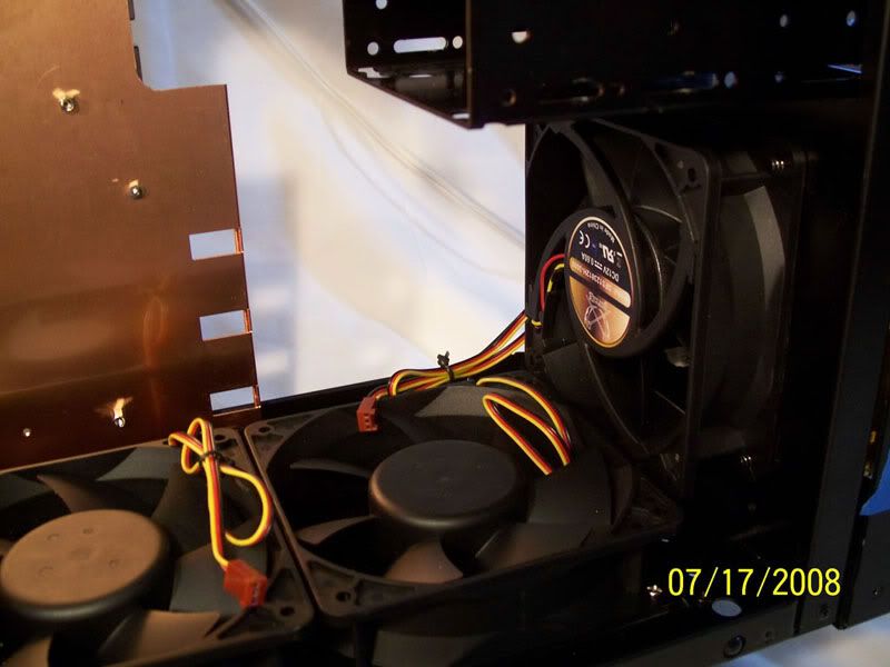
I haven't yet built the pieces that will guide the airflow; but i have installed the fans that will cool the Alix board. ![]() 
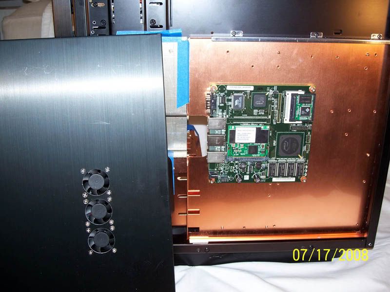
1/4inch slots will be milled on the panel and dividers will be constructed to guide the air out the slots. Until then, this is how it stands.
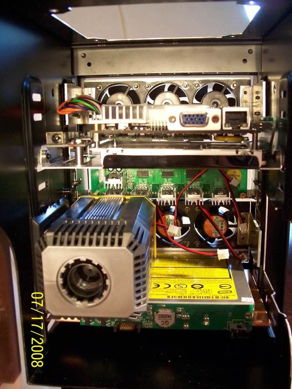
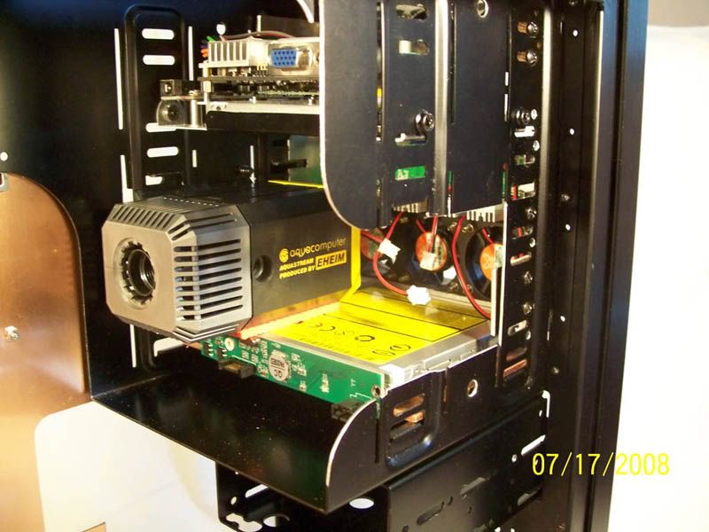
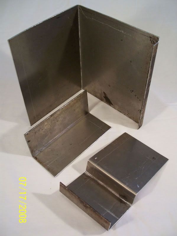
 ![]() Here is the Pump ![]() ![]() 
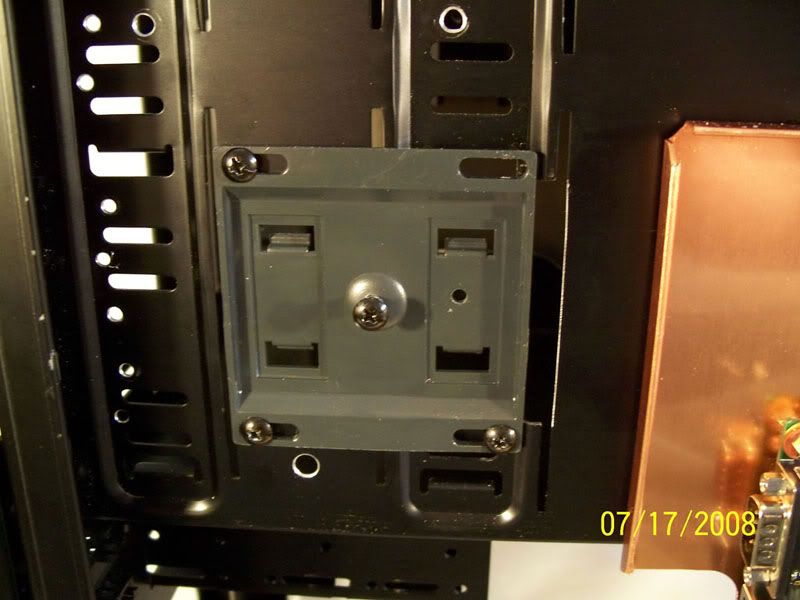
And the mounting bracket put into place ![]() 
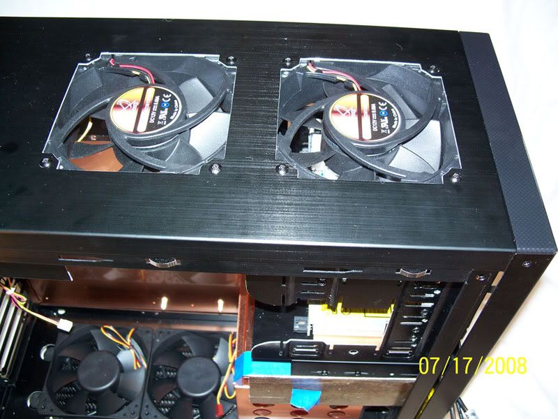
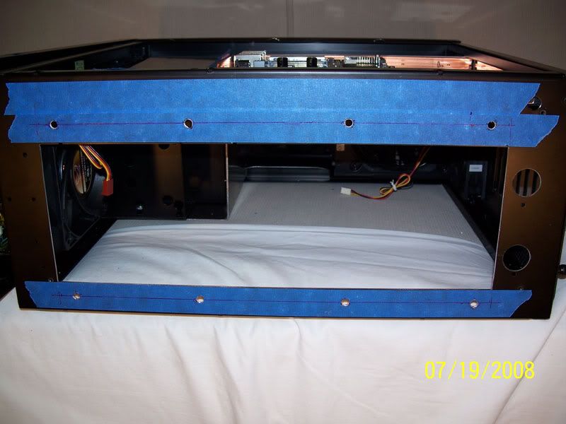
Two 120mm fan holes were cut from the top of the case ![]() ![]() 
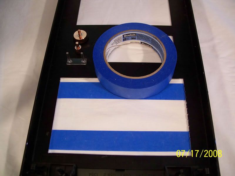
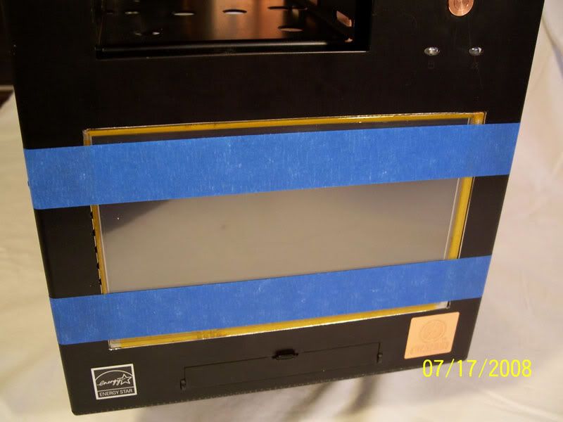
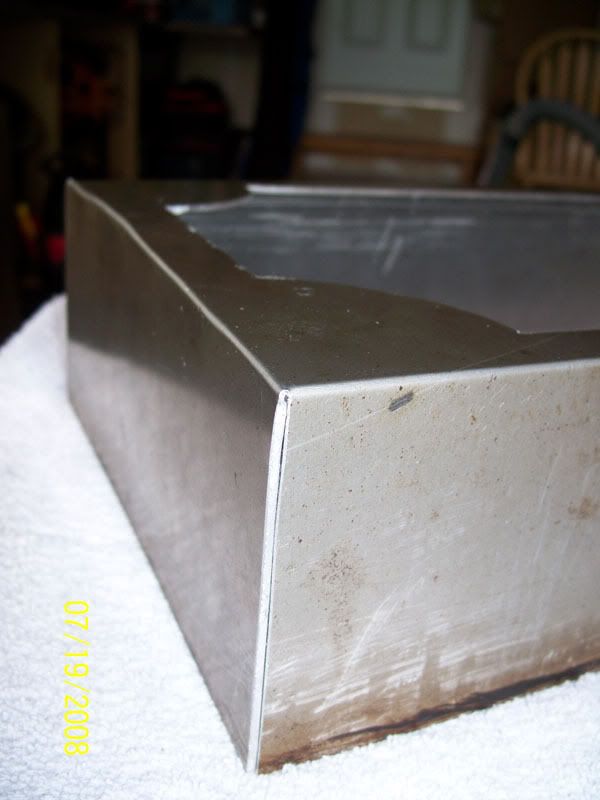
A large rectangle was removed from the front panel to make space for the 7" touch panel LCD ![]() ![]() ![]() ![]() ![]() ![]() 
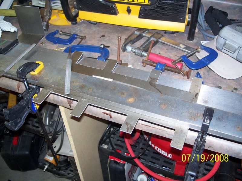
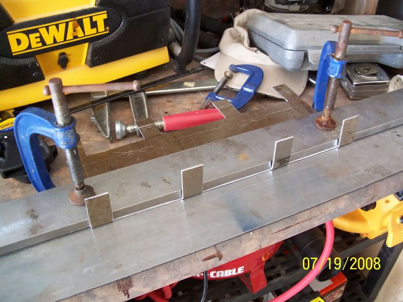
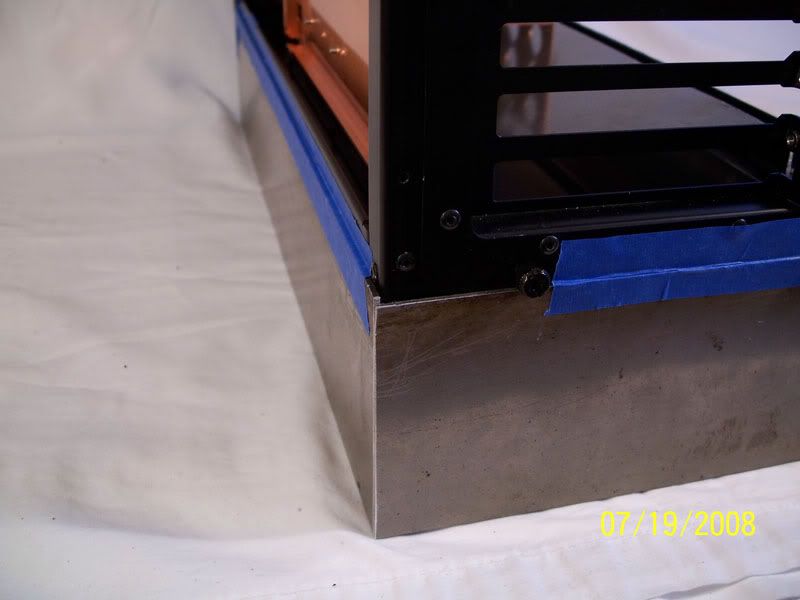
I then built another temporary bracket to hold the PSU in place. This too will be replaced with a CNC machined bracket. ![]() ![]() ![]() ![]() 
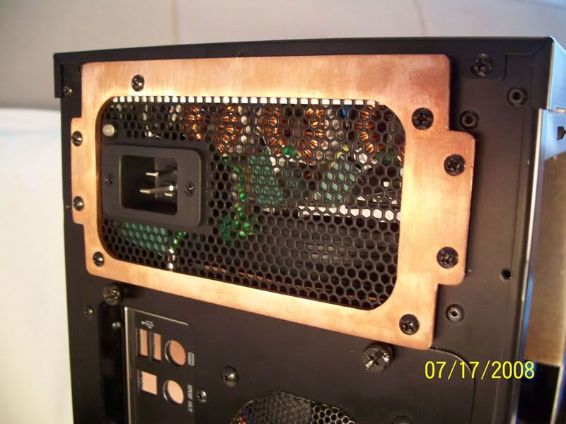
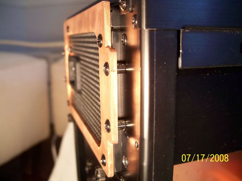
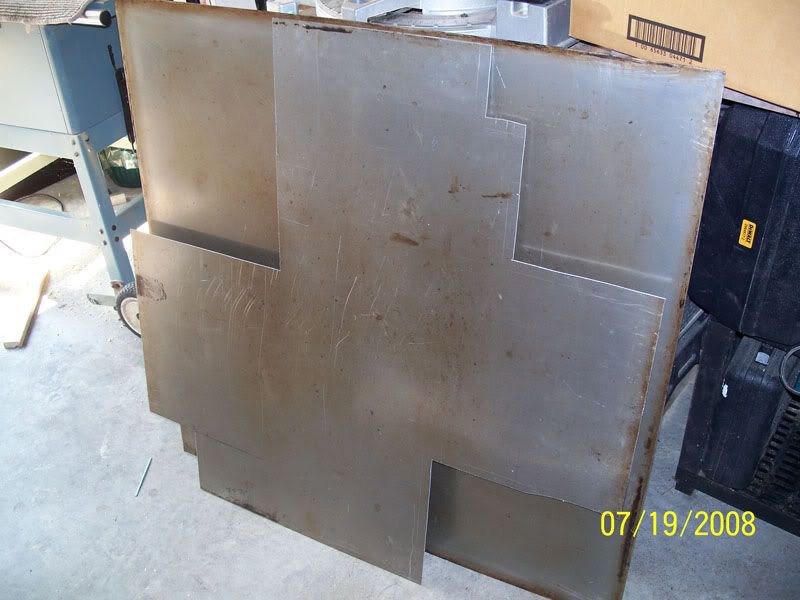
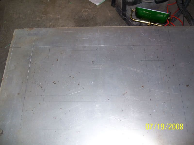
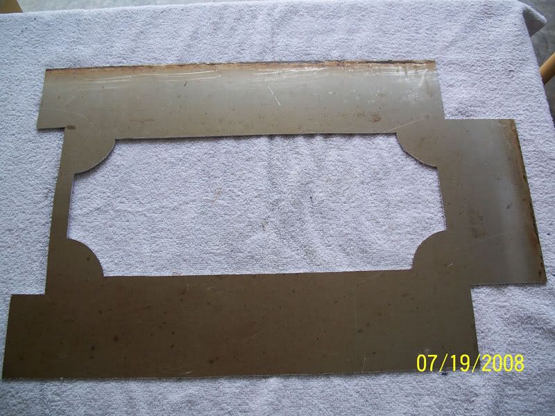
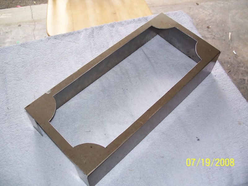
After cutting a piece of copper plate that will 'compression' fit into place. I used double sided foam tape to afix the slot load dvd-rw. ![]() 
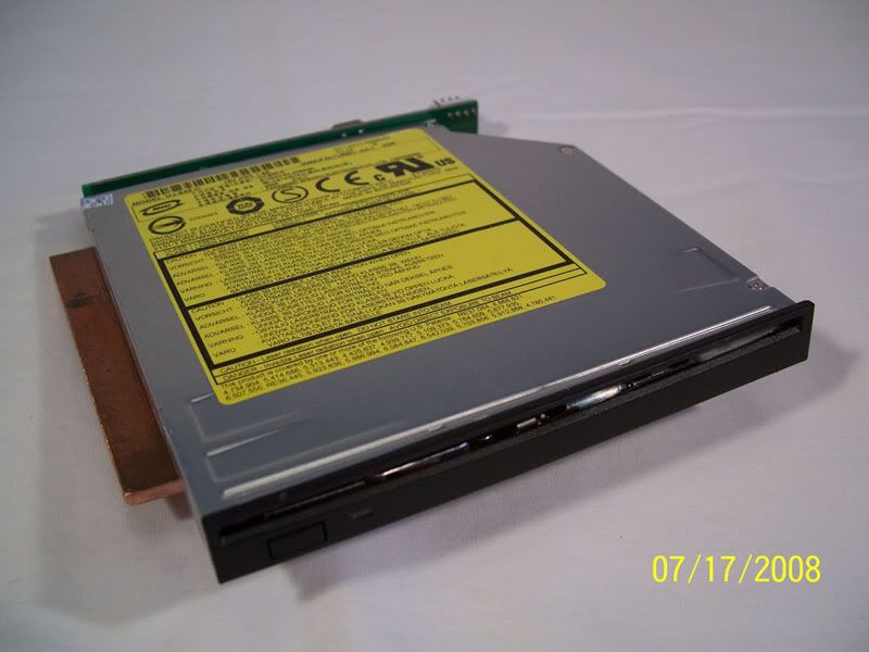
I then installed the slim-DVD to SATA adapter. ![]() 
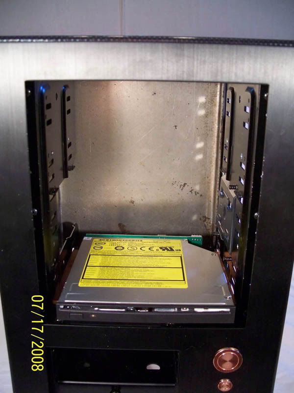
The drive is then squished into place, and holds suprisingly well ![]() Then the pump is mounted to the bracket, this foam is also temporary and will be replaced with black neoprene ![]() 
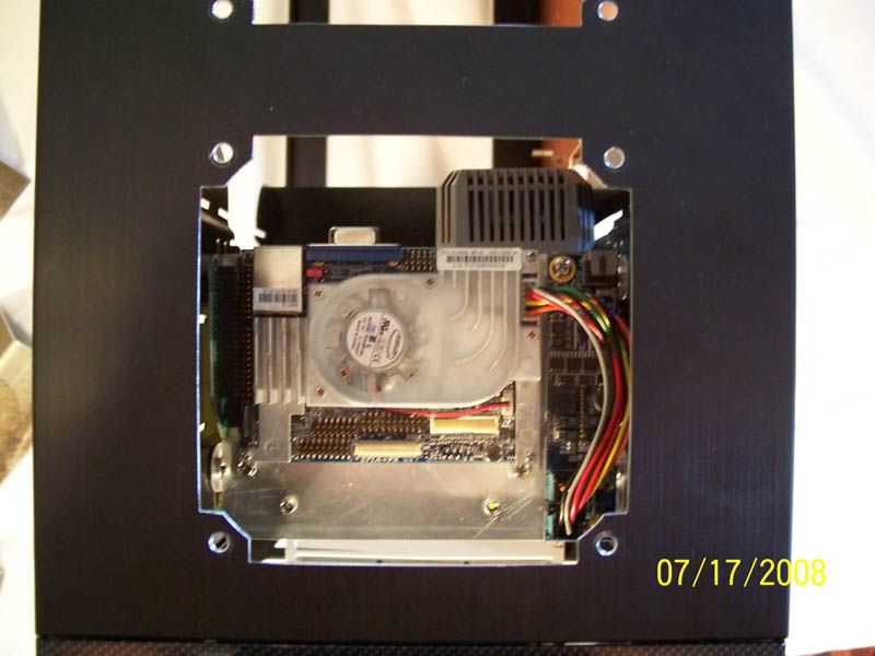
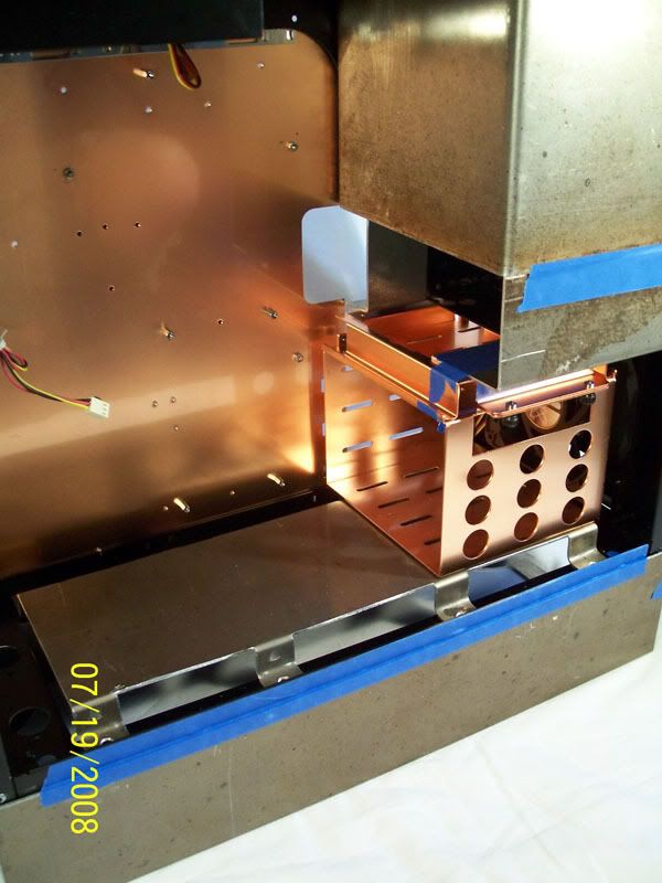
We then come to the Pico-ITX unit that will live in the drive bay ![]() ![]() 
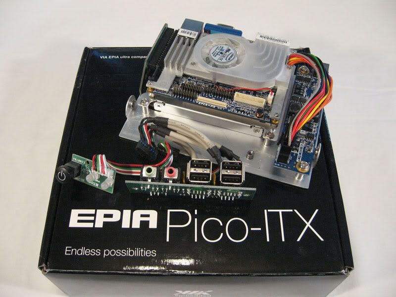
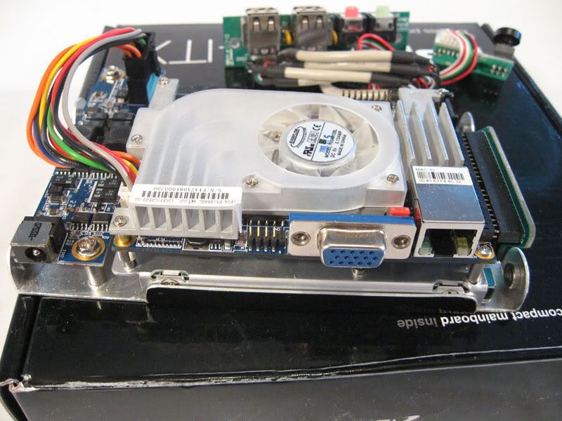
Here is is installed ![]() ![]() 
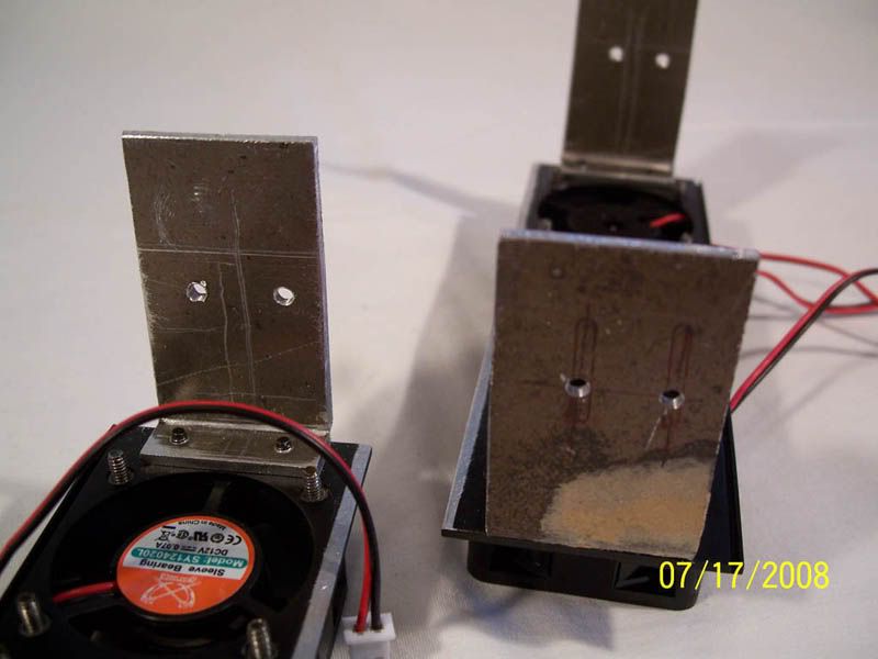
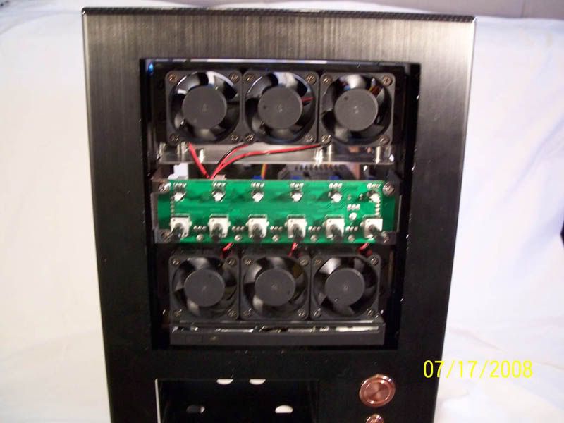
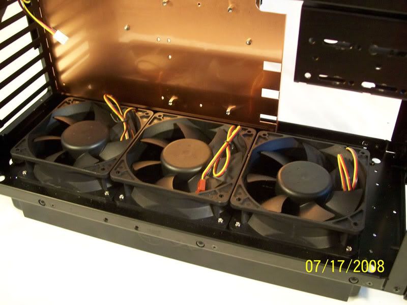
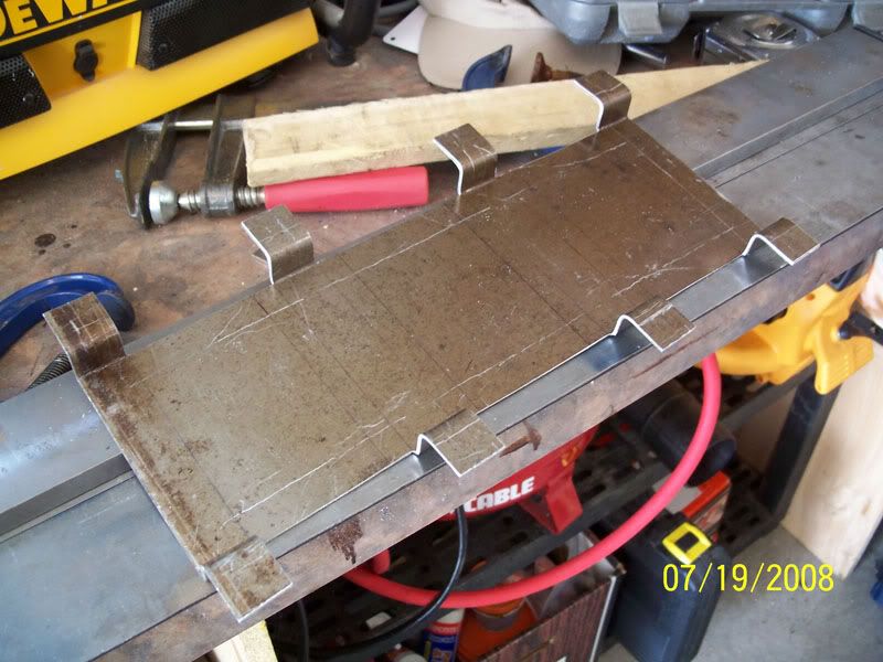
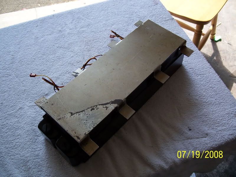
I then cut apart the Corsair Dominator fan assembly and made some temporary mounting brackets, the final brackets will be CNCd as well. ![]() ![]() ![]() 
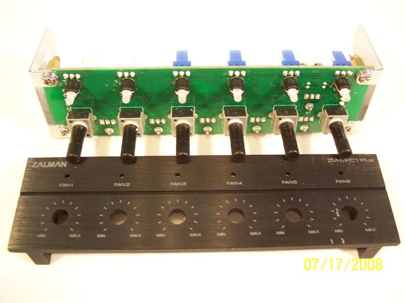
The zalman fan controller that I'll be using ![]() 
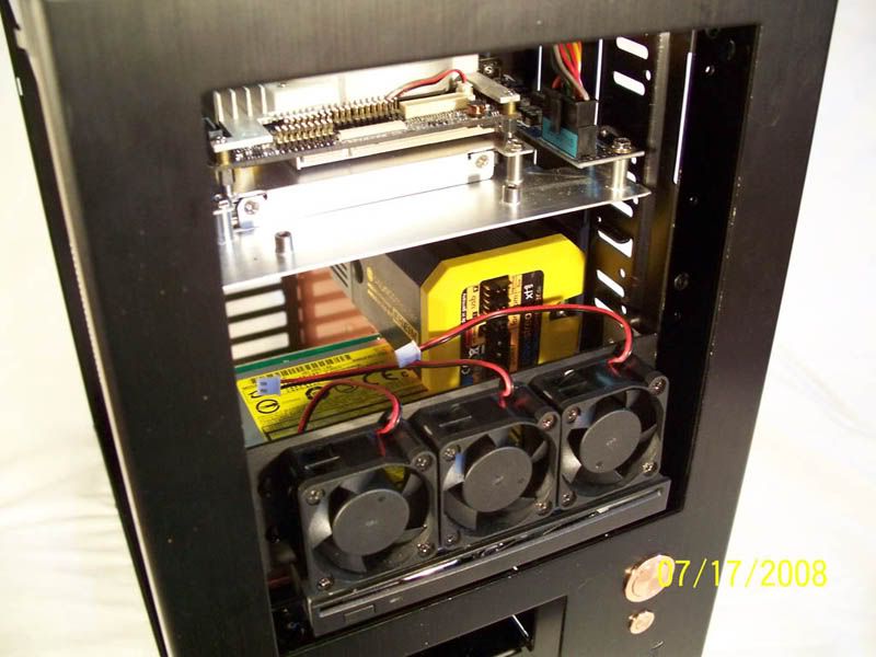
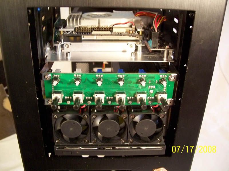
Here is the fan contoller installed ![]() 
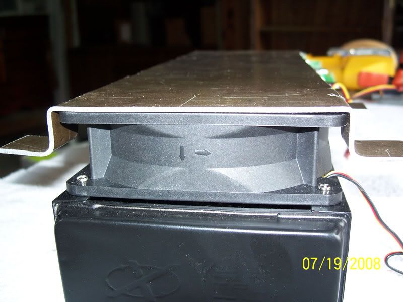
The final fan assembly and some glamour shots ![]() ![]() ![]() 
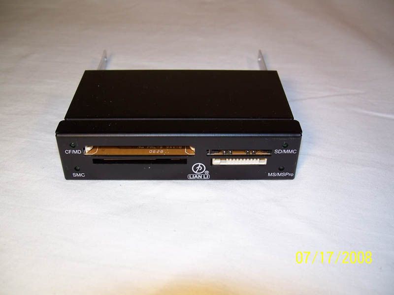
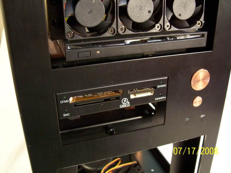
I also got a Lian-Li card reader, it will be stripped of its case by the end of this mod ![]() ![]() Last edited by Langer; 10-09-2008 at 08:47 AM..
|
|
#2
|
|||
|
|||
|
Here is the radiator I'll be using:
![]() ![]() The cutout I made, where it will live. I still have to make mounting brackets for it. ![]() ![]() ![]() ![]() This is where the hard drive bay will mount ![]() ![]() But first these need to be installed. Again these are only temporary, for fitting purposes, the final peices will be made from copper plate and will be CNC machined. ![]() ![]() ![]() ![]() ![]() Now we can suspend the drive cage ![]() ![]() ![]() And finally we come to the below images. This is how Project PrometheusCU sits right now, waiting on delivery of some of my watercooling components. ![]() ![]() As it stands I'm at about 30% complete. Here's a list of to-do's: >>The CAD drawings for all the parts to be cut from copper plate are complete - meeting with machinist on Tuesday to discuss fine details and re-engineer what I've got. >>I've completed a number of "engineering diagrams" that will describe how to use/disassemble the case. I'm going to have these engraved into the case - to add that factory engineered look >>Make mounts and a grill for the 3 rad fans >>Fabricate the copper 'skirt' that will add 4" to the system height and elevate the rad off the ground >>Wait on delivery of a new AquaComputer parts as well as a few other watercooling components. >>Mill slots into sides of front panel to allow for air intake on front mounted 120mm case fan >>Mill slots into side panel to alloy for Alix air cooling exhaust.- >>Then it's just wiring, which in itself is going to be a massive undertaking. I've had some 18AWG ribbon wire custom manufactured for this case (which will leave me with about 1200feet of extra wire for future changes... lol). The wire will be carefully folded and guided around the case, the intent is not to hide the wire, but make it a part of the aesthetic >>Build controllers for and plan some kind of exotic LED light display from white LED >>Replace all mounting hardware with a combination of Brighton branded socket cap head machine screws and socket countersink head machine screws Hope you all enjoy the work... I've poured pretty much everything I have into this case - in terms of both skillsets and money. Please feel free to leave comments, crits, suggestions. Tune in soon for more!
|
|
#3
|
|||
|
|||
|
Let us begin.
I've finished the rad mount prototype. I started with a 40"x40"x1/8" sheet of used aluminum. This panel was once used in the fabrication of Carbon Fiber sheets - the aluminum panel are used to help form the carbon panel. The carbon is cooked in a heated press at ~40,000tonnes. After a short while, about 100 carbon panels, the aluminum develops imperfections and heat stains - It's then thrown away. My Dad runs the Carbon Fiber plant so over the years I have developed a rather large collection of these aluminum sheets. ![]() After a bit of rough cutting with the trusty jigsaw I did some light filing to clean the cuts. ![]() Then onto bending ![]() The final product, minus the holes. ![]() Once that was complete I checked the fit - luckily the "measure 5-times cut once" methodology continues to work for me. ![]() A side view, note also that the final bends will be much more precise. I plan on having 'V' shaped groves milled into the copper plate where bends are needed to ensure accuracy. ![]() Then I had to drill precise holes in the the chassis. ![]() From there I did a test fit. (Note that the final design will include slots for airflow, I'll post an illustration later today.) Almost perfect, I eyeballed the holes in the rad mount prototype and a couple were off slightly. No big loss though because the final product will be machined precisely. ![]() Thanks for reading! More to come.
|
|
#4
|
|||
|
|||
|
Another update for you guys, but there will be more to come this weekend.
I've finished the tray prototype that will both house the radiator, and lift Prometheus 3.5" off the ground. We again start with some aluminum plate. As you can see I've marked out the areas to be cut. ![]() Like the above post, I've put the jigsaw to work. ![]() After using the dremel to crudely score the bending lines I put the piece in my bending brake. This is what I came up with ![]() A close-up of the joints. ![]() ![]() Then a test. Perfect Fit! ![]() ![]() ![]() ![]() And here is how it sits right now. In fabricating these parts I've realized that the final design will need to seat the radiator about 1/4" lower. As you can see from the pics, I haven't left enough room for the front rad fan to breathe. But that's why I made these prototypes... to narrow in on design flaws such as that. ![]() ![]() That's all the fabricating I'll be doing today, tune in later I'll have some illustrations posted. Thanks for reading!
|
|
#5
|
|||
|
|||
|
A small update for the masses.
Here is an idea of what a couple of the copper components will look like. From left to right - Front Facade Panel, Top Exhaust Fan Grill, Radiator Grill/Mount. I'll post the designs for the rest of the pieced some time tomorrow; along with some of the illustrations that I'm going to have engraved throughout the case. black = cut grey = engrave dashed = bend *click for supersize* ![]() Added a a 'jagged edge' to the front facade. Since the touch panel LCD covers the traditional front air intake I will need to mill slots in the side of the front panel to act as air intake. The jagged edge will make space for these intake slots. The slots can be seen in the initial design concept illustration Thanks for reading! Tune in soon for more. As always, crits are welcome and appreciated.
|
|
#6
|
|||
|
|||
|
Small update
Black lines = cut Grey lines = engraved Dashed lines = bend Here is my concept for the plaque replacement on the back of the chassis ![]() I've also completed the concept for the drive bay enclosure (the piece seen taped into place in this image). I modified the original design to encase the lower 3.5" drive bays, and allow for a fill point (nearly forgot about that). *click for supersize* ![]()
|
|
#7
|
|||
|
|||
|
*slow clap*
*cries* It's just so beautiful.
|
|
#8
|
|||
|
|||
|
Damn, this mod is amazing.
*claps* as well. Keep up the good work! ![]()
|
|
#9
|
|||
|
|||
|
Incredible start.
I will be watching this for sure!
|
|
#10
|
|||
|
|||
|
Woah....
subbed
|
|
#11
|
|||
|
|||
|
Impressive.
|
|
#12
|
|||
|
|||
|
@Vzylexy - Tears even? didn't expect that. Thanks for the kind words
@Kuyt - Thanks, I'll do my best @ivandurago -Thanks, tune in soon! @aVaLaNcHe - Thanks! @bigddybn - Thanks! With any luck the 2nd of 3 deliveries of my water cooling parts should be here tomorrow. Also tomorrow I have plans on heading over to my Dad's Carbon Fiber manufacturing plant to speak with the machinist there, and hopefully make some test cuts on the CNC router. I know I'm excited. QUESTION for the water cooling experts out there. I have 5 case fans + 1 PSU fan venting outwards and only 1 fan pushing inwards; I fear this may be a problem. I'm worried about creating a really low pressure zone inside the case, and putting strain on the poor front air intake (120mm, 133cfm). Not that all the fans will be running full boar 24/7 and the fan speeds could be adjusted to avoid this situation. Is there any reason why I can't 'suck' air through the rad into the case? Instead of pushing air out of the case through the rad. To me this makes more sense seeing as the air temps outside should be, considerably, cooler. If this isn't recommended then the plan is to redesign the lower part of the side panel to channel air into the rad from outside the case. Thanks for reading! Last edited by Langer; 07-21-2008 at 09:11 AM..
|
|
#13
|
|||
|
|||
|
ok that anime snip just ruined the thread..
|
|
#14
|
|||
|
|||
|
LOL.
For some reason though the Daft Punk - Technologic song is just playing in my head........ -_-;; ANYWAY: On topic: Where do you plan to get the engraving done? Yourself? Store? Internet?
|
|
#15
|
|||
|
|||
|
6 fans out and one fan in will turn your case into a vacuum cleaner. Dust bunny breeding will be its specialty.
I wouldn't be keen on seeing the rad fan reversed - why pull warmed air inside? Why not reverse the two top fans? Get a top-bottom flow, though the PSU will be running counter to that. You could invert the PSU and have it not contribute to case venting - with the PSU fan on top, it will only cool itself. Don't worry about top-bottom being counter to the gravity-induced hot air flow - that will be very small effect compared to the forced air flow. With the PSU out of the picture, you'll then have 3 out and 3 in. You could then modify the fan speed to create a slight positive pressure and keep dust out. Of course, you'll need good filters on the intake fans.
|
|
#16
|
|||
|
|||
|
There isn't much of a problem with switching the direction of the radiator fans. Sure you will be pumping the hot air inside of the case, but most of the components you care about anyways are being watercooled so it wont matter. Everything else will hardly be effected by slightly higher case temperatures.
|
|
#17
|
|||
|
|||
|
Awesome! Keep the updates coming.
|
|
#18
|
|||
|
|||
|
@AthlonXP - I'm prone to agree, but the intent was in support - that's the important part.
@Ang - It just so happens that the CNC router that I'll be using comes with a large supply of bits, one of which is an engraving head. Failing that I've already planned for a backup - I befriended a local Jeweler who has an engraver... and an immense amount of skill. @Michael Daly - Thanks for the advice, I'll certainly take it into consideration when it comes time for final assembly. @Erasmus354 - That's exactly the was I saw it, we'll see how everything works out when I do temp testing. @Shambler - Thanks mate! Thanks again guys! See you soon, with progress!
|
|
#19
|
|||
|
|||
|
Nice clean cuts.
|
|
#20
|
|||
|
|||
|
Here is the accumulation of all the final part concepts that I'm going to be milling from Copper plate.
(as always, click for supersize) 1: Drive Bay Enclosure - Left Side ![]() 2: Drive Bay Enclosure - Right Side ![]() 3: Authenticity Plaque ![]() 4: Front Facade ![]() 5: Bottom Tray/Radiator Housing ![]() 6: Parts List Plaque ![]() 7: Radiator Fan Grill/Mount ![]() 8: Top Fan Grill ![]() 9: Front Lower Tray/LCD housing ![]() Enjoy! Last edited by Langer; 07-22-2008 at 08:09 AM..
|
![]() |
| Thread Tools | Search this Thread |
|
|